Dual-band (28/38 GHz) Yagi–Uda Antenna with Corrugated Radiator and Triangular Reflectors for 5G Mobile Phones
Asmaa E. Farahat and Khalid F. A. Hussein
Microwave Engineering Department
Electronics Research Institute, Cairo, 11843, Egypt
e_asma_e@yahoo.com, Khalid_elgabaly@yahoo.com
Submitted On: February 27, 2020; Accepted On: July 6, 2021
Abstract
A novel printed design of a Yagi–Uda antenna is introduced for dual-band operation at 28/38 GHz. A corrugated strip dipole with a capacitively end-coupled extension strip is employed as the driven element. The proposed antenna has two triangular-shaped reflectors and one director. The driven dipole is fed through a coaxial feed line constructed as three unequal length transition strips. A four-port MIMO antenna system constructed using the proposed Yagi–Uda is suggested for mobile phones. CST simulator is used to study the effect of the different design parameters on the antenna gain and the operating bands. Numerical and experimental investigations are achieved to assess the performance of both the single-element antenna and the four-port MIMO antenna system. It is shown that the simulation results agree with the experimental measurements and both show good performance of the single antenna as well as the MIMO antenna system. The bandwidths achieved around 28 GHz and 38 GHz are about 4 GHz and 1.4 GHz, respectively. The gain of the antenna is about 9 and 10 dB at 28 and 38 GHz, respectively. The four-antenna configuration shows radiation pattern diversity required for MIMO system. The envelope correlation coefficient (ECC) and the diversity gain (DG) are calculated and the results show that the proposed MIMO antenna system is suitable for the forthcoming 5G mobile communications.
Index Terms: MIMO, Yagi–Uda, spatial diversity.
I. INTRODUCTION
It has been recently reported that mm-wave in the 28 GHz and 38 GHz frequency bands can be used in wireless cellular communication systems [1]. The future fifth generation (5G) applications require higher bandwidths for higher data rates provided by the millimeter wave bands [2]. However, as the operating frequency increases, the wavelength of the signal becomes shorter and consequently the free-space path loss is higher, according to Friis transmission equation [3], [4]. Thus, high-gain antennas may be needed to compensate for the large free-space path losses and various forms of fading that can be observed in the communication channel [5], [6]. MIMO antenna system can offer advantages when considering multipath effects. The combination of both high gain and MIMO configurations can provide some novel antenna and circuit solutions for mobile communication applications at mm-wave frequencies. This can minimize the operating costs of any supporting power amplifiers and other control circuitry [7].
The frequency spectrum around 28 GHz, 38 GHz, 60 GHz, and 73 GHz are estimated bands under consideration for 5G technology. These millimeter wave bands would bring new challenges in the implementation of MIMO antennas for handheld devices [8]. With the fast development of the industry of wireless communication, there is an increase in the demand of multiband and highly isolated MIMO antennas for terminal users of cellular networks. Various dual-band MIMO antennas have been reported in literature. In [8], a 44 28/38 dual-band MIMO antenna system employing a round patch EBG Cell is introduced with low mutual coupling at both bands even at a close distance of 0.7 mm. In [9], a linear array of dual band 28/38 GHz Yagi–Uda antennas for 5G mobile MIMO systems is introduced. In [10], a dual-band MIMO antenna system composed of two orthogonal elements operating in the frequency bands 1.62–3.2 GHz and 4.4–5.9 GHz. In [11], a 28/38 dual-band slotted rectangular patch antenna with proximity coupled feed was built on a multilayer substrate of low-temperature co-fiber ceramics. The antenna achieves wide bandwidth of more than 4 GHz at both operating frequencies. In [12], a dual-band 28/45 circular microstrip patch antenna with an elliptical slot is presented with bandwidths of 1.3 GHz and 1 GHz at 28 GHz and 45 GHz, respectively. A circular radiating patch placed non-concentrically inside a circular slot etched off the ground plane is presented in [13], operating at 28 and 38 GHz bands.
Yagi–Uda antennas are good candidates for millimeter wave and microwave applications due to their high gain, high efficiency, low-cost, and ease of fabrication. They are one of the most known endfire radiation pattern antennas that can achieve medium gain. In [14], a Yagi–Uda antenna operating at 24 GHz has been implemented in an 11-beam system using a planar array and a two-inch Teflon spherical lens. The use of Yagi–Uda for mm-wave applications has also been demonstrated in [15], where a corrugated ground plane is employed as a reflector to improve the gain for a linear antenna array operating at 60 GHz. A substrate-integrated waveguide Yagi–Uda antenna having the advantages of low profile and light weight was reported in [16]. A dual-band printed Yagi–Uda with enhanced reflectors to increase the gain is introduced in [17]. In [18], a modified Rotman lens feeding an antipodal Yagi–Uda antenna array is designed and fabricated for 5G wireless communications at the 28 GHz band. Other types of high-gain antennas are investigated in literature for mm-wave MIMO application. For example, the antenna proposed in [19] consisting of a substrate integrated waveguide (SIW) slot and two SIW grooves operating in the Ka-band with a gain of 9.5–11 dBi and good isolation in the frequency range 26.8–28.4 GHz, but this antenna occupies large space (39.8 mm × 33.4 mm) on the board.
This paper presents a compact printed dual-band Yagi–Uda MIMO antenna system for 5G mobile communication. The modified Yagi–Uda proposed design in this work can be very attractive for next generation wireless terminals due to its high gain, good wideband performance, and small form factor. Practically, the proposed MIMO antenna system can be integrated on the far top or bottom side corners of a mobile phone backplane, or positioned at the edges of the mobile chassis. The detailed literature review described above shows that the simple MIMO antenna design, as proposed in this paper, has not been investigated previously offering good integration, compact size, high gain, and simple fabrication for 5G mm-wave mobile handset applications.
II. THE PROPOSED DUAL-BAND YAGI–UDA ANTENNA
A. Design of the driven dipole, reflectors, and director
The present section describes the design of the proposed Yagi–Uda antenna. The antenna is fed through a microstrip line. A microstrip line to CPS line transition is employed. The length of a resonant free-standing dipole can be approximated,
| (1) |
where, is the free-standing dipole length, and is the free space wavelength. A dipole printed on a substrate’s Rogers RO3003 with epsilon requires the dipole length to be modified as,
| (2) |
To get the printed dipole with dual resonant frequencies at 28 and 3 GHz, the value of in (1) is set to the free space wavelength corresponding to 38 GHz and then an extension strip is capacitively end-coupled to each of the dipole arms through an infinitesimal gap. The length of the strip and the gap are set so that the extended dipole structure has two resonances at 28 and 38 GHz. Each dipole arm has three equally spaced corrugations with dimensions set for good impedance matching. Two reflectors and one director are employed to enhance the antenna gain. The preliminary dimension of the director is 5% shorter than the driven dipole, while each reflector is 5% longer than the driven dipole. The accurate length of the director and the reflectors are set with the aid of electromagnetic simulation using the CST simulator.
B. Design of the feeding balun
The feeding balun is composed of four stages. The first three stages are cascaded microstrip line regions with different lengths and widths designed for impedance matching. The fourth stage is parallel strip (twins) transmission line. One of the dipole arms and its extension strip are printed on the bottom layer of the substrate and connected to the ground plane. The geometry with indicated symbolic dimensional parameters of the proposed antenna is shown in Figure 1. The dotted red line denotes the borders of the printed regions on the back side of the substrate.

Fig. 1. Schematic of the proposed design for the Yagi–Uda antenna.
III. MIMO ANTENNA SYSTEM FOR MOBILE 5G PHONES
A MIMO antenna system is constructed using four elements of the proposed dual-band Yagi–Uda antennas operating in the 28/38 GHz bands for the forthcoming 5G mobile phones. The four antennas are suggested to be placed on the edges of a mobile phone as shown in Figure 2. The separations between the four antennas lead to the spatial diversity required for the target 5G applications allowing high performance at high bit rates. The performance of the MIMO antenna system including the return loss at each antenna port and the coupling coefficients between the different ports is investigated. The radiation patterns produced when each port is excited alone are shown to be suitable for the pattern diversity scheme.
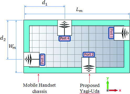
Fig. 2. The four-port MIMO antenna system proposed for 5G mobile phones.
IV. RESULTS AND DISCUSSIONS
In this section, both the numerical results obtained by electromagnetic simulations and the experimental results obtained by microwave measurements for the fabricated prototypes of the single antenna and the MIMO antenna system are presented, discussed and compared. The presented results are concerned with investigating the return loss and radiation patterns of the single CPS- and MS-fed Yagi–Uda antenna. Also, the results are concerned with the coupling coefficients, the radiation patterns, and the diversity gain (and the corresponding envelope correlation coefficient) of the four-port MIMO antenna configuration.
A. Performance assessment of the proposed dual-band antenna
A.1 Return loss and bandwidth
The proposed Yagi–Uda antenna is designed on Rogers RO3003C with dielectric constant , dielectric loss tangent and height . The metal strips and ground are made of copper with conductivity and thickness t = 0.032 mm. The design parameters are listed in Table 1. The antenna is placed in the -plane with the feed line aligned with the -axis. The dependency of the reflection coefficient, , on the frequency over a wide band for the proposed dual-band Yagi–Uda antenna is presented in Figure 3. It is clear that the impedance is perfectly matched at the two frequencies and . At , the band width is about , whereas at 38 GHz, the band width is about and can operate with matched impedance over the frequency range . The radiation efficiencies are at 28 GHz and at 38 GHz.
Table 1: Dimensional parameters for the proposed Yagi–Uda antenna
| Name | Value (mm) | Name | Value (mm) |
| 2.4 | 0.5 | ||
| 3.62 | 4.02 | ||
| 1.0 | 1.95 | ||
| 3.4 | 2.79 | ||
| 0.62 | 0.35 | ||
| 2.5 | 1.0 | ||
| 6.72 | 7.6 | ||
| 0.8 | 0.2 |
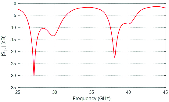
Fig. 3. The frequency responses of the reflection coefficients of the proposed CPS-fed and MS-fed Yagi–Uda antennas with the dimensional parameters listed in Table 1.
A.2. Radiation patterns
The normalized radiation patterns for the proposed dual-band Yagi–Uda antenna at 28 GHz and 38 GHz in the planes and are presented in Figures 4 (a) and 4 (b), respectively. The maximum gain is 8.84 dBi at 28 GHz and 9.97 dBi at 38 GHz. Such radiation patterns are proper for MIMO antenna system composed of multiple units of such dual-band radiating elements for pattern diversity schemes.
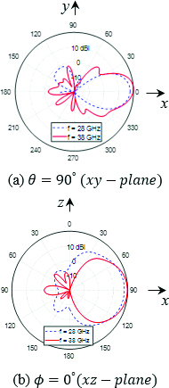
Fig. 4. Gain patterns of the proposed dual-band antenna at 28 and 38 GHz in the and .
B. Parametric study for optimum design of the proposed antenna
The CST simulator is used to study the effects of the geometric parameters of the proposed antenna presented in Figure 1 on the antenna performance. The purpose of the parametric study is to arrive at the optimum design that gives good values of the reflection coefficient () such that and to maximize the gain at the required operating frequencies 28/38 GHz.
B.1. Parametric study for optimum return loss
The most effective parameter that controls the input impedance of the proposed Yagi–Uda and, hence, the operating resonance frequencies is the dipole length . The effect of on the operating frequencies and bandwidth is illustrated in Figure 5. As shown in Figure 5, this parameter has significant effects on the resonant frequency as well as the value of at these resonances. It should be noted that the other dimensional parameters have the values given in Table 1. The value of gives the best matching bandwidth at the required 28/38 GHz operating frequencies. The bandwidth at 28 and 38 GHz is about 4 and 1.5 GHz, respectively.
Another parameter that affects the value of the reflection coefficient at the resonance frequencies is the length of the extension strip . This extension strip is capacitively coupled to the dipole and acts as a capacitive impedance which improves the impedance matching at the operating frequencies. The dependence of the reflection coefficient on frequency for different lengths of the extension strip is presented in Figure 6.
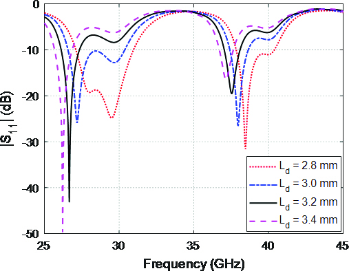
Fig. 5. Dependence of on the frequency for different values of the geometrical parameter .

Fig. 6. Dependence of on the frequency for different values of the geometrical parameter .
B.2. Parametric study for optimum gain
The most important parameters which affect the gain of the antenna at the operating bands are the length of the first and second reflectors, respectively, and their locations. Another parameter which controls the value of the gain is the length of the director and its location. The dependence of the value of the gain in the forward direction () on the location of the first reflector for different values of the reflector length is presented in Figure 5. The other design parameters are set according to the values in Table 1. The effect of the second reflector length and location on the gain is shown in Figure 6. The rest of the design parameters are as shown in Table 1.
The director length and where it is placed behind the antenna effect on the gain is studied for different director lengths and locations and presented in Figure 7. It is clear from Figures 5, 6, and 7, that there is an optimum location for placing each of the reflectors and the director to obtain the highest gain.
It is clear from the Figures 5 and 6 that the gain is almost linearly varying with the reflector length for the 38 GHz and has a peak at specific location for the 28 GHz. In Figure 7, the value of the gain by varying the director location is almost constant at 28 GHz, and has a peak value at certain location at 38 GHz.
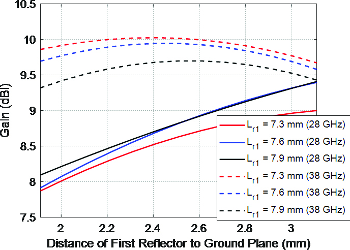
Fig. 7. Effect of the first reflector length and location on the gain at the two operating frequencies 28/38 GHz.
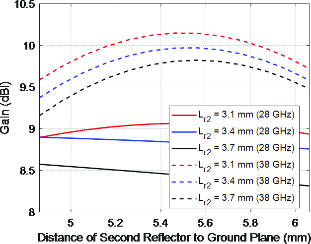
Fig. 8. Effect of the second reflector length and location on the value of the gain at both operating bands.
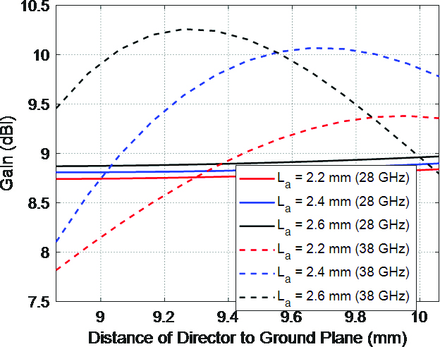
Fig. 9. Effect of the director length and location on the gain at the two operating frequencies 28/38 GHz.
C. Performance assessment of the proposed four-port MIMO antenna system
C.1. Impedance matching and coupling coefficients
A four-port MIMO antenna configuration mounted on a mobile phone chassis with dimensions and , and separation distances between the antennas and as that shown in Figure 3 is studied. Each antenna is printed on a 0.25 mm Rogers RO3003 substrate with the dimensional parameters listed in Table 1. Figure 10 shows the dependence of the self and mutual scattering parameters on the frequency over a very wide band. It is shown that the reflection coefficients at the different antenna ports are almost identical and satisfy the impedance matching condition (low return loss ) over the lower and upper operational frequency bands which are centered at and , respectively. On the other hand, the mutual scattering parameters show very weak coupling between the antenna ports, where all these coefficients are maintained below over the entire frequency range.
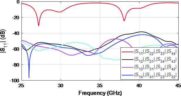
Fig. 10. Simulated frequency response of the reflection and transmission coefficient of the four-port Yagi–Uda MIMO antenna system.
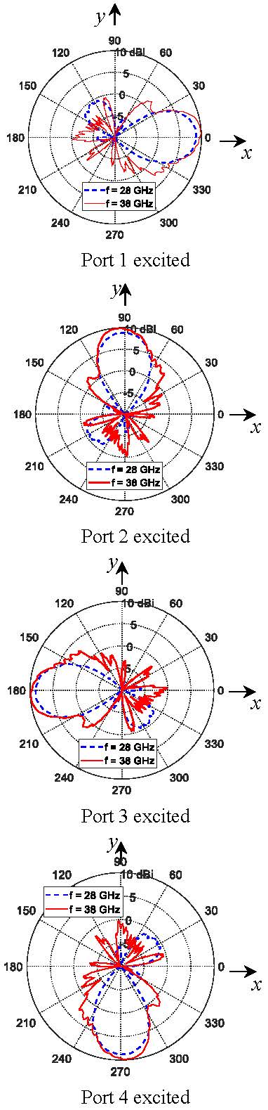
Fig. 11. Radiation patterns in the antenna plane for the four-port MIMO antenna using the proposed dual-band antenna at 28 and 38 GHz.
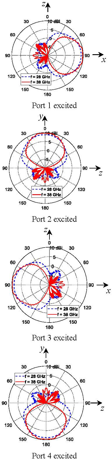
Fig. 12. Radiation patterns in the plane normal to the antenna plane for the four-port MIMO antenna using the proposed dual-band antenna at 28 and 38 GHz.
C.2. Radiation patterns of the MIMO antenna system
The radiation patterns produced by the proposed MIMO antenna system when exciting each port alone are presented in Figures 11 and 12 at 28 and 38 GHz, where the radiation patterns are shown to satisfy the diversity required for the mobile phone MIMO systems. The maximum achieved gain at 28 GHz is about 8.9 dBi for both antenna 1 and antenna 3, and 9.05 dBi for antenna 2 and antenna 4. Whereas, the maximum gain at 38 GHz is about 9.78 dBi for both antenna 1 and antenna 3, and 9.89 dBi for antenna 2 and antenna 4. Besides the reasonable size of the MIMO antenna system and the fairly wide separations between the antennas that produce high-diversity gain, the obtained pattern diversity provides excellent solution for the forthcoming 5G mobile communication systems.
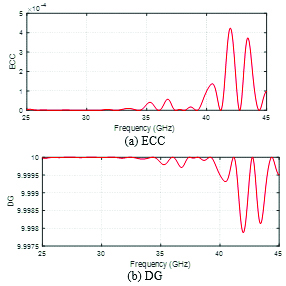
Fig. 13. Frequency dependence of the ECC and DG of the four-port MIMO antenna proposed in the present work.
C.3. Envelope correlation coefficient and diversity gain of the four-port MIMO antenna system
The frequency responses of the envelope correlation coefficient (ECC) and the diversity gain (DG) of the proposed four-port MIMO antenna system are presented in Figure 13. It is shown that the ECC is almost 0 and, consequently, the DG is almost 10 over the lower and upper frequency bands (centered at 28 and 38 GHz), which is the best achievable performance for a MIMO antenna system.
D. MIMO antenna fabrication and experimental assessment
This section is concerned with the presentation and discussions of the experimental measurements of the dual-band Yagi–Uda antenna and the proposed MIMO antenna system whose simulation results are presented and discussed in the previous sections. Prototypes are fabricated for the single antenna as well as the four-port MIMO antenna system. To confirm the accuracy of the assessed performance for both the single antenna and the MIMO system, the measurement results are compared to those obtained by electromagnetic simulation using the commercially available CST software package.
D.1. Fabrication and measurements of the single antenna prototype
D.1.1. Measurement of the return loss
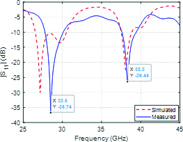
A prototype of the proposed dual-band Yagi–Uda antenna is fabricated for experimental verification of the simulation results concerning the dependence of the reflection coefficient on the frequency and the radiation patterns. The substrate used for fabrication is Rogers RO3003, with substrate height , dielectric constant and dielectric loss tangent . The same design dimensions given in section 4.1.1 are used for the fabrication process. Top and bottom views of the fabricated prototype are presented in Figure 14. The 2.4 mm end launch connector from Southwest Microwave Inc. is used to measure the port performance of the prototype antenna shown in Figure 14 using the vector network analyzer (VNA) from Rohde and Schwartz model ZVA67. After performing the required settings and calibration procedure, antenna prototype under test is connected to the VNA as shown in Figure 15 (a) and the return loss is measured. The result measurements are compared to that obtained by simulation using the CST software package and plotted in Figure 15 (b) showing good agreement. The measurement results for show that the proposed antenna has an impedance matching bandwidth of about 2.7 GHz (27.5-30.2 GHz) for reflection coefficient -10dB around the 28 GHz band, and 1.7 GHz (37.3-39 GHz) around the 38 GHz band.
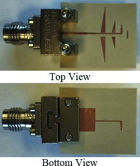
Fig. 14. Photograph of the fabricated prototype of the dual-band 28/38 GHz Yagi–Uda proposed for MIMO antenna systems of 5G mobile handsets.

(a)
(b)
Fig. 15. (a) Experimental setup for measuring the return loss of the dual-band antenna. (b) Measured frequency response of the return loss of the dual-band antenna compared with the simulation results.
D.1.2. Measurements of the radiation patterns and maximum gain
For experimental measurement of the radiation pattern of the fabricated dual-band antenna, the standard gain linear-polarized horn antenna model LB-018400 is used as a reference antenna and the experimental setup is made as shown in Figure 16. The measurements are performed in an anechoic chamber with the vector network analyzer Rohde and Schwartz model ZVA67. The distance between the reference antenna and the antenna under test is 60 cm. The radiation patterns are measured at 28 and 38 GHz in the two principal planes () and (). The radiation patterns obtained through simulation and experimental measurements are presented in Figure 17 showing good agreement. The measured maximum gain is 8.7 dB at 28 GHz and 9.5 dB at 38 Ghz.
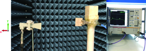
Fig. 16. Experimental setup for measuring the radiation pattern and gain of the dual-band antenna.
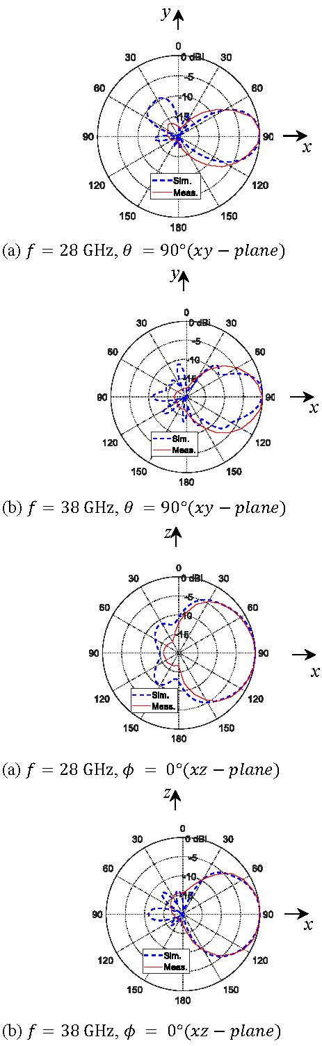
Fig. 17. Measured radiation patterns of the dual-band antenna compared with the simulation results.
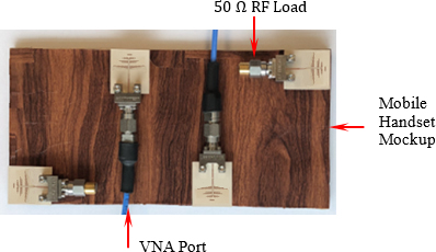
Fig. 18. Fabricated prototype for the four-port MIMO antenna system constructed on a mockup with four Yagi–Uda antennas arranged on the edges.
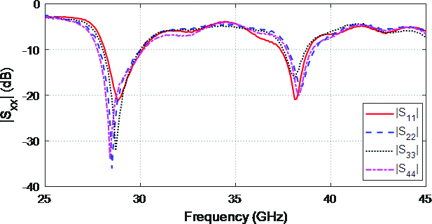
Fig. 19. Measured frequency response of the return loss of the four-port MIMO antenna system.
D.2. Fabrication and measurements of the MIMO antenna system
In this section, the proposed dual-band antenna is employed to construct a four-port MIMO antenna system mobile handset antenna mockup as shown in Figure 18. The mockup is constructed of a solid rectangle shape of dimensions with four openings of the same size as the single antenna at the specified locations shown in Figure 3 with and . The four-port MIMO antenna system mounted on the antenna mockup is shown in Figure 18. The 2.4 mm end launch connectors from Southwest Microwave Inc. are used for measuring the return loss of each antenna and the mutual coupling between each antenna pair using the VNA Rhode & Schwartz model ZVA67. During the measurement process, loads are connected to the elements not under test to avoid their effects. Figure 19 illustrates the measured return loss for each antenna in the frequency band 25-45 GHz. It is evident that the MIMO antenna system exhibits good impedance matching at both the operating frequencies 28 and 38 GHz. The mutual coupling coefficients are measured and plotted as shown in Figure 20. It is clear that the MIMO antenna system has very low mutual coupling -38dB over the entire frequency range.
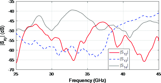
Fig. 20. Measured frequency response of the mutual coupling coefficient of the four-port MIMO antenna system.
V. CONCLUSIONS
An enhanced modified Yagi–Uda antenna design is introduced for the 28/38 GHz dual-band operation. The antenna is constructed from a driving corrugated dipole and a capacitively end-coupled extension strip with two reflectors and one director. A four-port MIMO antenna system for mobile handsets is constructed using the proposed Yagi–Uda. Numerical and experimental investigations are achieved to assess the performance of both the single antenna and the four-port MIMO antenna system. It is shown that the simulation results agree with the experimental measurements and both show good performance of the single antenna as well as the MIMO antenna system. The bandwidths achieved around 28GHz and 38GHz are about 4GHz and 1.5GHz, respectively. The four-antenna configuration shows radiation pattern diversity which is required for MIMO system operation. The calculated envelope correlation coefficient (ECC) and diversity gain (DG) show that the proposed MIMO antenna system can serve as a mobile phone antenna.
REFERENCES
[1] T. S. Rappaport, S. Sun, R. Mayzus, H. Zhao, Y. Azar, K. Wang, G. N. Wong, J. K. Schulz, M. Samimi, and F. Gutierrez, “Millimeter wave mobile communications for 5G cellular: it will work!,” IEEE Access, vol. 1, pp. 335-349, 2013.
[2] T. S. Rappaport, F. Gutierrez, E. Ben-Dor, J. N. Murdock, Y. Qiao, and J. I. Tamir, “Broadband millimeter-wave propagation measurements and models using adaptive-beam antennas for outdoor urban cellular communications,” IEEE Trans. Antennas Propag., vol. 61, no. 4, pp. 1850-1859, 2013.
[3] C. Narayan, Antennas and Propagation. Technical Publications, 2007.
[4] A. V. Alejos, M. G. Sanchez, and I. Cuinas, “Measurement and analysis of propagation mechanisms at 40 ghz: viability of site shielding forced by obstacles,” IEEE Trans. Veh. Technol., vol. 57, no. 6, pp. 3369-3380, 2008.
[5] S. Rajagopal, S. Abu-Surra, Z. Pi, and F. Khan, “Antenna array design for multi-gbps mm wave mobile broadband communication,” in Global Telecommunications Conference (GLOBECOM). IEEE, pp. 1-6, 2011.
[6] A. I. Sulyman, A. T. Nassar, M. K. Samimi, G. R. MacCartney, T. S. Rappaport, and A. Alsanie, “Radio propagation path loss models for 5G cellular networks in the 28 GHz and 38 GHz millimeterwave bands,” IEEE Communications Magazine, vol. 52, pp. 78-86, 2014.
[7] M. S. Sharawi, S. K. Podilchak, M. T. Hussain, and Y. M. M. Antar, “Dielectric resonator based MIMO antenna system enabling millimeter-wave mobile devices,” IET Microwaves, Antennas & Propagation, pp. 287-293, 2017.
[8] D. T. T. Tu, N. G. Thang, and N. T. Ngoc, “28/38 GHz dual-band MIMO antenna with low mutual coupling using novel round patch EBG cell for 5G applications,” International Conference on Advanced Technologies for Communications, 2017.
[9] A. E. Farahat and K. F. A. Hussein, “Dual-band (28/38 GHz) MIMO antenna system for 5G mobile communications with efficient DoA estimation algorithm in noisy channels,” Applied Computational Electromagnetics Society (ACES) Journal, vol. 36, no. 3, Mar. 2021.
[10] J.-F. Li and Q.-X. Chu “A compact dual-band MIMO antenna of mobile phone,” J. of Electromagn. Waves and Appl., vol. 25, pp. 1577-1586, 2011.
[11] M. M. Amin, M. Mansor, N. Misran, and M. Islam, “28/38 GHz dual band slotted patch antenna with proximity-coupled feed for 5G communication,” 2017 International Symposium on Antenna and Propagation (ISAP), pp. 1-2, 2017.
[12] M. I. Khattak, A. Sohail, U. Khan, Z. Barki, and G. Witjaksono, “Elliptical slot circular patch antenna array with dual band behavior for future 5G mobile communication networks,” Progress In Electromagnetics Research C, vol. 89, pp. 133-147, 2019.
[13] O. M. Haraz, M. M. M. Ali, S. Alshebeili, and A.-R. Sebak, “Design of a 28/38 GHz dual-band printed slot antenna for the future 5G mobile communication networks,” The 2015 IEEE AP-S Symposium on Antennas and Propagation and URSI CNC/USNC Joint Meeting, 2015.
[14] P. R. Grajek, B. Schoenlinner, and G. M. Rebeiz, “A 24-GHz high-gain Yagi-Uda antenna array,” IEEE Trans. Antennas Propag., vol. 52, pp. 1257-1261, May 2004.
[15] S. X. Ta, S.-g. Kang, J. J. Han, and I. Park, “High-efficiency, high-gain, broadband quasi-yagi antenna and its array for 60-GHz wireless communications,” Journal of Electromagnetic Engineering and Science, vol. 13, no. 3, pp. 178-185, Sep. 2013.
[16] X. Y. Wu and P. S. Hall, “Substrate integrated waveguide Yagi-Uda antenna,” Electronics Letters, vol. 46, no. 23, pp. 1541-1542, Nov. 2010.
[17] A. E. Farahat and K. F. A. Hussein, “28/38 GHz dual-band Yagi-Uda antenna with corrugated radiator and enhanced reflectors for 5G MIMO antenna systems,” Progress In Electromagnetics Research, vol. 101, pp. 159-172, 2020.
[18] M. R. Naeini and M. Fakharzadeh, “A 28 GHz beam-switching Yagi-Uda array using rotman lens for 5G wireless communications,” International Symposium on Antennas and Propagation & USNC/URSI National Radio Science, 2017.
[19] M. Lin, P. Liu, and Z. Guo, “Gain-enhanced Ka-band MIMO antennas based on the SIW corrugated technique,” IEEE Antennas Wirel. Propag. Lett., vol. 16, pp. 3084-3087, 2017.
BIOGRAPHIES

Asmaa E. Farahat received her B.Sc. and M.Sc. in the Department of Biomedical Engineering, Faculty of Engineering, Cairo University, 2002 and 2006, respectively. She received the PhD in 2012, Ain Shams University. She is currently associate professor at the Department of Microwave Engineering at the Electronics Research Institute. She has work experience in scientific research for about 17 years. She has published more than 28 papers in international, regional, and local scientific journals and conferences. She has worked as secondary investigator for three research projects. Her research interests are in the areas of antennas, electromagnetic wave propagation, risk assessment of human exposure to microwave radiation, remote sensing systems, and radar systems.

Khalid F.A. Hussein received his B.Sc., M.Sc., and Ph.D. degrees in the Department of Electronics and Electrical Communications, Faculty of Engineering, Cairo University, 1990, 1995, and 2001, respectively. He is currently a professor at the Department of Microwave Engineering at the Electronics Research Institute. He has work experience in scientific research for more than 30 years. He has more than 20 years’ experience in teaching in engineering colleges under many universities. He has supervised more than 70 doctoral and master theses. He has published more than 100 papers in international, regional, and local scientific journals and conferences. He has served as the Head of Microwave Engineering Department at the Electronics Research Institute for up to four years. He has been a Member of the Egyptian Space Program (currently the Egyptian Space Agency) for more than eight years. He has worked as Principal Investigator for four research projects and Head of Research Group in four other research projects. He designed and implemented several satellite antennas between prototypes and finished products. He has provided scientific consultations and conducted field measurements related to the design and distribution of mobile communication base station antennas for good signal coverage in behalf of many Egyptian and international companies. His research interests are in the areas of antennas, electromagnetic wave propagation, risk assessment of human exposure to microwave radiation, optical communications, photonics, quantum computing, radar systems, particularly ground penetrating radar (GPR), synthetic aperture radar (SAR), and remote sensing systems.
ACES JOURNAL, Vol. 36, No. 10, 1325–1334.
doi: 10.13052/2021.ACES.J.361009
© 2021 River Publishers