A Dual-Array Antenna System for 5G Millimeter-Wave Applications
Hafiz Usman Tahseen1, Lixia Yang2, and Wang Hongjin1
1School of Computer Science and Communication Engineering
Jiangsu University, Zhenjiang, 212013, China
drengrtahseen@gmail.com, 2405302396@qq.com
2Department of Communication Engineering
Anhui University, Hefei, 230601, China
Lixiayang@yeah.net
Submitted On: March 3, 2021; Accepted On: July 7, 2021
Abstract
Millimeter-wave (mm-Wave) technology has opened a new era of wireless communication systems in various fields like automotive, mobile devices, Internet of Things (IoT), military, medical, and others. The benefit of adopting the unconventional frequency spectrum of large bandwidth under an mm-Wave spectrum is the availability of large bandwidth and lesser chances of interferences from various technologies. In the recent 5G communication systems either cellular or other wireless applications, many researchers have focused on mm-Wave antennas and arrays. In this paper, a dual-array antenna system is designed for various 5G mm-Wave wireless applications. It has two arrays on the same substrate edges with a series feed line compact technique. The profile antenna system has two 1×16 arrays on the same substrate edges. Each array gives 17.3 dB and 16.4 dB simulated and measured gains and impedance bandwidth 31.30 GHz to 39 GHz at 38 GHz center frequency. The feature to use both arrays at the same time for two different applications within the operational band for same or different center frequencies makes this proposed dual-array antenna system a good candidate for 5G mm-Wave wireless IoT and broadcast applications.
Index Terms: Internet of Things (IoT), antenna array, millimeter-wave (mm-Wave).
I. INTRODUCTION
The technological development in cellular devices, androids, and broadcast applications with the passage of time has inspired a high-speed data rate demand that leads to a 5G communication system. The high frequency bands in millimeter-wave (mm-Wave) range, i.e., n258, n257, n261, n260, n260, and n257 have already been allocated by the FCC for 5G communication systems.
The three main factors, i.e., arbitrary mobile device orientation, indoor outdoor propagation environment, and user mobility are really important for designing antennas in cellular communication systems [1]. The high path losses in communication systems are due to the high operating frequencies that are compensated with high gain directional antennas [2]. The high frequency mm-Wave antennas provide high data rate in communication systems [3]. In high frequency communication systems, directional antenna is a good choice to reduce delay spread, Doppler shift spread, and path loss exponent [4]-[6]. The high frequency 5G antennas have become a hot topic these days for wireless networks that cover multiple bands with wide bandwidths [7]. In [8], a proximity-coupled planar antenna array is presented that gives 21 dBi high gain with impedance bandwidth 27.5–28.5 GHz for cellular 5G applications. In [1], a multi-mode phased antenna array is proposed to cover the frequency band 25–33 GHz. In [9], the 8-element antenna array is designed for 5G wireless cellular applications that give 12 dBi gain with 26.5–38 GHz impedance bandwidth with low side lobes. In [10]-[21], a substrate integrated waveguide (SIW) feed network is used to get large impedance bandwidth and high gain. In [22], A SIW-fed 8×8 antenna array is presented that gives 26.7 dBi gain with impedance bandwidth 35.4–41.7 GHz. A series-parallel feeding technique is preferred instead of traditional parallel power divider networks for tight planar array configurations and compact sizes [23]. A novel method is used in [24] to reduce mutual reduction in 8-element antenna array that gives 11.32 dBi gain with the impedance bandwidth 24.75–28.5 GHz.
This article presents a dual-array antenna system with a compact feeding network for various 5G mm-wave multiple wireless applications as shown in Figure 1. The compact feeding structure is based on a series-parallel technique as in [23].

Fig. 1. 5G antennas; (a) single antenna element, (b) 1×4 antenna array, (c) 1×16 antenna array.
All patch elements are in parallel connection with a single series feed line. So, they all are excited with a single port. The profile antenna element has a half-moon slot at the center and is excited at 38 GHz center frequency antenna to operate for n260 5G band for high-speed data rate applications. Each array exhibits equal broad bandwidth with high gain and negligible side lobes. There is a little drop or discrimination of gain at edge frequencies for the entire bandwidth.
The operation of dual-array antenna structure with compact feed network for two different applications at the same or different frequencies within the operational band makes this proposed array a good candidate for multi-wireless mm-Wave applications. The profile 1×16 dual-array antenna can be used for Internet of Things (IoT) and cellular applications in smartphones with two 1×4 antenna arrays for end-fire coverage. Furthermore, the proposed 1×16 dual-array antenna is also a good candidate for indoor and outdoor mm-Wave broadcast and IoT applications. The simulation results from ANSYS 18.2 HFSS are compared with the measured results for validity check.
The paper is organized as follows: section II discusses the antenna design and principle of operation. Results and discussions lie in section III. Final summary is in section IV.

Fig. 2. Single element antenna results; (a) realized gain, (b) simulated reflection coefficient without slot, (c) simulated reflection coefficient with half-moon slot.
II. ANTENNA DESIGN AND PRINCIPLE
A. Antenna design
It is really important to design a broadband mm-Wave antenna element with high gain for array configuration as shown in Figure 1. In the first step, an antenna element is simulated without any slot on the patch at 38 GHz center frequency on a Rogers-5880 dielectric substrate with basic micro strip antenna design formulae as follows in [25, 26]. The antenna element gives 7.15 dBi gain with impedance bandwidth 36.16–39.27 GHz with 32.78 dB return loss as shown in Figure 2 (a) and (b). In the 2nd step, a half-moon slot is added on the patch to improve the bandwidth. The antenna parameters are mentioned in Table 1. The antenna element with half-moon slot gives an improved bandwidth 31.30–39 GHz at 38 GHz center frequency as shown in Figure 2 (c).
Firstly, a 1×4 array is simulated at 38 GHz center frequency as shown in Figure 1 (b) for demonstration and then two 1×16 antenna arrays on the same substrate edges are designed. Each array has a separate feed port. The antenna elements are connected in a compact series feed line mechanism. Each series feed line has an mm-Wave port connector at the center.
Table 1: Specifications of antenna element
| No. | Description | Units/quantity |
| 1 | Patch length | 2.34 mm |
| 2 | Patch width | 3.12 mm |
| 3 | Substrate length | 5.43 mm |
| 4 | Substrate width | 4.21 mm |
| 5 | Substrate height | 0.5 mm |
| 6 | Feed line length | 2.413 mm |
| 7 | Feed line width | 0.543 mm |
| 8 | Inset gap | 0.1003 mm |
| 9 | Moon slot radius | 0.4 mm |
| 10 | Series line width | 0.543 mm |
| 11 | Frequency | 38 GHz |
B. Dual-array antenna
With the optimized configuration of antenna element, a dual-array mm-Wave 5G antenna is designed with high gain and large bandwidth. The antenna array with 4-element configuration is simulated for array demonstration. The main dual-array antenna consists of two 1×16 antenna arrays on a single substrate edge in the broadside direction with two separate ports. The proposed dual-array antenna can be used for mm-Wave 5G multi-wireless applications. It is also applicable to mm-Wave 5G base stations, broadcast, and IoT applications. So, the proposed dual-array antenna structure looks a good candidate for strong signal coverage for 5G applications. The antenna uses Rogers-5880 dielectric substrate with 0.5 mm height, 0.002 loss tangents, and 2.2 relative permittivity. Each antenna element has dimensions as mentioned in Table 1. The substrate size of 1×4 antenna array is 3.43 mm × 29.80 mm × 0.5 mm and each 1×16 antenna array has 29.80 mm × 90.49 mm × 0.5 mm dimensions. The antenna array elements are spaced and are connected with a series feed line mechanism.
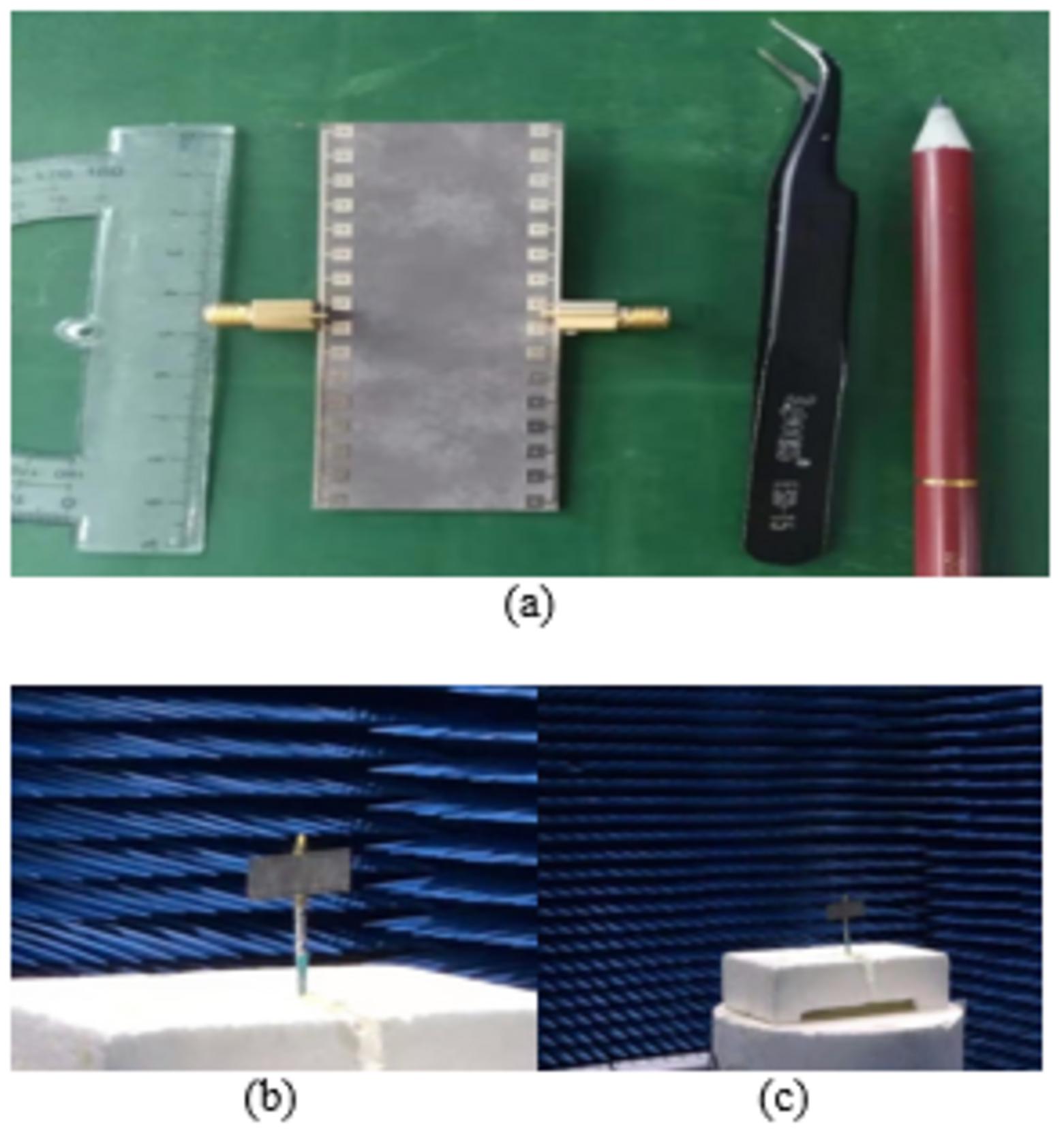
Fig. 3. Fabricated dual antenna array; (a), (b), and (c).
III. RESULTS AND DISCUSSIONS
The proposed dual-array antenna system is a prototype as shown in Figures 3 (a) and (b). In dual-array antenna system, each array is connected to a 2.92k mm-Wave connector separately. Each 1×16 antenna array exhibits high gain with a large impedance bandwidth in mm-Wave frequency range. Firstly, a single patch element is simulated without any slot. It gives a wide radiation pattern with narrow bandwidth. In the next step, a half-moon slot is added on the patch to improve the band width as shown in Figures 2 (a), (b), and (c).
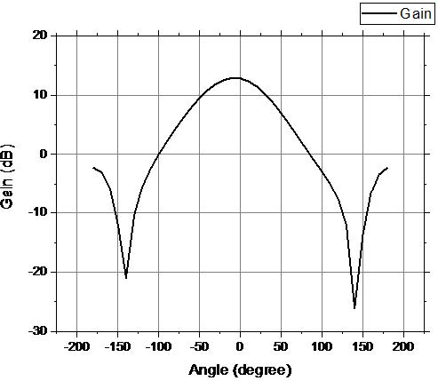
Fig. 4. Simulated realized gain of 1×4 antenna array.
Secondly, a 1×4 antenna array is simulated for array description, design confirmation, and end-fire coverage demonstration for smartphone application. The 1×4 antenna array exhibits 12.91 dB simulated gain as shown in Figure (4). With these parameters, a dual-array antenna with two 1×16 antenna arrays is simulated and then fabricated for mm-Wave 5G multi-wireless applications. It exhibits high gain with large impedance bandwidth. In dual-array antenna system, both arrays give almost the same radiation pattern and impedance bandwidth. Figure 5 shows the simulated and measured radiation patterns for one of the 1×16 antenna arrays at 38 GHz center frequency. The plot in Figure 6 gives the measured and simulated reflection coefficient of 1×16 antenna array with the impedance bandwidth 31.30–39 GHz. It shows that the profile dual-array antenna system with a compact feed mechanism is a good candidate to achieve broad bandwidth. There is no evident influence looks on antenna performance from simulated and measured results.
Figure 7 shows the measured and simulated antenna gains of the proposed dual-array antenna system for the entire bandwidth. It is clear that the gain slightly drops for the entire bandwidth. A little discrimination is observed between simulated and measured results due to the high-frequency mm-Wave connector and soldering effect.
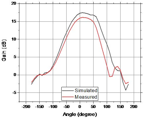
Fig. 5. Simulated and measured realized gain of 1×16 antenna array.
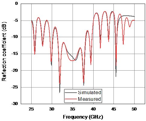
Fig. 6. Reflection coefficient of 1×16 antenna array.
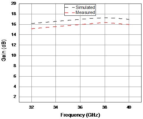
Fig. 7. Gain curve of 1×16 antenna array.
IV. CONCLUSION
This paper presents a design of dual-array antenna system with compact feed network. The profile antenna array structure is based on a series feed mechanism for a tight planar configuration, easy fabrication, and broad bandwidth. It is applicable to where compact size is required. Both arrays can be operated for two different applications within the operational band for same or different center frequencies for cellular, IoT, and different broadcast mm-Wave applications. This makes the proposed dual-array antenna system a good candidate for 5G mm-Wave multi-wireless applications. It may further be enhanced for phased antenna array cellular applications. A good agreement between measured and simulated results makes this profile dual-array antenna structure suitable for mm-Wave 5G multi-wireless applications.
ACKNOWLEDGMENT
This paper is supported by National Science Foundation of China under Grant 62071003, Grant 41874174, Grant 61901004, and Grant 61801194, the Opening Foundation of National Key Laboratory of Electromagnetic Environment under Grant 201802003, the fund for key Laboratory of Electromagnetic scattering under Grant 61424090107, and the Natural Science Foundation of Anhui Province under Grant 2008085MF186.
REFERENCES
[1] I. Syrytsin, S. Zhang, G. F. Pedersen, and A. Morris, “Compact quad-mode planar phased array with wideband for 5G mobile terminals,” IEEE Transactions on Antennas and Propagation, vol. 66, no. 9, pp. 4648-4657, Sep. 2018.
[2] W. Roh, J. Y. Seol, J. Park, B. Lee, J. Lee, Y. Kim, J. Cho, K. Cheun, and F. Aryanfar, “Millimeter-wave beam forming as an enabling technology for 5G cellular communications: theoretical feasibility and prototype results,” IEEE Commun. Mag., vol. 52, pp. 106-113, Feb. 2014.
[3] M. S. Sharawi, M. Ikram, and A. Shamim, “A two concentric slot loop based connected array MIMO antenna system for 4G/5G terminals,” in IEEE Transactions on Antennas and Propagation, vol. 65, no. 12, pp. 6679-6686, Dec. 2017, doi: 10.1109/TAP.2017.2671028.
[4] S. J. Nawaz, N. M. Khan, M. N. Patwary, and M. Moniri, “Effect of directional antenna on the doppler spectrum in 3-D mobile radio propagation environment,” IEEE Trans. Veh. Technol., vol. 60, no. 7, pp. 2895-2903, 2011.
[5] T. Manabe, Y. Miura, and T. Ihara, “Effects of antenna directivity and polarization on indoor multipath propagation characteristics at 60 GHz,” IEEE Journal on Selected Areas in Communications, vol. 14, pp. 441-448, Apr. 1996.
[6] Y. Azar, G. N. Wong, K. Wang, R. Mayzus, J. K. Schulz, H. Zhao, F. Gutierrez, D. Hwang, and T. S. Rappaport, “28 GHz propagation measurements for outdoor cellular communications using steerable beam antennas in New York city,” IEEE International Conference on Communications (ICC), pp. 5143-5147, 2013.
[7] J. G. Andrews, S. Buzzi, W. Choi, S. V. Hanly, A. Lozano, A. C. K. Soong, and J. C. Zhang, “What will 5G be?,” IEEE Journal on Selected Areas in Communications, vol. 32, no. 6, pp. 1065-1082, Jun. 2014.
[8] H. A. Diawuo and Y. Jung, “Broadband proximity-coupled microstrip planar antenna array for 5G cellular applications,” in IEEE Antennas and Wireless Propagation Letters, vol. 17, no. 7, pp. 1286-1290, July 2018, doi: 10.1109/LAWP.2018. 2842242.
[9] S. X. Ta, H. Choo, and I. Park, “Broadband printed-dipole antenna and its arrays for 5G applications,” in IEEE Antennas and Wireless Propagation Letters, vol. 16, pp. 2183-2186, 2017, doi: 10.1109/LAWP.2017.2703850.
[10] Y. Li and K.-M. Luk, “Wide band perforated dense dielectric patch antenna array for millimeter-wave applications,” IEEE Trans. Antennas Propag., vol. 63, no. 8, pp. 3780-3786, Aug. 2015.
[11] Y. Li and K.-M. Luk, “Low-cost high-gain and broadband substrate integrated-waveguide-fed patch antenna array for 60-GHz band,” IEEE Trans. Antennas Propag., vol. 62, no. 11, pp. 5531-5538, Nov. 2014.
[12] Q. Zhu, K.-B. Ng, and C. H. Chan, “Printed circularly polarized spiral antenna array for millimeter-wave applications,” IEEE Trans. Antennas Propag., vol. 65, no. 2, pp. 636-643, Feb. 2017.
[13] Y. Li and K.-M. Luk, “60-GHz substrate integrated waveguide fed cavity backed aperture-coupled micro strip patch antenna arrays,” IEEE Trans. Antennas Propag., vol. 63, no. 3, pp. 1075-1085, Mar. 2015.
[14] H. Jin, W. Che, K. S. Chin, W. Yang, and Q. Xue, “Millimeter-wave TE20 mode SIW dual-slot-fed patch antenna array with a compact differential feeding network,” IEEE Trans. Antennas Propag., vol. 66, no. 1, pp. 456-461, Jan. 2018.
[15] Y. Li and K.-M. Luk, “60-GHz dual-polarized two-dimensional switch beam wideband antenna array of aperture-coupled magneto-electric dipoles,” IEEE Trans. Antennas Propag., vol. 64, no. 2, pp. 554-563, 2016.
[16] J. Xu, Z. N. Chen, X. Qing, and W. Hong, “Bandwidth enhancement for a 60 GHz substrate integrated waveguide fed cavity array antenna on LTCC,” IEEE Trans. Antennas Propag., vol. 59, no. 3, pp. 826-832, Mar. 2011.
[17] W. Yang, H. Wang, W. Che, Y. Huang, and J. Wang, “High-gain and low-loss millimeter-wave LTCC antenna array using artificial magnetic conductor structure,” IEEE Trans. Antennas Propag., vol. 63, no. 1, pp. 390-395, Jan. 2015.
[18] J. Xu, Z. N. Chen, X. Qing, and W. Hong, “140-GHz TE20-mode dielectric-loaded SIW slot antenna array in LTCC,” IEEE Trans. Antennas Propag., vol. 61, no. 4, pp. 1784-1793, Apr. 2013.
[19] H. Jin, W. Che, K. S. Chin, G. Shen, W. Yang, and Q. Xue, “60-GHz LTCC differential-fed patch antenna array with high gain by using soft-surface structures,” IEEE Trans. Antennas Propag., vol. 65, no. 1, pp. 206-216, 2017.
[20] B. Cao, H. Wang, Y. Huang, and J. Zheng, “High-gain L-probe excited substrate integrated cavity antenna array with LTCC-based gap waveguide feeding network for W-band application,” IEEE Trans. Antennas Propag., vol. 63, no. 12, pp. 5465-5474, Dec. 2015.
[21] J. Xu, Z. N. Chen, X. Qing, and W. Hong, “140-GHz planar broadband LTCC SIW slot antenna array,” IEEE Trans. Antennas Propag., vol. 60, no. 6, pp. 3025-3028, Jun. 2012.
[22] X. Li, J. Xiao, Z. Qi, and H. Zhu, “Broadband and high-gain SIW-fed antenna array for 5G applications,” in IEEE Access, vol. 6, pp. 56282-56289, 2018, doi: 10.1109/ACCESS.2018.2873392.
[23] H. A. Diawuo and Y. Jung, “Broadband proximity-coupled microstrip planar antenna array for 5G cellular applications,” in IEEE Antennas and Wireless Propagation Letters, vol. 17, no. 7, pp. 1286-1290, July 2018, doi: 10.1109/LAWP.2018.2842242.
[24] S. Zhu, H. Liu, Z. Chen, and P. Wen, “A compact gain-enhanced vivaldi antenna array with suppressed mutual coupling for 5G mmWave application,” in IEEE Antennas and Wireless Propagation Letters, vol. 17, no. 5, pp. 776-779, May 2018, doi: 10.1109/LAWP.2018.2816038.
[25] R. Garg, Microstrip Antenna Design Handbook, Reading, MA: Artech House, Boston, 2011.
[26] C. A. Balanis, Antenna Theory: Analysis and Design, Third Edition, John Wiley & Sons, Inc., Publication, New Jersey, 2005.
BIOGRAPHIES

Hafiz Usman Tahseen was born in 1983 in Pakistan. He completed his graduation and then Masters in Electronic Engineering in 2017 from University of Engineering and Technology Lahore, Pakistan. He further completed his Ph.D. in Communication Engineering in 2021 from Jiangsu University, China. He is now with the School of Computer Science and Communication Engineering, Jiangsu University, China.

Lixia Yang born in Ezhou, Hubei, China, in 1975. He received his B.S. degree in Physics from Hubei University, Wuhan, China, in 1997, and Ph.D. degree in Radiophysics from Xidian University, Xi’an, China, in 2007. Since 2010, he has been an Associate Professor with the Communication Engineering Department, Jiangsu University. During 2010–2011, he was a Postdoctoral Research Fellow with the Electro Science Laboratory (ESL), The Ohio State University. During 2015–2016, he was a Visiting Scholar with the Institute of Space Science, The University of Texas, Dallas, TX, USA. Since 2016, he has been a Professor, a Ph.D. Supervisor, and the Chairman of the Communication Engineering Department, Jiangsu University. He is the author of a book and more than 100 articles, and has more than 10 inventions in his name. He holds four patents. His research interests include wireless communication technique, radio sciences, computational electromagnetics, and the antenna theory and design in wireless communication systems. He is a member of the Editor Board of Radio Science Journal in China.
ACES JOURNAL, Vol. 36, No. 10, 1319–1324.
doi: 10.13052/2021.ACES.J.361008
© 2021 River Publishers