Quad-Band MIMO Antenna System for 5G Mobile Handsets
M. Abo El-Hassan, A. E. Farahat, and K. F. A. Hussein
Electronics Research Institute (ERI), Cairo, Egypt
mayaboelhassan@yahoo.com, asmaa@eri.sci.eg, Khalid_elgabaly@yahoo.com
Submitted On: March 22, 2021; Accepted On: August 1, 2021
Abstract
An efficient Multi-Input Multi-Output (MIMO) antenna system with a spatial diversity configuration for the Fifth Generation (5G) mobile handsets is constructed from a compact-size quad-band () microstrip patch antennas. The antenna is constructed as primary and secondary patches which are capacitively coupled and designed to realize impedance matching and to produce appropriate radiation patterns in the four frequency bands. The novel quad-band patch antenna includes complicated radiation mechanisms required for multiple-band operation. Two-port and four-port MIMO antenna systems that employ the quad-band patch antenna are proposed in the present work for the 5G mobile handsets. Numerical and experimental investigations are achieved to assess the performance of both the single-element antenna and the proposed MIMO antenna systems including the return loss at each antenna port and the coupling coefficients between the different ports. It is shown that the simulation results agree with the experimental measurements and both show good performance. The bandwidths achieved around , , , and are about , , , and , respectively. The radiation patterns produced when each port is excited alone are shown to be suitable for spatial diversity scheme with high radiation efficiency. It is shown that the envelope correlation coefficient (ECC) and the diversity gain (DG) are perfect over the four frequency bands.
Index Terms: MIMO antenna, diversity gain, quad-band antenna.
I. INTRODUCTION
The further Fifth Generation (5G) of mobile communications will make the spectrum allocation more efficient [1, 2, 3, 4]. The unused millimeter-wave (mm-wave) electromagnetic spectrum (30–300 GHz) has attracted the attention and has been introduced as a candidate for the 5G mobile communication to enable multi-Gbit/s transmission rate exploiting the wide available bandwidth to meet the demands of the future applications which require high quality and low latency transmission and, hence, it is able to handle much greater capacity than the available 4G networks.
The mm-wave frequency bands centered at 28, 38, 60, and 73 GHz have been allocated for 5G mobile communications by International Telecommunications Union (ITU) [2]. Bands of 59–64 GHz are allocated by the Federal Communications Commission (FCC) as an unlicensed band for short range and wireless communications of high speeds [3, 4]. Some of the expected mm-wave bands recommended for 5G mobile communications are: , , , , , and [1]. Significant attenuation is caused by oxygen molecules in the atmosphere to react with mm-wave signals and reaches up to 10 dB km especially for the frequencies higher than 45 GHz. Due to this defect, it is not recommended to operate at frequencies that are much higher than 45 GHz for communication applications and long-range radar. For cellular mobile communications, the 28 GHz band is advantageous due to its low oxygen absorption rates unlike the higher mm-wave frequencies especially in 60 GHz band. The operation in the frequency bands higher than 45 GHz is recommended for short-range communications such as the Wi-Fi (with the WiGig standard in the 60 GHz band) [1, 5].
Due to the short wavelength of the mm-waves, the employment of spatial, pattern and polarization diversity techniques, such as Multi-Input Multi-Output (MIMO) is highly recommended for future generations of wireless communication systems that enable several Gb/s communication speed. In a MIMO antenna system, high radiation efficiency and high isolation between the multiple ports are required. Recently, a lot of research work has provided many designs for single-element antenna as well as MIMO antenna systems for 5G mobile handsets are demonstrated in this paragraph. For example, the work of [3] introduces a antenna consisting of H-shaped and E-shaped slots on the radiating patch. The work of [1] presents a dual-band circular microstrip patch antenna with an elliptical slot. This antenna operates at frequencies of 28 GHz and 45 GHz, with bandwidths of 1.3 GHz and 1 GHz. In [6], a printed planar Yagi–Uda antenna is introduced for dual-band operation at. In the same work, a four-port MIMO antenna system is constructed using the proposed Yagi–Uda antenna arranged at the edges of the mobile handset to provide pattern and polarization diversities. In [7], a four-port MIMO antenna is proposed, where each antenna has an end-fire gain of about to provide pattern and polarization diversities. The work of [8] introduces a compact microstrip line fed dual-band printed four-port MIMO antennas resonating at 28 GHz and 38 GHz to provide spatial diversity. In [9], a compact dual-band (38/60 GHz) microstrip patch antenna is proposed for 5G mobile handsets. In [10], a dual-band () microstrip patch antenna and a 4-element array are proposed to achieve gain for 5G mobile data applications. The work of [11] presents a compact MIMO antenna design with polarization and pattern diversity operating in the frequency band (34–38 GHz).
A computationally efficient electromagnetic (EM) solver can be used to solve the antenna problems such as the Method of Moments (MoM) solution of the Electric Field Integral Equation (EFIE) [12, 13, 14], or the Finite-Difference-Time-Domain (FDTD) [15]. The commercially available CST EM simulator combines the advantages of both techniques and is used in the present work for design and simulation of the proposed patch antenna and MIMO system.
The present work proposes two-port and four-port MIMO antenna systems for operation in the quad-band (). The MIMO antenna performance including the return loss at each antenna port and the coupling coefficients between the different ports is investigated and shown to be suitable for 5G mobile communications. The radiation patterns produced when each port is excited alone are shown to be suitable for an efficient diversity scheme. The performance measures such as the envelope correlation coefficient (ECC) and diversity gain (DG) are evaluated showing excellent performance of the proposed MIMO antenna systems.
The remaining part of the present paper is organized as follows. Section II provides the reduced-size patch antenna design to radiate at 28 GHz. Section III proposes two- and four-port MIMO antenna systems that employ spatial diversity for enhancement of the wireless channel performance. Section IV gives a summary of the proposed antenna performance and comparisons with some published designs. Finally, Section V provides the most important conclusions for the present work.
II. CONSTRUCTION OF QUAD-BAND PATCH ANTENNA
The geometry of the proposed quad-band antenna operating at 28, 45, 51, and 56 GHz bands is presented in Figure 1. The antenna structure can be viewed as composed of primary and secondary patches. The primary patch is responsible for radiation at and is excited through a microstrip line with inset feed. The secondary patch is capacitively coupled to the primary patch and can be considered as parasitic radiator. The composite structure of the dual-patch antenna is responsible for radiation at the other three frequency bands around, , and .
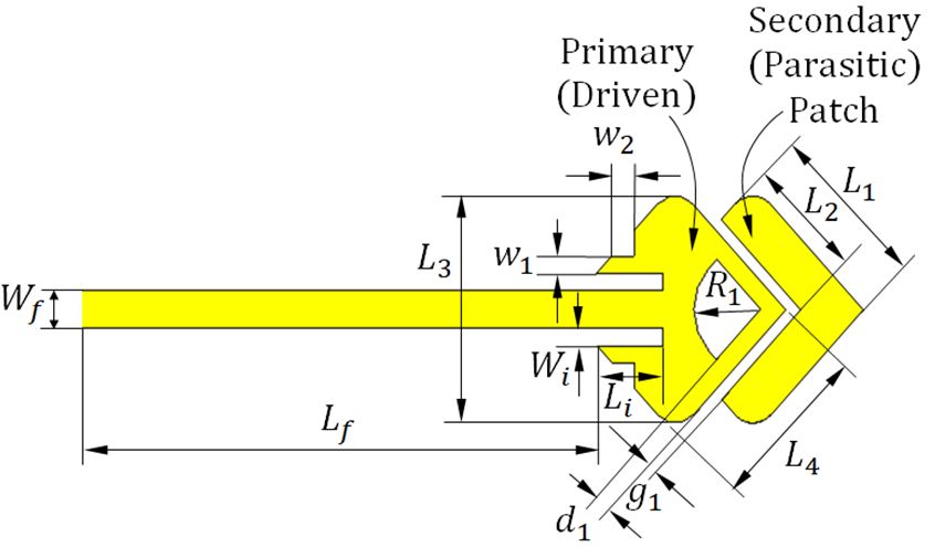
Fig. 1. Final geometry of the proposed quad-band patch antenna.
First, a rhombic patch antenna with right-angle corners is designed to operate at 28 GHz. If this patch is used to radiate at its higher-order resonances the resulting radiation patterns and the gain may not be appropriate for mobile applications due to the existing nulls and sidelobes. This is because the size of the 28 GHz patch is electrically large at the mm-wave frequencies higher than. It is expected that the higher the order of the radiating mode the larger the number of the nulls and sidelobes of the radiation pattern. The relatively large size of the conducting patch surface allows the formation of surface current patterns that result in radiation patterns with a number of nulls and sidelobes depending on the radiating mode order. Thus, if the area of the conducting patch surface is reduced the formed surface current patterns may result in acceptable shape of the radiation pattern and the maximum gain. The reduction of the area of the conducting surface of a rhombic patch (originally designed to radiate at 28 GHz) is performed by making some cuts in its geometry to remove the regions of negligible magnitude of the patch surface current formed at 28 GHz. This modified patch should not badly affect its performance at the principal resonant frequency (28 GHz). The smaller size of the geometrically modified patch antenna allows the excitation of higher-order resonances at higher frequencies with significantly improved shapes of the radiation patterns and acceptable values of the gain. To get the higher-order resonances located at the desired frequency bands, a secondary patch is added as parasitic radiator to act as a reactively coupled element of the appropriate geometry. The load impedance caused by such reactively coupled patch controls the locations of the higher-order resonant frequencies.
The antenna is fabricated on Rogers RO3003 substrate of height , dielectric constant = 3, and loss tangent =0.001. The substrate is placed over a solid ground plane. The feeding microstrip transmission line has a characteristic impedance of and dimensions of. An inset feed is used to match the antenna impedance to source. The corresponding values of the symbolic dimensional parameters of the antenna shown in Figure 7, are given in Table 1.
A. Numerical simulation and experimental assessment of the quad-band patch antenna
This section is concerned with the presentation of the results of numerical simulation and experimental measurements of the proposed quad-band microstrip patch antenna. To confirm the accuracy of the assessed performance for both the single-element and MIMO antennas, the experimental measurements are compared to those obtained by electromagnetic simulation using the commercially available CST software package. The prototype shown in Figure 2 is fabricated for this purpose. The antenna size is compared to the size of a coin of standard one-inch diameter. Excluding the microstrip line feeder, the outer dimensions of antenna are .
Table 1: Dimensions of the proposed antenna
| Dimension | ||||||
| Value (mm) | 3.14 | 2.15 | 3.86 | 2.88 | 0.4 | 0.62 |
| Dimension | ||||||
| Value (mm) | 0.3 | 1.29 | 0.63 | 9.98 | 0.28 | 0.48 |
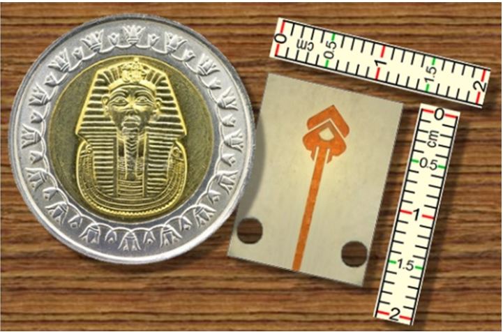
Fig. 2. Fabricated prototype of the proposed quad-band patch antenna with its size compared to a metal coin of standard size.
A1. Reflection coefficient at the antenna port
The vector network analyzer (VNA) of Rohde and Schwarz model ZVA67 is used for measuring the frequency response of the reflection coefficient magnitude. The end-launch connector from Southwest Microwave Inc. is used for connecting the antenna to the VNA as shown in Figure 3 (a).
The numerical simulation and experimental measurements for the frequency dependence of the magnitude of the reflection coefficient,, are presented in Figure 4. The experimental measurements show good agreement with the numerical results obtained by the CST simulator. It is clear that the antenna has excellent impedance matching over four frequency bands centered at 28, 45, 51, and 56 GHz where the value of is less than with respect to feeder.
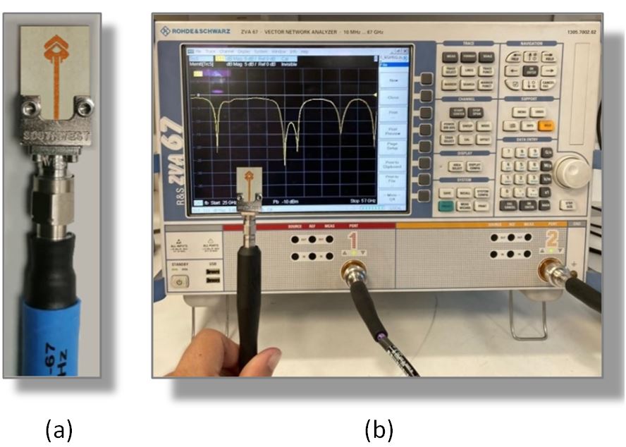
Fig. 3. Measurement of the reflection coefficient of the proposed quad-band patch antenna: (a) The fabricated prototype is connected to the end launcher, (b) The antenna is connected to the VNA of Rohde and Schwarz model ZVA67.
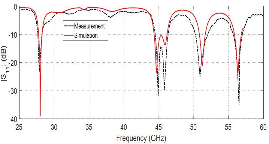
Fig. 4. Dependence of the reflection coefficient of the frequency for the proposed quad-band patch antenna.
A2. Radiation patterns of the quad-band patch antenna
The experimental setup for measuring the radiation patterns and the maximum gain of the proposed antenna is presented in Figure 5. The VNA Rohde and Schwarz model ZVA67 operating in the two-port measurement mode is used for this purpose by measuring the transmission coefficient through the antenna under test and the reference-gain linearly-polarized horn antenna models LB-018400 (for band) and LB-12-10-A (for band). The radiation patterns of the proposed antenna at 28, 45, 51, and 56 GHz are presented in Figures 6, 7, 8, and 9, respectively, in the elevation planes and . The experimental measurements show good agreement with the numerical results obtained by the CST simulation package. It is shown that the radiation patterns obtained at the four frequencies are acceptable and can be appropriate either for long-range or short-range communications.
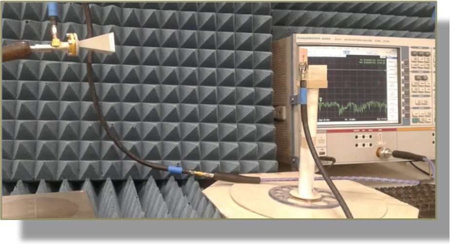
Fig. 5. Experimental setup for measuring the radiation pattern and gain of the quad-band antenna.
III. MIMO ANTENNA SYSTEMS USING THE QUAD-BAND PATCH ANTENNA
In this section, two-port and four-port MIMO antenna systems are constructed using the quad-band patch antenna. Prototypes of the proposed MIMO antennas are fabricated for the purpose of experimental assessment. The results of numerical simulation are compared to those of experimental measurements for the purpose of confirmation.
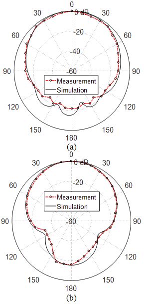
Fig. 6. Radiation patterns of the proposed quad-band patch antenna in the elevation planes (a) and (b) at .
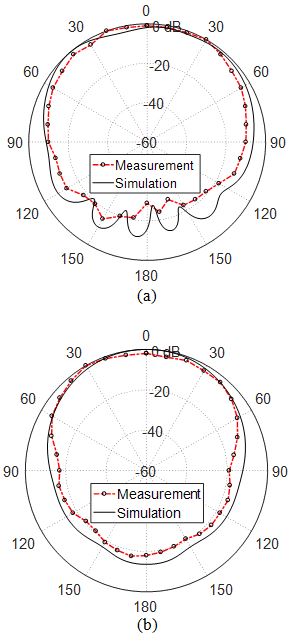
Fig. 7. Radiation patterns of the proposed quad-band patch antenna in the elevation planes (a) and (b) , at .
A. Two-port MIMO antennas using the quad-band patch antenna
Prototypes are fabricated for two-port MIMO antenna systems constructed as two elements of the proposed quad-band patch antenna using different configurations. The patches of the first MIMO system are arranged side-by-side as shown in Figure 10 (a). The patches of the other MIMO system are arranged face-to-face as shown in Figure 11 (a). A prototype is fabricated for each type of the MIMO antenna systems as shown in Figures 10 (b) and 11 (b), respectively, and connected to a coaxial feeder using coaxial end launchers for experimental assessment. The VNA of Rohde and Schwarz model ZVA67 is used to evaluate the transmission coefficient for the fabricated prototypes of the proposed MIMO antennas.
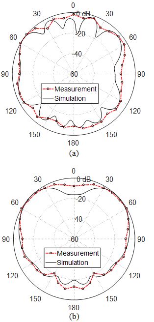
Fig. 8. Radiation patterns of the proposed quad-band patch antenna in the elevation planes and at .
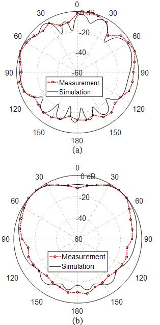
Fig. 9. Radiation patterns of the proposed quad-band patch antenna in the elevation planes and at .
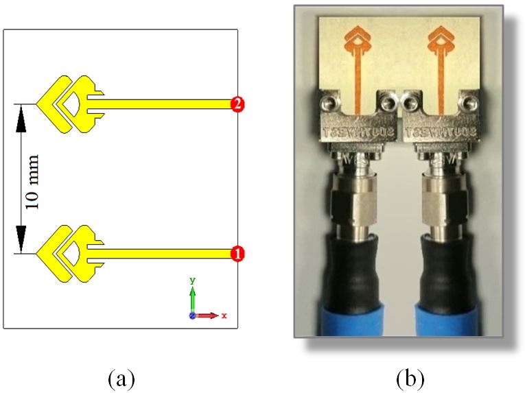
Fig. 10. Two-port MIMO antenna system constructed as two elements of the quad-band patch arranged side-by-side; (a) Model in the CST simulator, (b) Fabricated prototype is connected to end launchers and coaxial cables for measurements.
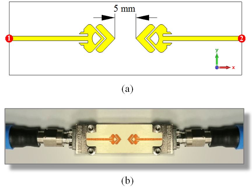
Fig. 11. Two-port MIMO antenna system constructed as two elements of the quad-band patch arranged face-to-face; (a) Model in the CST simulator, (b) Fabricated prototype is connected to end launchers and coaxial cables for measurements.
The frequency dependence of the coupling coefficient for each of the two-port MIMO configurations is presented in Figure 12. The experimental measurements show good agreement with the simulation results and both of them show that the antennas of each MIMO configuration are very weakly coupled where does not exceed –25 dB over the entire frequency range. It is clear that the coupling coefficients, , of the face-to-face MIMO configuration have larger magnitudes than those of the side-by-side MIMO configuration. This can be attributed to that the face-to-face configuration has narrower separation between the two antennas than that in the side-by-side configuration. Moreover, the face-to-face configuration allows higher rate of power transfer between the two antennas of the MIMO system because each antenna lies in the direction of the power flowing on the transmission line feeding the other antenna.
B. Four-port MIMO antenna system
To construct a four-port MIMO antenna system for operation at , , , and , four elements of the quad-band microstrip patch antenna with the dimensions listed in Table 1 are arranged as shown in the geometric model presented in Figure 13 for the MIMO antenna in the CST simulator. The separations between the four antennas are set so as to achieve the spatial diversity required for the target 5G applications. This design has total dimensions of . Such a MIMO antenna system can be practically suitable to be manufactured and integrated on a printed electronic board of a mobile handset.
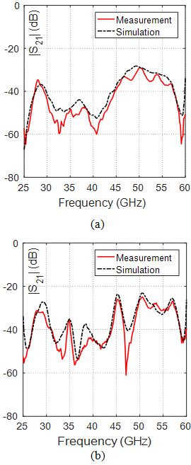
Fig. 12. Frequency responses of the coupling coefficient for the two-port MIMO configurations: (a) Side-by-Side configuration shown in Figure 10, (b) Face-to-face configuration shown in Figure 11.
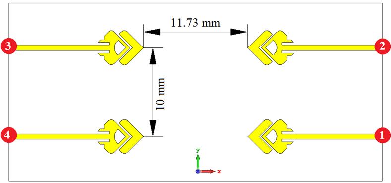
Fig. 13. Design of the quad-band four-port MIMO antenna system (total dimensions ) proposed for mobile handsets.
The prototype shown in Figure 14 is fabricated for the purpose of experimental assessment of the performance of the proposed quad-band four-port MIMO antenna system. The VNA Rohde and Schwarz model ZVA67 is used for measuring the frequency response of the reflection coefficients , , , , , and . Four end-launch connectors from Southwest Microwave Inc. are used for connecting the corresponding antenna ports to the VNA whereas the other two ports are connected to matched () loads as shown in Figure 14.
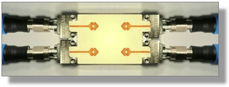
Fig. 14. Fabricated quad-band four-port MIMO system.
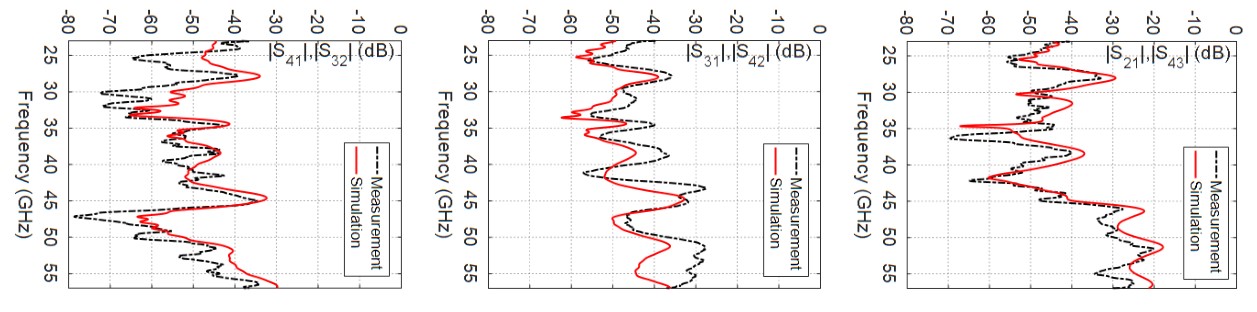
Fig. 15. The scattering parameters , , , , , and representing the different coupling coffiecients for the proposed MIMO antenna system.
B1. Coupling coefficients, envelop correlation coefficients, and diversity gain
The simulation results and experimental measurements describing the frequency dependence of the magnitudes of the scattering parameters , , , , , and representing the different coupling coefficients for the proposed quad-band four-port MIMO antenna system are presented in Figure 15. The simulation results appear to be in agreement with the results of the experimental measurements, and both of them show low values of the coupling coefficients.
The dependencies of the ECC and the DG of the proposed four-port MIMO antenna system on the frequency are presented in Figure 16. It is shown that at the operating frequencies , , , and and over the width of each of the four bands, the ECC is very low (almost 0) and, consequently, the DG is very high (almost 10). This can be considered as the optimum performance of MIMO antenna system. It should be noted that the relative positions of the antennas in the pair of ports (1,2) are the same as those in the pair of ports (3,4); this leads to identical ECC and DG as shown in Figure 16. The same applies for the antenna pairs (1,3) and (2,4) and, also, for the antenna pairs (1,4) and (2,3).
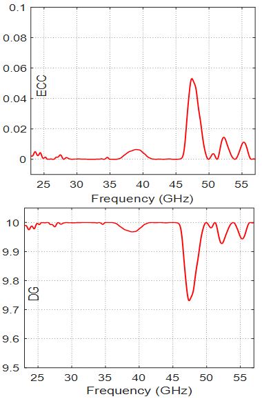
Fig. 16. Dependence of the ECC and DG on the frequency for the proposed quad-band four-port MIMO antenna system for ports (1,2) and (3,4).
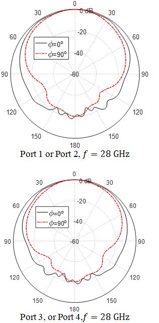
Fig. 17. Radiation patterns in the elevation planes for the quad-band MIMO antenna system at when excited at the indicated ports.
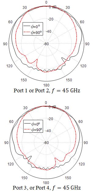
Fig. 18. Radiation patterns in the elevation planes for the quad-band MIMO antenna system at when excited at the indicated ports.
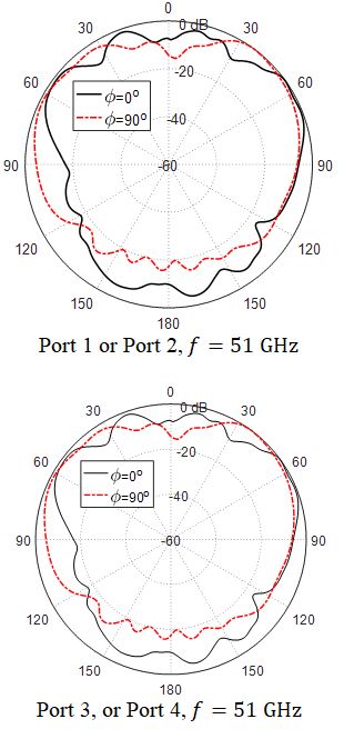
Fig. 19. Radiation patterns in the elevation planes for the quad-band MIMO antenna system at when excited at the indicated ports.
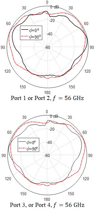
Fig. 20. Radiation patterns in the elevation planes for the quad-band MIMO antenna system at when excited at the indicated ports.
B2. Radiation patterns of the four-port MIMO antenna system
The radiation patterns produced at , , , and by the four-port MIMO antenna system, shown in Figure 14, are presented in Figures 17, 18, 19, and 20, respectively when the MIMO antenna system is excited at the different ports. The produced radiation patterns appear to be suitable for most of the future wireless applications relevant to the mobile handsets. More specifically, the radiation patterns produced at 28 and 45 GHz are ripple-free and appear to be more appropriate for long-range cellular mobile networks. On the other hand, the radiation patterns obtained at 51 and 56 GHz have some ripples and may be more appropriate for short-range communications.
IV. SUMMARY OF THE PROPOSED ANTENNA PERFORMANCE
This section is concerned with providing a summary of the most important performance metrics for the quad-band patch antenna as well as the MIMO antenna systems proposed in the present work. Table 2 gives a summary of the single-element as well as the MIMO antenna performance at the four operational frequencies. The radiation efficiency is the percentage of radiated power to the total power accepted at the antenna port. The radiated power is the accepted power minus the Ohmic losses in the conducting and dielectric parts of the antenna. The accepted power is equal to the input power minus the reflected power at the antenna port. However, the radiation efficiency listed in Table 2 is obtained by the commercially available CST studio suite® version 2017. Table 3 gives comparative performance among some mm-wave patch antennas available in some recent literature and the antenna proposed in the present work.
Table 2: Achieved frequency bands (obtained experimentally) by the proposed quad-band patch antenna and the corresponding gain and radiation efficiency
| Fc (GHz) | Fs (GHz) | Fe (GHz) | Bandwidth (GHz) | Gain (dBi) | Radiation Efficiency |
| 28 | 27.70 | 28.30 | 0.60 | 7.30 | 86.5% |
| 45 | 44.50 | 46.50 | 2.00 | 7.03 | 87.5% |
| 51 | 50.20 | 52.00 | 1.80 | 7.20 | 89.2% |
| 56 | 55.70 | 57.00 | 1.30 | 8.03 | 90.0% |
Table 3: Comparison with other published designs of mm-wave antennas
| Work | Center Frequencies (GHz) | Gain (dBi) | Patch Dimensions (mm) |
| [8] | 28, 38 | 7.2, 9.2 | |
| [16] | 28,38 | 3.7, 5.1 | |
| [1] | 38, 45 | 7.6, 7.2 | |
| [10] | 38, 54 | 6.9, 7.4 | |
| [Present] | 28, 45, 51, 56 | 7.3, 7.03, 7.2, 8.03 |
V. CONCLUSION
A novel design for a compact-size quad-band microstrip patch antenna is introduced for the 5G mobile communications in the frequency bands, , , and . The proposed quad-band antenna has primary and secondary patches which are reactively coupled and well designed to produce appropriate radiation patterns and good impedance matching in the four frequency bands of operation. Two-port and four-port MIMO antenna systems that employ the quad-band microstrip patch are investigated for operation in the 5G mobile handsets. The performance of both the quad-band patch antenna and the MIMO antenna systems are assessed including the return loss at each antenna port and the coupling coefficients between the different ports. It is shown that the simulation results agree with the experimental measurements and both show good performance. The bandwidths achieved around, , , and are, respectively, , , , and . It is shown that the ECC and the DG are perfect over the four frequency bands for the four-port MIMO antenna system.
REFERENCES
[1] K. Muhammad Irfan, A. Sohail, U. Khan, Z. Barki, and G. Witjaksono, “Elliptical slot circular patch antenna array with dual band behaviour for future 5G mobile communication networks,” Progress in Electromagnetics Research, vol. 89, pp. 133-147, 2019.
[2] Ş. Cihat, T. Ozturk, and M. Tahir Güneşer, “A single band antenna design for future millimeter wave wireless communication at 38 GHz,” European Journal of Engineering and Formal Sciences, vol. 2, no. 2, pp. 35-39, 2018.
[3] S. Jyoti and S. K. Agarwal, “Design a single band microstrip patch antenna at 60 GHz millimeter wave for 5G application,” 2017 International Conference on Computer, Communications and Electronics (Comptelix), pp. 227-230, 2017.
[4] H. Wonbin, K.-H. Baek, and S. Ko, “Millimeter-wave 5G antennas for smartphones: overview and experimental demonstration,” IEEE Transactions on Antennas and Propagation, vol. 65, no. 12, pp. 6250-6261, 2017.
[5] J. G. Andrews, S. Buzzi, W. Choi, S. V. Hanly, A. Lozano, A. C. K. Soong, and J. C. Zhang, “What will 5G be?,” IEEE Journal on Selected Areas in Communications, vol. 32, no. 6, pp. 1065-1082, 2014.
[6] A. E. Farahat and K. F. A. Hussein, “28/38 GHz dual-band Yagi-Uda antenna with corrugated radiator and enhanced reflectors for 5G MIMO antenna systems,” Progress in Electromagnetics Research C, vol. 101, pp. 159-172, 2020.
[7] W. Zamir, M. P. Abegaonkar, and S. K. Koul, “A 28-GHz antenna for 5G MIMO applications,” Progress in Electromagnetics Research, vol. 78, pp. 73-79, 2018.
[8] H. M. Marzouk, M. I. Ahmed, and A.-E. Hamied Shaalan, “Novel dual-band 28/38 GHz MIMO antennas for 5G mobile applications,” Progress in Electromagnetics Research C, vol. 93, pp. 103-117, 2019.
[9] M. H. Sharaf, A. I. Zaki, R. K., Hamad, and M. M. Omar, “A novel dual-band (38/60 GHz) patch antenna for 5G mobile handsets,” Sensors, vol. 20, no. 9, pp. 2541, 2020.
[10] D. Imran, M. M. Farooqi, M. I. Khattak, Z. Ullah, M. I. Khan, M. A. Khattak, and H. Dar, “Millimeter wave microstrip patch antenna for 5G mobile communication,” 2018 International Conference on Engineering and Emerging Technologies (ICEET), pp. 1-6, 2018.
[11] L. He-Sheng and Y.-C. Lin, “Millimeter-wave MIMO antennas with polarization and pattern diversity for 5G mobile communications: the corner design,” 2017 IEEE International Symposium on Antennas and Propagation & USNC/URSI National Radio Science Meeting, pp. 2577-2578, 2017.
[12] K. F. A. Hussein, “Fast computational algorithm for EFIE applied to arbitrarily-shaped conducting surfaces,” Progress in Electromagnetics Research, vol. 68, pp. 339-357, 2007.
[13] K. F. A. Hussein, “Efficient near-field computation for radiation and scattering from conducting surfaces of arbitrary shape,” Progress in Electromagnetics Research, vol. 69, pp. 267-285, 2007.
[14] K. F. A. Hussein, “Accurate representation of excitation and loading for arbitrarily shaped antennas composed of conducting surfaces in the method of moments,” Progress in Electromagnetics Research, vol. 36, pp. 151-171, 2012.
[15] E. M. Eldesouki, K. F. A. Hussein, and A. M. El-Nadi, “Circularly polarized arrays of cavity backed slot antennas for X-band satellite communications,” Progress in Electromagnetics Research, vol. 9, pp. 179-198, 2008.
[16] W. Ahmad and W. T. Khan, “Small form factor dual band (28/38 GHz) PIFA antenna for 5G applications,” 2017 IEEE MTT-S International Conference on Microwaves for Intelligent Mobility (ICMIM), pp. 21-24, Mar. 2017.
BIOGRAPHIES

M. Abo El-Hassan received her B.Sc., M.Sc., in Communications and Electronic Engineering, Communications Engineering from Menoufa University, Egypt, in 2007 and 2014 respectively. She received the PhD 2020. She is currently researcher at the Department of Microwave Engineering at the Electronics Research Institute.. Her current research interests include RFID, areas in Antennas, Chipless tags, SAR, Beam shaping. She has published more than 18 papers in international, regional and local scientific journals and conferences.

Asmaa E. Farahat received her B.Sc. and M.Sc. in the Department of Biomedical engineering, Faculty of Engineering, Cairo University, 2002 and 2006, respectively. She received the PhD 2012, Ain Shams University. She is currently associate professor at the Department of Microwave Engineering at the Electronics Research Institute. She has work experience in scientific research for about 17 years. She has published more than 28 papers in international, regional and local scientific journals and conferences. She has worked as secondary investigator for three research projects. Her research interests are in the areas of antennas, electromagnetic wave propagation, risk assessment of human exposure to microwave radiation, remote sensing systems, and radar systems.

Khalid F. A. Hussein received his B.Sc., M.Sc. and Ph.D. degrees in the Department of Electronics and Electrical Communications, Faculty of Engineering, Cairo University, 1990, 1995 and 2001, respectively. He is currently a professor at the Department of Microwave Engineering at the Electronics Research Institute. He has work experience in scientific research for more than 30 years. He has teaching experience in engineering colleges in many universities for more than 20 years. He has supervised more than seventy doctoral and master theses. He has published more than 100 papers in international, regional and local scientific journals and conferences. He has served as Head of Microwave Engineering Department at the Electronics Research Institute for up to four years. He has been a member of the Egyptian Space Program (currently the Egyptian Space Agency) for more than eight years. He has worked as Principal Investigator for four research projects and Head of Research Group in four other research projects. He designed and implemented several satellite antennas between prototypes and finished products. He has provided scientific consultations and conducted field measurements related to the design and distribution of mobile communication base station antennas for good signal coverage in behalf of many Egyptian and international companies. His research interests are in the areas of antennas, electromagnetic wave propagation, risk assessment of human exposure to microwave radiation, optical communications, photonics, quantum computing, radar systems, particularly ground penetrating radar (GPR), synthetic aperture radar (SAR), and remote sensing systems.
ACES JOURNAL, Vol. 36, No. 11, 1418–1428.
doi: 10.13052/2021.ACES.J.361105
© 2021 River Publishers