Novel Broadband Circularly Polarized Monopole Antenna for Multi-communication Systems
Hua Chen, Quanyuan Feng, Yan Wen, and Qiang Fu
School of Information Science and Technology
Southwest Jiaotong University, Chengdu, China
15175279665@163.com, fengquanyuan@163.com
Submitted On: May 20, 2021; Accepted On: June 21, 2021
Abstract
This paper proposes a novel coplanar waveguide (CPW) fed broadband circularly polarized (CP) monopole antenna, which applies to C-band and various wireless communication systems. The antenna consists of the double circular-shaped patch (DCSP) with square and L-shaped slots, and an improved asymmetric ground plane. The prototype of the designed antenna has been fabricated. The results of the measurement show that the 10-dB impedance bandwidth (ZBW) is 117.8% (2.2–8.5 GHz), the 3-dB axial ratio bandwidth (ARBW) is 62% (4.45–8.45 GHz).
Index Terms: Broadband, Circularly Polarized (CP), Coplanar Waveguide (CPW) Fed, Monopole Antenna.
I INTRODUCTION
In recent years, the research on the broadband and circular polarization (CP) performance of the antenna has become critical increasingly. Broadband CP antennas are gradually being utilized in various wireless communication systems due to their advantages, such as increasing the flexibility of antenna radiation directions, suppressing multipath interference, and working in multiple frequency bands at the same time [1].
A variety of low-profile, low-cost, and easy-to-manufacture CP monopole antenna structures have been proposed through researches [2–6]. These proposed structures include cutting the width of the left ground plane and introducing an L-shaped strip on the right ground [2], using the semi-circular monopole with lateral strips and its complementary structure to generate the CP mode [3], introducing a complementary L-shaped strip above the ground plane with an L-shaped slot [4], using the inclined D-shaped radiator composed of inclined I-shaped and inverted C-shaped patches [5], adding two unequal arms perpendicular to each other in the Y-shaped monopole [6]. However, the CP antennas mentioned above have narrow ARBW, which can no longer meet the multi-band requirements of current communication systems.
In order to improve the ARBW, several broadband CP monopole antennas [7–15] have been proposed. An L-shaped slot is introduced at the corresponding position of the ground with the slotted rectangular stub [7]. In [8], the inverted C-shaped monopole couples with the parasitic rectangular open-loop patch to produce CP. The inverted C-shaped monopole is coupled with the G-shaped parasitic strip, and the ground plane inserts two symmetrical square slots [9]. Adding a vertical rectangular branch above the ground with a horizontal slot to broaden the ARBW and the ZBW [10]. Two antisymmetric parasitic spiral bands are introduced to achieve CP [11]. The coupling between the moon-shaped monopole and the ground with a semi-circular slot extends the ARBW [12]. In [13], irregular trapezoidal radiation patch is used, inverted L-shaped strips and rectangular slots are introduced into the diagonal corners of the square slot grounding plane to realize a wide ZBW. In the process of in-depth research on the monopole antenna, we find that several antennas have problems with complex structures. The challenge we need to overcome is to design the CP monopole antenna with a simple structure and broadband performance.
A novel double circular-shaped monopole antenna with a simple structure is proposed in this letter. An inverted L-shaped slot is opened inside the double circular-shaped patch (DCSP) to excite a CP mode at lower frequency. Subsequently, an improved ground is introduced to widen the ZBW effectively and obtain a new CP mode at middle frequency. Finally, a square slot is etched in the upper left corner of the DCSP to change the current path of x and y directions, resulting in two orthogonal modes with equal amplitude and 90 phase difference in the upper frequency band. The broadband ZBW and ARBW of the designed antenna reach 117.8% and 62.0%, respectively. The data analysis process and design results are discussed in detail in this article.
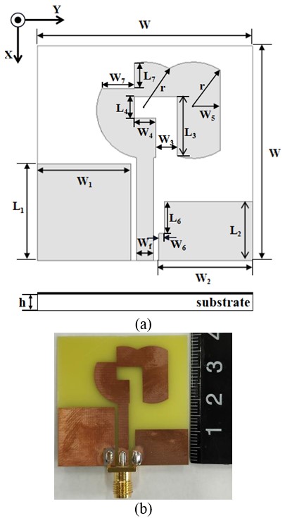
Fig. 1. (a) The geometry diagram, (b) prototype of the proposed antenna.
II ANTENNA DESIGN AND ANALYSIS
A Antenna design
The geometry diagram and prototype of the proposed broadband CP monopole antenna are shown in Figure 1. The antenna is fabricated on an FR4 (, tan = 0.02) substrate with an overall size of . The antenna is the CPW-fed structure, which is consisted of a 50 feedline, the DCSP, and an improved ground plane. The optimal sizes obtained by the software HFSS 15.0 are shown in Table 1.
Figure 2 shows five statuses of proposed antenna to better understand the design process (Ant.1–Ant.5). The simulated S11 and AR results for each model are compared in Figure 3. Ant. 1 is composed of a symmetrical ground plane and the DCSP. Compared with the traditional circular radiator, the DCSP can provide a longer current path to achieve the broadband CP bandwidth more easily while obtaining the ideal impedance matching.
Table 1: Dimensions of the proposed antenna (unit: mm)
| Parameter | Value | Parameter | Value |
| W | 40 | W8 | 2 |
| r | 9 | L9 | 4 |
| h | 0.8 | W9 | 2 |
| L | 28 | L | 11.5 |
| W | 3.2 | W | 4 |
| L | 18 | L | 4 |
| W | 17.4 | W | 4 |
| L | 11 | L | 15 |
| W | 17.4 | W | 5 |
| L | 4.8 | L | 6 |
| W | 6 | W | 1 |
| L8 | 2.5 |
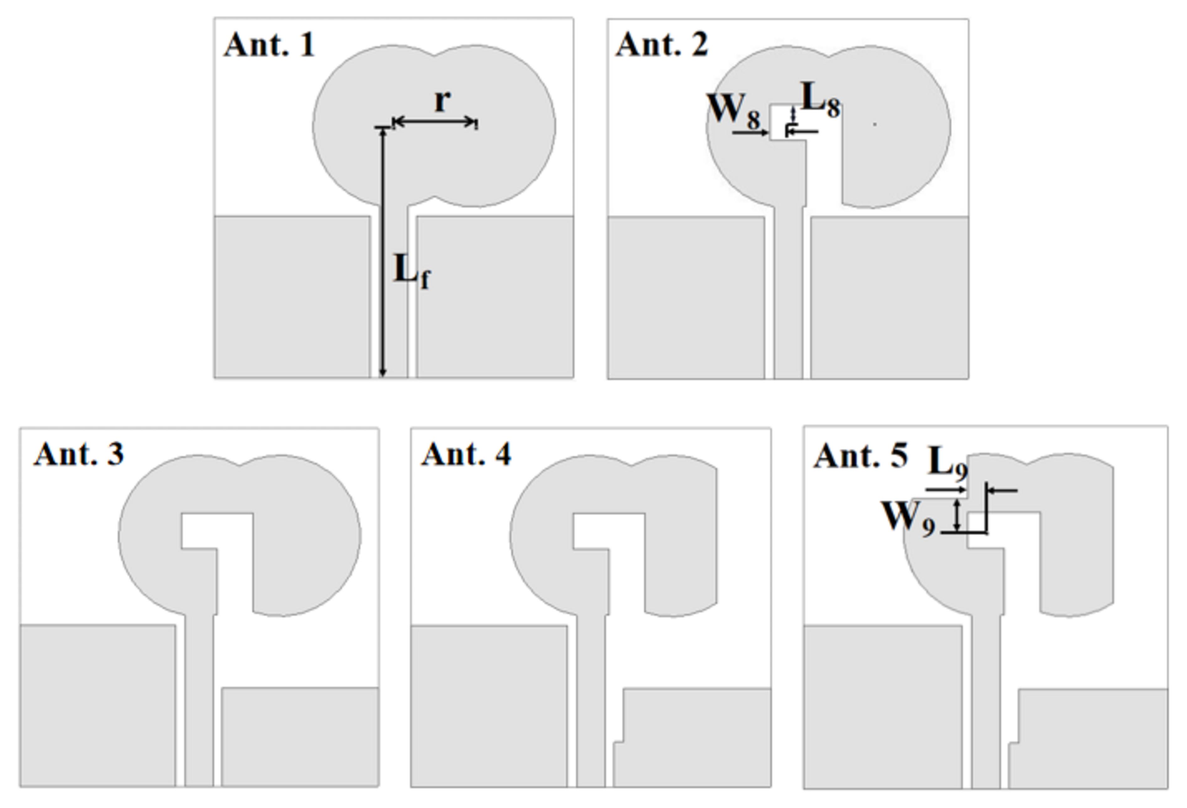
Fig. 2. Design procedures of the proposed antenna.
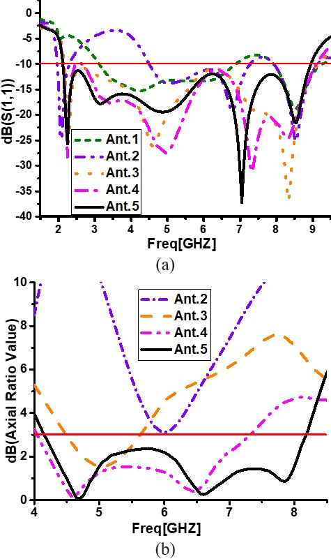
Fig. 3. Simulated results of the antenna improvement steps. (a) S11, (b) AR.
In Ant. 2, an inverted L-shaped slot is etched inside the DCSP. L-shaped slot is a common structure for CP design, which can extend the current path to obtain a new resonance frequency and excite the CP mode by orthogonal current components around the L-shaped slot. It can be seen from Figure 3 that the simulated S11 produces a new resonance frequency at 2.1 GHz, the simulated AR curve moves down and generates a basic CP mode at 6 GHz. The circumference (L) of the inverted L-shaped slot should be a quarter of the free space wavelength corresponding to the resonance frequency (f) of the S11. L is 35 mm, f is calculated to be about 2.14 GHz according to formula (1), (2). Thus, the simulated and calculated results are consistent.
| (1) |
| (2) |
where is the wavelength, c is the speed of light in free space, and f is the resonance frequency.

Fig. 4. Surface current distributions over antennas (a) Ant. 3 at 5 GHz, (b) Ant. 4 at 6.5 GHz, (c) Ant. 5 at 7.85 GHz with phases of 0, 90.
Ant. 3 improves the basic ground into an asymmetric structure. The antenna impedance matching enhances effectively in the entire frequency band, and different impedance bandwidths combine into a broadband ZBW. Simultaneously, the CP mode at 6 GHz shifts to the lower band (5 GHz) and obtains the CP bandwidth.
In Ant. 4, a rectangular slot is inserted in the upper left corner of the right ground to reduce the coupling between the feedline and ground. Thereby weakening the current intensity at the edge of the ground to balance orthogonal electric field components, and exciting a new CP mode at 6.5 GHz. By adjusting the length and width of this rectangular slot, two narrow CP modes combine into a wide ARBW. A vertical slot is cut off on the right side of the DCSP to enhance the current in the +x direction, which expands the ARBW. Finally, Ant. 5 creates a new CP mode at 7.85 GHz by etching a square slot in the upper left corner of the DCSP. Adjust W and L to change the amplitude of orthogonal currents in x and y directions around the slot. Finally, three CP modes are combined to realize the broadband CP feature, and the simulated ARBW reaches 4.15 to 8.14 GHz.
B CP mechanism analysis
To understand the CP mechanism of antenna design process, the surface current distributions of the antenna modules at 5 GHz (Ant. 3), 6.5 GHz (Ant. 4), and 7.85 GHz (Ant. 5) at 0 and 90 phases are shown in Figure 4.
The main currents are marked with dashed lines, the vector sum of the current is marked with the solid line. The currents at 180 and 360 are equal-amplitude and opposite to the currents at 0 and 90 phases, respectively. In Figure 4, the surface currents are concentrated near the edge of the ground plane, feedline, and slots of the DCSP. The parameters at these positions can be adjusted to obtain perfect CP performance.
Figure 4 (a) shows that the current vector sum of Ant. 3 at 5 GHz points to -20 and +70 relative to the +y axis at 0 and 90 phases, respectively. Two equal-amplitude orthogonal electric field components are obtained under far-field conditions, which proves that the CP mode can be achieved in this frequency band. The antenna radiates left-handed circular polarization (LHCP) in the +z direction. The same conclusions can be drawn for the current surface distributions at 6.5 GHz and 7.85 GHz in Figure 4 (b), (c). Finally, three CP modes can be obtained on the overall frequency band and combined into a broadband ARBW.
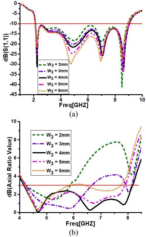
Fig. 5. Effects of W on the antenna performance. (a) S11, (b) AR.
III PARAMETRIC ANALYSIS
The antenna parameters need to be continuously analyzed and adjusted to obtain the best broadband CP performance. Figures 5, 6, and 7 illustrate the effects of varying the key parameters (L, W, and W) on the S11 and AR. In the process of parametric analysis, other parameters keep the final optimized value unchanged.
A Effects of the width of the L-shaped slot (W)
Figure 5 displays that W has a great impact on the mid-band S11 due to the coupling effect between both sides of the L-shaped slot. As W increases, the mid-band impedance matching of the antenna enhances. In addition, W also has great effects on AR bandwidth. With W increasing from 2 mm to 4 mm, the CP mode in the upper band shifts down and extends ARBW. However, CP performance deteriorates with the continued increase of W. Finally, to realize the widest ARBW, the value of W is selected as 4 mm.
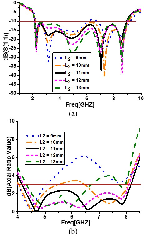
Fig. 6. Effects of L on the antenna performance. (a) S11, (b) AR.
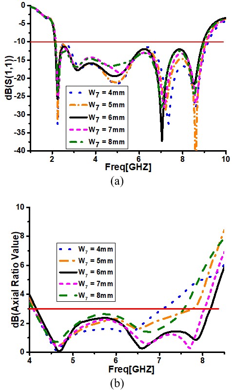
Fig. 7. Effects of W on the antenna performance. (a) S11, (b) AR.
B Effects of the height of the right ground plane (L)
It can be seen from Figure 3 that asymmetric ground plays an important role in optimizing impedance characteristics and achieving basic CP mode. Changing the height of the right ground (L) can influence current intensity at top edge of the right ground and the coupling effect between the right ground and radiator to alter the CP behavior. Figure 6 (b) exhibits that the CP modes in the middle- and high-frequency bands are sensitive to the variety of L. Through comprehensive comparison, it is determined that when the value of Lis 11 mm, the antenna gets vintage performance.

Fig. 8. Simulated and measured performance for the designed antenna. (a) S11 and (b) AR and gain.
C Effects of the width of the square slot (W)
The introduction of the square slot in the upper left corner of DCSP generates a CP mode at high frequency. W influences the y-direction current component around the slot, which strongly affects CP performance at high frequency. This effect can also be observed in Figure 7, high-frequency CP mode keeps changing with the variation of W. However, the S11 is affected slightly by W. Finally, the value of W is chosen as 6 mm.
IV EXPERIMENTAL VERIFICATION
In Figure 1 (b), the prototype has been fabricated according to optimal sizes shown in Table 1. The simulated and measured S11, AR, and gain are compared in Figures 8 (a), (b), respectively. The measured ZBW is 117.8% (2.2–8.5 GHz), and measured ARBW of the antenna is 62% (4.45–8.45 GHz), which are consistent with the simulation results, except for slight offsets in the upper and lower bands, respectively. The overall variation trend of the measured peak gain is consistent with the simulated result, but it is slightly larger than the simulation result by 1 dBic in most frequency bands and slightly lower than the simulation result above 7.4 GHz, as shown in Figure 8 (b). These differences between the measured and simulated results can be attributed to the manufacturing tolerance, the process error of welding SMA interface, and the impact of the measurement environment, but the overall measurement results are satisfactory.
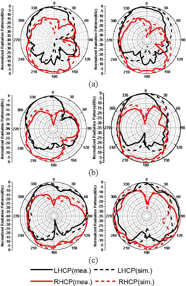
Fig. 9. Simulated and measured normalized radiation patterns at (a) 4.7, (b) 6.0, and (c) 7.5 GHz.
The normalized radiation patterns of the proposed antenna at 4.7, 6.0, and 7.5 GHz in xz (φ = 0) and yz (ϕ = 90) planes are shown in Figures 9 (a), (b), and (c), respectively. The proposed antenna radiates LHCP wave in the positive direction (+z) and RHCP wave in the opposite direction (-z) of the ground plane. The measured results agree well with simulated radiation patterns.
V CONCLUSION
A novel wideband CP monopole antenna with a simple and easily fabricated structure has been proposed in this paper. Utilizing the DCSP with an L-shaped slot and the modified asymmetric ground, broadband ARBW and ZBW is achieved. The square slot etched on the left upper of DCSP further expands ARBW. The measured ZBW of the designed antenna is 117.8%, which fully covers the ARBW of 62%. And the measured maximum peak gain is 4.6 dBic. The proposed antenna is suitable for WLAN/WiMAX/ISM (5 GHz) and C-band wireless communication systems.
ACKNOWLEDGMENT
This work was supported by 19-163-21-TS-001-062-01, and Key Project of the National Natural Science Foundation of China under Grant 62090012, 62031016, 61831017, and the Sichuan Provincial Science and Technology Important Projects under Grant 2019YFG0498, 2020YFG0282, 2020YFG0452, and 2020YFG0028.
REFERENCES
[1] U. Ullah and S. Koziel, “A broadband circularly polarized wide-slot antenna with a miniaturized footprint,” IEEE Antennas and Wireless Propagation Letters, vol. 17, no. 12, pp. 2454-2458, Dec. 2018.
[2] C. Wang and K. Hsiao, “CPW-fed monopole antenna for multiple system integration,” IEEE Transactions on Antennas and Propagation, vol. 62, no. 2, pp. 1007-1011, Feb. 2014.
[3] W. Liang, Y. Jiao, Y. Luan, and C. Tian, “A dual-band circularly polarized complementary antenna,” IEEE Antennas and Wireless Propagation Letters, vol. 14, pp. 1153-1156, 2015.
[4] S. Ahdi Rezaeieh, A. Abbosh, and M. A. Antoniades, “Compact CPW-fed planar monopole antenna with wide circular polarization bandwidth,” IEEE Antennas and Wireless Propagation Letters, vol. 12, pp. 1295-1298, 2013.
[5] A. Altaf and M. Seo, “A tilted-D-shaped monopole antenna with wide dual-band dual-sense circular polarization,” IEEE Antennas and Wireless Propagation Letters, vol. 17, no. 12, pp. 2464-2468, Dec. 2018.
[6] A. Ghobadi and M. Dehmollaian, “A printed circularly polarized Y-shaped monopole antenna,” IEEE Antennas and Wireless Propagation Letters, vol. 11, pp. 22-25, 2012.
[7] K. O. Gyasi, G. Wen, D. Inserra, Y. Huang, J. Li, A. E. Ampoma, and H. Zhang, “A compact broadband cross-shaped circularly polarized planar monopole antenna with a ground plane extension,” IEEE Antennas and Wireless Propagation Letters, vol. 17, no. 2, pp. 335-338, Feb. 2018.
[8] K. Ding, C. Gao, T. Yu, and D. Qu, “Broadband C-shaped circularly polarized monopole antenna,” IEEE Transactions on Antennas and Propagation, vol. 63, no. 2, pp. 785-790, Feb. 2015.
[9] M. Midya, S. Bhattacharjee, and M. Mitra, “Broadband circularly polarized planar monopole antenna with G-shaped parasitic strip,” IEEE Antennas and Wireless Propagation Letters, vol. 18, no. 4, pp. 581-585, Apr. 2019.
[10] L. Zhang, Y. Jiao, Y. Ding, B. Chen, and Z. Weng, “CPW-fed broadband circularly polarized planar monopole antenna with improved ground-plane structure,” IEEE Transactions on Antennas and Propagation, vol. 61, no. 9, pp. 4824-4828, Sep. 2013.
[11] K. Ding, C. Gao, Y. Wu, D. Qu, and B. Zhang, “A broadband circularly polarized printed monopole antenna with parasitic strips,” IEEE Antennas and Wireless Propagation Letters, vol. 16, pp. 2509-2512, Jul. 2017.
[12] B. Hu, Nasimuddin, and Z. Shen, “Broadband circularly polarized moon-shaped monopole antenna,” Microwave and Optical Technology Letters, vol. 57, no. 5, pp. 1135–1139, May 2015.
[13] M. Shokri, S. Asiaban, and Z. Amiri, “Study, design and fabrication of a CPW fed compact monopole antenna with circular polarization for ultra wide band systems application,” Applied Computational Electromagnetics Society (ACES) Journal, vol. 32, no. 9, pp. 749-753, Sep. 2017.
[14] F. Azamian, Fateme, M. N. Azarmanesh, and C. Ghobadi, “A novel compact CPW-fed antenna with circular polarization characteristics for UWB applications,” Applied Computational Electromagnetics Society (ACES) Journal, vol. 30, no. 1, pp. 93-98, Jan. 2015.
[15] B. Xiao, L. Zhong, J. S. Hong, and S. L. Li, “A novel compact planar spiral-shaped antenna,” Applied Computational Electromagnetics Society (ACES) Journal, vol. 28, no. 1, pp. 57-63, Jan. 2013.
BIOGRAPHIES

Hua Chen was born in Baoding, Hebei, China, in 1997. She is currently working toward her Master’s degree in Electronic and Communication Engineering at Southwest Jiaotong University, Chengdu, China. Ms, Chen’s main research content is antenna design and theory, mainly in circularly polarization antennas.

Quanyuan Feng (M’06–SM’08) received his M.S. degree in microelectronics and solid electronics from the University of Electronic Science and Technology of China, Chengdu, China, in 1991, and Ph.D. degree in EM field and microwave technology from Southwest Jiaotong University, Chengdu, China, in 2000. He is the Head of Institute of Microelectronics, Southwest Jiaotong University, Chengdu, China. Mr. Feng has been honored as the “Excellent Expert” and the “Leader of Science and Technology” of Sichuan Province owing to his outstanding contributions. In the recent 5 years, more than 500 of his papers have been published on IEEE Transactions on Antennas and Propagation, IEEE Transactions on Microwave Theory and Techniques, IEEE Antennas and Wireless Propagation Letters, etc., among which more than 300 were registered by SCI and EI. His research interests include integrated circuits design, RFID technology, embedded system, wireless communications, antennas and propagation, microwave & millimeter wave technology, smart information processing, electromagnetic compatibility, RF/microwave devices and materials, etc.

Yan Wen received the B.S. degree in Transportation from Southwest Jiaotong University, Chengdu, China, and is currently working in Southwest Jiaotong University. Herresearch interests include circuit design and antennas.

Qiang Fu (1997) received his B.E. degree from Nanchang Hangkong University, Nanchang, China, in 2019. He is currently pursuing M.Eng degree with the School of Information and Communication Engineering, Southwest Jiaotong University, Chengdu, China. Mr. Fu’s current research interests include circularly polarized antennas, and wideband antennas.
ACES JOURNAL, Vol. 36, No. 10, 1312–1318.
doi: 10.13052/2021.ACES.J.361007
© 2021 River Publishers