Pattern Analysis of Conformal Antenna Arrays via the Characteristic Modes of Isolated Elements
Yuanchen Zeng, Shuo Zhang, and Shunxi Lou
Key Laboratory of Electronic Equipment Structure Design of Ministry of Education
Xidian University, Xi’an, Shaanxi 710071, China
zengyuanchen123@qq.com, 18392027103@163.com, sxlou_xd@126.com
Submitted On: September 4, 2021; Accepted On: December 19, 2021
Abstract
A simple pattern analysis method is presented for conformal antenna arrays, considering mutual coupling effects based on the characteristic modes of isolated elements. There are many methods to analyze the performance of conformal antenna arrays, but they seldom provide a clear insight into the coupling mechanism. Thus, the overall characteristic modes of the conformal array are calculated from the characteristic modes of the isolated elements and coordinate transformation, which are different from the traditional modal analysis for the entire array. And the radiation field of the conformal array is given. The modal coupling matrix which depends on the structural parameters and relative pose of conformal elements is used to characterize the mutual coupling effect between elements and explain the coupling mechanism from the perspective of the characteristic currents. Finally, the effectiveness and efficiency of the proposed method is verified by some numerical examples.
Index Terms: conformal array, characteristic modes, coordinate transformation, mutual coupling.
I. INTRODUCTION
Conformal antennas have been widely used in radio communications and avionics due to their remarkable electrical performance [1, 2]. Although a wealth of research has been conducted on the analysis of the electromagnetic characteristics of conformal antennas, they rarely provide a clear insight into the coupling mechanism. The simple and intuitive understanding of the mutual coupling mechanism of the conformal array antenna is helpful for further research on its radiation performance [1].
State-of-the-art conformal array analysis methods fall under two main categories. The first one includes use of an approximate method that can serve as a reference for the pattern analysis of the conformal array. The simplest technique is to apply coordinate transformation into the classical pattern theory [3]. But it can only be applied in the absence of mutual coupling effects. The diffraction ray solution based on the uniform geometrical theory of diffraction (UTD) is often used to analyze conformal arrays on the surface of typical geometric models [1, 4]. UTD can analyze the pattern of conformal antenna arrays including mutual coupling, as a high-frequency approximation method, but it has higher requirements for antenna operating frequency. The higher the frequency is, the more accurate the result is. In addition, there are special analysis methods for conformal antennas, such as cavity model analysis which is discussed in detail. The microstrip antenna is equivalent to a 22 dipole array. The relative pose of dipoles is optimized to simplify pattern analysis of the conformal antenna [5]. The other strategy includes an accurate analysis method that can help achieve the pattern analysis according to the electromagnetic field control equation and boundary conditions, for example, the method of moments (MoM) is used to model the conformal array as a whole system and analyze its radiation performance [6].
However, the methods mentioned above do not show a clear insight into the coupling mechanism. Thus, an analysis method to explore the coupling relationship between radiating elements has been developed. For example, domain decomposition method combined with generalized scattering matrix (GSM) is used to analyze the conformal antennas performance on aircraft [7]. Although the overall generalized scattering matrix of an array constructed by the GSM of an isolated radiating element can accurately characterize the electromagnetic field of the array, it requires that the minimum spheres surrounding each radiating element do not overlap [8]. Further analysis is needed if the minimum spheres overlap [9, 10], which increases the difficulty of using this method in conformal arrays. And the coupling matrix given in GSM can only represent the position relationship of elements. That is, the coupling mechanism is mathematically perfect, but its physical insight is still unclear. A method of sampling the far-field data of an isolated element to analyze the mutual interactions between the array elements in the far-field region is mentioned [11]; it does not present a clear physical insight into the coupling mechanismeither.
The theory of characteristic modes has been widely used in antenna analysis and design lately, providing a physical explanation for the antenna radiation mechanism [12, 13, 14]. However, these applications treat the array or antenna as a multiport network and analyze the entire array or antenna. Then we do a research on the characteristic modes of a planar array; the correlation model between the electrical performance parameters of an entire array and the characteristic modes of isolated radiating elements is established [15]. On the basis of this solution strategy and coordinate transformation, this paper analyzes the overall characteristic modes of conformal arrays and describes the coupling mechanism from the perspective of the characteristic currents clearly.
This paper is organized as follows. First, the radiation pattern and modal coupling matrix of conformal antenna arrays are analyzed based on the characteristic modes of an isolated conformal element and coordinate transformation. Second, the proposed method is verified by some numerical experiments. Finally, some meaning conclusions are given.
II. THEORY
A. Process of the proposed method
Figure 1 shows the flow chart of the application of the proposed method to the analysis of conformal arrays. The process is as follows.
Firstly, the characteristic modes of the isolated radiating element are analyzed using the MoM. Secondly, the modal coupling matrix is constructed based on the modal current and coordinate transformation. On this basis, the modal excitation matrix is constructed, and then the modes are superimposed to obtain the radiation field of the conformal array.
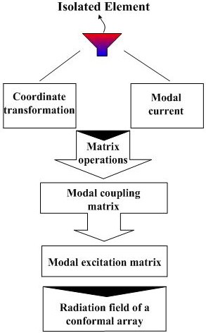
Figure 1: Process of the proposed method.
B. Modal excitation matrix of a conformal array
Considering a conformal array on an arbitrary surface in the coordinate system shown in Figure 2 (a), refer to the planar array [15], under the influence of other elements, the incident field of the nth element can be expressed as
| (1) |
where is the incident field of the nth isolated element. is the scattered field from other elements in the corresponding local coordinate system. defines the number of elements. And which requires three Euler rotations is the rotation matrix of the th element relative to the nth element. Rotate aroundby, respectively. The three angles are the rotation angles of the outside normal vector of the th element relative to the nth element, as shown in Figure 2 (b). The coordinate transformation process can be expressed as [16]
| (2) |
where
| (3) |
| (4) |
| (5) |
Refer to [15], the modal excitation coefficient of th mode for the nth element in a conformal array environment can be written as
| (6) |
where is the characteristic current of th mode for the nth element.
The scattered field of the th element is [15]
| (7) |
where are the modal excitation coefficient, characteristic field and eigenvalue of th mode for the kth element, respectively. represents the number of modes for the kth element.
Substituting eqn (7) into (6), the modal excitation coefficient of th mode for the nth element in an array environment is composed of two parts: the initial modal excitation coefficient of the isolated element and the modal excitation coefficient affected by other elements, which can be further expressed as
| (8) |
wherein
| (9) |
| (10) |
where is the initial modal excitation coefficient of th mode for the nth element, and is the modal coupling coefficient between the elements.
Further, eqn (9) and (10) can be written as
| (11) |
| (12) |
where is the delta-gap voltage at the feeding port of the nth element. is the modal electric current at feeding port of th mode for the nth element, details shown in [17]. represents an operator that converts into [18] which has the dimension of impedance. is the characteristic current of th mode for the kth element. Eqn (10) shows the mutual coupling is related to the characteristic current.
Extending eqn (8) to the conformal array, we can get
| (13) |
where and are respectively given by the following matrix.
| (14) |
| (15) |
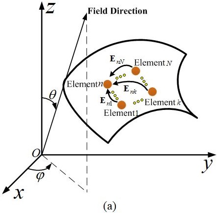
Figure 2: Mutual coupling of conformal elements, (a) conformal array on an arbitrary surface, (b) position relationship of two elements.
| (16) |
| (17) |
and
| (18) |
| (19) |
| (20) |
| (21) |
where represents the number of modes for the nth element.
In practical applications, the number of modes cannot be infinite, so the empirical truncation rule is given by [15]
| (22) |
where is the number of modes with the modal significance not less than , and a positive integer depends on the required accuracy of the solution.
Further solving the implicit equation (13), the modal excitation matrix of the array can be obtained
| (23) |
where is the identity matrix.
C. Radiation field of a conformal array
Thus, the radiation field of the conformal array on arbitrary curved surface at is
| (24) |
where
| (25) |
and
| (26) |
herein is the free-space wave number. is the position vector. is the unit vector of the observation direction. is the characteristic field of th mode for the nth element. represents the transformation matrix between the local coordinate system and the global coordinate system , which can be expressed as
| (27) |
where the definition of is similar to eqn (3), (4) and (5). are the angles between and respectively, as shown in Figure 2 (b).
III. NUMERICAL RESULTS AND VALIDATION
This section presents two numerical examples to verify the effectiveness of the proposed method. The numerical results are compared with those of the MoM [19] and the finite element method (FEM) [20].
A. Example 1
The structure of the element with the feed amplitude of 1 V and the phase of 0 degree is shown in Figure 3. A symmetrical 55 antenna array conformal on a parabolic cylinder at 2 GHz with a spacing of between elements was analyzed, as shown in Figure 4 (a). is the wavelength and the number of modes is . The circumferential curve equation is
| (28) |
where the variable unit is and .
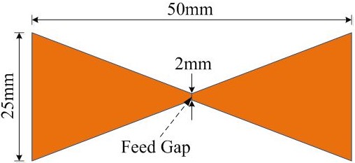
Figure 3: Geometry and dimensions of the bowtie antenna before conformed to the surface [15].
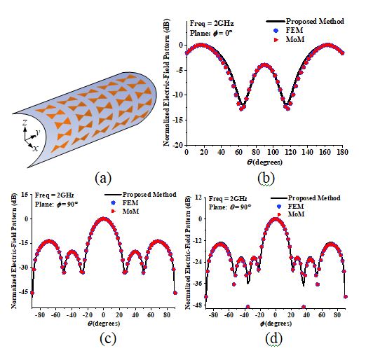
Figure 4: Parabolic conformal array and normalized electric-field pattern, (a) parabolic cylindrical conformal array, (b) cut, (c) cut, (d) cut.
The parabolic cylinder has different circumferential curvatures, so conformal radiating elements are not identical in the circumferential direction. Considering the symmetry of the 55 array, three types of Rao–Wilton–Glisson (RWG) basis function need to be processed, and then extended to axial elements through rotation and translation.
Figure 4 (b), (c) and (d) show the normalized electric-field pattern analysis results of a 55 conformal array calculated by the proposed method, FEM and MoM considering mutual coupling effects at planes , and . Observing the pattern of the three main planes, we found that the results analyzed by the proposed method are basically the same as those of FEM and MoM. This demonstrates the effectiveness of the proposed method in multiple conformal elements of different curvatures.
To further verify the effectiveness of the proposed method, the array shown in Figure 4 (a) is still used and only the element spacing is changed. Table 1 shows the errors of radiation fields obtained by the proposed method, FEM and MoM. The error [15] of radiation fields were calculated by
| (29) |
where is the number of sample points in three main cuts. and are the electric field values obtained by the proposed and existing methods, respectively. and are the maximum values of and , respectively.
Table 1: The errors of radiation fields obtained by different methods
| Spacing | (%) | (%) |
|---|---|---|
| 0.5 | 1.46 | 1.42 |
| 0.6 | 2.15 | 2.17 |
| 0.7 | 1.83 | 1.79 |
| 0.8 | 2.31 | 2.19 |
In order to validate the efficiency of the proposed method, according to Figure 1, the proposed method is divided into three steps in general. Firstly, the generalized characteristic equation is solved to obtain the modal current of the isolated radiating element by the implicitly restarted Arnoldi method [21, 22]. The number of basis functions is set as , and the time complexity of this step is . Secondly, the modal coupling matrix is constructed to derive the modal excitation matrix, and the time complexity of this step is . Finally, the superposition principle is used to obtain the radiation field of the entire conformal array, and its time complexity is . Therefore, when the number of array elements is , , the time complexity of the entire algorithm is . The time complexity is for the classical MoM. So, the proposed method is more efficient than the method of moments for electrically small-sized radiating elements ().
The following takes the calculation time of different sizes of array composed of bowtie antenna shown in Figure 3 as an example to illustrate the efficiency of the proposed method, as shown in Table 2.
Table 2: Computation cost for the conformal arrays (CPU: i5-6500 3.20 GHz, RAM:8.00 GB)
| Size | Number of RWG | CPU Time with FEKO (sec.) | CPU Time with the proposed method (sec.) |
|---|---|---|---|
| 99 | 1863 | 8.42 | 0.46 |
| 1515 | 5175 | 63.77 | 4.94 |
| 2121 | 10143 | 270.30 | 21.25 |
| 2727 | 16767 | 815.44 | 97.90 |
B. Example 2
The ground effect is not considered in the above example. So, we consider a more complex array. The coaxially fed microstrip antenna is used as conformal array elements, as shown in Figure 5 (a). The feed amplitude is 1 V, and the phase is 0; the array element works at 2.4 GHz. The geometrical parameters of a microstrip antenna are consistent with those of [5].
An equivalent method of a microstrip antenna is proposed in [5] on the basis of the cavity model method. The microstrip antenna can be equivalent to the 22 electric dipoles on the ground of a perfect electrical conductor, as shown in Figure 5 (b) and (c).
It’s noted that the dipole in the equivalent model adopts a strip dipole with a width of 2 mm to apply the proposed method, which is different from [5]. The optimized parameters of the equivalent model for a microstrip antenna are shown in Table 3. The root-mean-square error of normalized electric-field pattern for the abovementioned equivalent model is 0.45%. And the normalized near-field distribution of the microstrip patch antenna and its equivalent model are shown in Figure 6.
Table 3: Optimized parameters of the equivalent model for the microstrip antenna
| (mm) | (mm) | () |
|---|---|---|
| 31.31 | 35.66 | 14.86 |
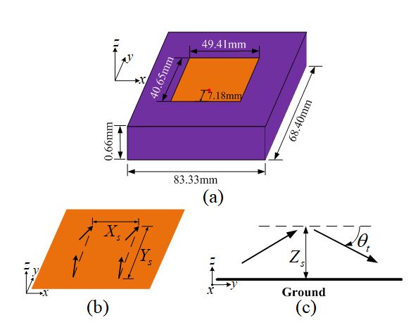
Figure 5: A microstrip antenna and its equivalent model, (a) the microstrip antenna, (b) its equivalent 22 dipole array model, (c) side view of the equivalent model.
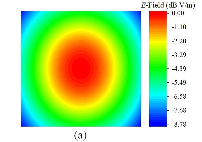
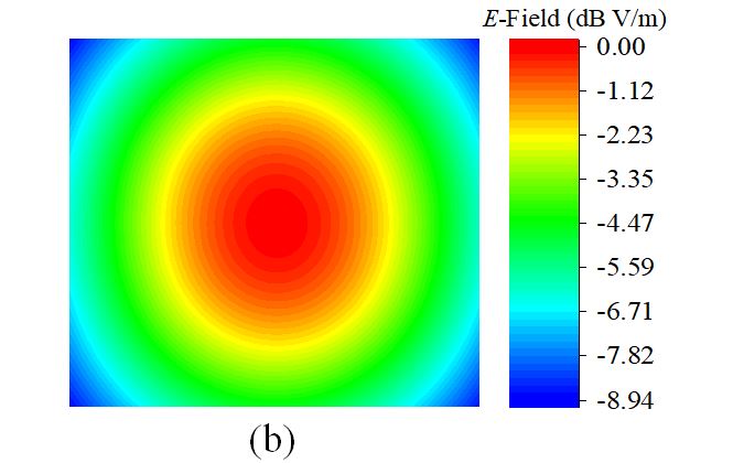
Figure 6: The normalized near-field distribution, (a) the microstrip antenna, (b) its equivalent 22 dipole array model.
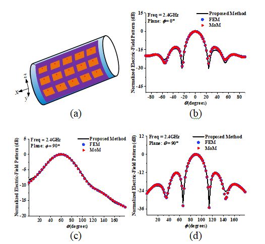
Figure 7: Microstrip conformal array and normalized electric-field pattern, (a) cylindrical conformal array, (b) cut, (c) cut, (d) cut.
A 35 microstrip antenna array is conformal on a cylinder with a radius of 83.33 mm, as shown in Figure 7 (a). The element spacing is . Then, we feed the 22 equivalent model with the uniform amplitude and the number of modes is . It is clear that the results calculated by the proposed method, MoM and FEM are consistent on the three main planes from Figure 7 (b), (c) and (d), which shows the effectiveness of the proposed method. The abovementioned model has a certain deviation in the region that is far from the main lobe. This occurs owing to the error caused by the equivalent model of the microstrip antenna.
IV. CONCLUSION
This paper presents a method for analyzing the performances of conformal array antennas based on the characteristic modes of isolated elements. Combining the coordinate transformation, the modal coupling matrix is constructed to derive the field formula of the conformal array. The modal coupling matrix is only related to the structural parameters of the elements and relative pose, and presents a clear physical insight into the coupling mechanism of conformal radiating elements from the perspective of the characteristic currents. Finally, some examples are used to validate the proposed method. This provides a basis for further research on the conformal array.
ACKNOWLEDGMENT
The paper is supported by the Fundamental Research Funds for the Central Universities and the Innovation Fund of Xidian University (Grant No. U1931139).
REFERENCES
[1] L. Josefsson, Conformal Array Antenna Theory And Design, Hoboken, NJ, USA: Wiley, 2006.
[2] Y. Li, “Synthesis of conical conformal array antenna using invasive weed optimization method,” Applied Computational Electromagnetics Society (ACES) Journal, vol. 28, no. 11, pp. 1025-1030, Nov. 2013.
[3] H. M. Bernety, S. Venkatesh, and D. Schurig, “Analytical phasing of arbitrarily oriented arrays using a fast, analytical far-field calculation method,” IEEE Trans. Antennas Propagat., vol. 66, no. 6, pp. 2911-2922, Jun. 2018.
[4] P. H. Pathak, “A collective UTD ray analysis for the radiation from conformal linear phased array antennas on large cylindrical surfaces,” In EUCAP, Paris, France, 2017.
[5] S. P. Gao, “Installed radiation pattern of patch antennas: prediction based on a novel equivalent model,” IEEE Trans. Antennas Propagat Mag., vol. 57, no. 3, pp. 81-94, Jun. 2015.
[6] W. J. Zhao, “Analysis of radiation characteristics of conformal microstrip arrays using adaptive Integral Method,” IEEE Trans. Antennas Propagat., vol. 60, no. 2, pp. 1176-1181, Feb. 2012.
[7] B. Andr and P. Caudrillier, “Domain decomposition method based on Generalized Scattering Matrix for installed performance of antennas on aircraft,” IEEE Trans. Antennas Propagat., vol. 55, no. 6, pp. 1833-1842, Jun. 2007.
[8] J. Rubio, “Array thinning of coupled antennas based on the orthogonal matching pursuit method and a spherical-wave expansion for far-field synthesis,” IEEE Trans. Antennas Propagat., vol. 63, no. 12, pp. 5425-5432, Dec. 2015.
[9] J. F. Izquierdo, “Efficient radiation antenna modeling via orthogonal matching pursuit in terms of infinitesimal dipoles,” IEEE Antennas Wireless Propagat Lett., vol. 15, pp. 444-447, 2015.
[10] J. Rubio, “Mutual coupling of antennas with overlapping minimum spheres based on the transformation between spherical and plane vector waves,” IEEE Trans. Antennas Propagat., vol. 69, no. 4, pp. 2103-2111, Apr. 2021.
[11] T. Marinovic, “Fast characterization of mutually-coupled array antennas using isolated antenna far-field data,” IEEE Trans. Antennas Propagat., vol. 69, no. 1, pp. 206-218, Jan. 2021.
[12] Z. Ma and Q. Wu, “Reduction of mutual coupling for broadband vivaldi antennas using characteristic modes analysis and lumped loads,” Applied Computational Electromagnetics Society (ACES) Journal, vol. 34, no. 6, pp. 921-926, Jun. 2019.
[13] A. Nikfal, G. Dadashzadeh, and M. Naser-Moghadasi, “A reconfigurable crossed dipole antenna for polarization diversity using characteristic mode theory,” Applied Computational Electromagnetics Society (ACES) Journal, vol. 34, no. 9, pp. 1320-1326, Sep. 2019.
[14] L. Ling, “Efficient characteristic mode analysis for radiation problems of antenna arrays,” IEEE Trans. Antennas Propagat., vol. 67, no. 1, pp. 199-206, Jan. 2019.
[15] S. X. Lou, “Analysis of finite antenna arrays using the characteristic modes of isolated radiating elements,” IEEE Trans. Antennas Propagat., vol. 67, no. 3, pp. 1582-1589, Mar. 2019.
[16] T. Milligan, “More application of Euler rotation angles,” IEEE Trans. Antennas Propagat Mag., vo1. 41, no. 4, pp.78-83, Aug. 1999.
[17] Q. Wu and W. Su, “Reduction of out-of-band antenna coupling using characteristic mode analysis,” IEEE Trans. Antennas Propagat., vol. 64, no. 7, pp. 2732-2742, Jul. 2016.
[18] S. D. Rao, “Electromagnetic scattering by surfaces of arbitrary shape,” IEEE Trans. Antennas Propagat., vol. 30, no. 3, pp. 409-418, May. 1982.
[19] S. N. Makarov, Antenna and EM modeling with Matlab. New York, 2002.
[20] J. M. Jin, The Finite Element Method in Electromagnetics. New York: Wiley, 2002.
[21] Y. Chen and C. F. Wang, Characteristic Modes: Theory and Applications in Antenna Engineering. Hoboken, NJ, USA: Wiley, 2015.
[22] R. B. Lehoucp, D. C. Sorensen, and C. Yang, ARPACK Users Guide: Solution of Large-Scale Eigenvalue Problems with Imlicitly Restarted Arnoldi Methods. Philadelphia, PA: SIAM, 1998.
BIOGRAPHIES

Yuanchen Zeng was born in Shaanxi, China, in 1996. He received the B.S. degree in mechanical design manufacture and automation major from Xidian University, Xi’an, China, in 2017, where he is currently pursuing the Ph.D. degree in electromechanical engineering. His current research interests include conformal arrays and computational electromagnetics.

Shuo Zhang was born in Heilongjiang, China, in 1993. She received the B.S. degree in automation technology from Xidian University, Xi’an, China, in 2016, where she is currently pursuing the Ph.D. degree in electromechanical engineering. Her current research interests include the theory of microwave power transmission, antenna arrays, and aperture antennas.

Shunxi Lou was born in Hebei, China, in 1992. He received the B.S. and Ph.D. degrees from Xidian University, Xi’an, China, in 2015, and 2021, respectively. His current research interests include the theory of characteristic modes, antenna arrays, and computational electromagnetics.
ACES JOURNAL, Vol. 36, No. 12, 1562–1568.
doi: 10.13052/2021.ACES.J.361207
© 2021 River Publishers