Computational Analysis for Miniaturization of Tapered Slot Antenna using Elliptical Conducting Loaded Strips
Bismah Tariq, Muhammad Amjad, and Abdul Aziz
Faculty of Engineering, The Islamia University of Bahawalpur, Pakistan
bismah.tariq91@gmail.com, muhammd.amjad@iub.edu.pk, abdul.aziz@iub.edu.pk
Submitted On: September 14, 2021; Accepted On: August 2, 2022
Abstract
In this paper, the computational analysis for miniaturization of antipodal Vivaldi antenna (AVA) by an additional single elliptical loaded strip (SELS) is presented. The performance of the miniaturized antenna is evaluated by finite difference time domain (FDTD) technique, while its performance is also verified by finite element method (FEM). The computational time and cost of the two techniques are also compared to highlight the significance of the most suitable technique for miniaturization of the wideband antenna. It achieves ultra-wideband performance with lower cutoff frequency at 0.668 GHz and 19.52 size reduction with suitable gain performance. The proposed compact antenna exhibits good performance in the sub-GHz and ultra-wideband (UWB) frequency ranges, which makes it a suitable candidate for low power energy harvesting systems as well as for ultra-wideband applications.
Index Terms: Antipodal Vivaldi antenna (AVA), compact, energy harvesting, sub-GHz, tapered slot antenna (TSA), ultra-wideband (UWB) applications, Vivaldiantenna.
I. INTRODUCTION
Wireless remote-controlled systems for Internet of Things (IoT) are always appealing to everyone as they add ease to daily mankind’s routine and also help in multi-tasking. IoT typically requires a wider frequency range, which can be provided by ultra-wideband antennas with extended ranges to sub-GHz frequency ranges. It has the benefit of extended frequency range and lower power consumption. Thus it is suitable for networking where a small amount of data is to be transmitted periodically such as in IoT networking [1], Chaos-based communication systems [2], RFID tagging, air quality network sensor devices [3], wireless drones and microphones. Therefore, an antenna that can cater to the high-frequency region as well as the sub-GHz band efficiently seems attractive for energy harvesting systems in low energy application systems.
Antipodal Vivaldi antenna (AVA) is one such family of antennas, which has promising potential to meet the need of the hour due its wide bandwidth, high directivity, better radiation efficiency and stable radiation pattern properties. This is the reason why AVA attracts the attention of researchers nowadays for energy harvesting applications [4, 5]. Efforts are being made to improve its performance and reduce the size of conventional Vivaldi antenna [6] and antipodal Vivaldi antenna [7] particularly for the sub-GHz frequency band. However, there is still need to improve its compactness for sub-GHz frequency ranges to make it more suitable candidate for energy harvesting applications.
Different flare shapes and tapering techniques [8, 9] nowadays are being practiced and proposed for the size reduction and performance enhancement of AVA. Printing of meta-material unit cells on either side of the substrate is helpful for improving gain and reducing antenna size and sidelobe levels [10, 11]. The gain performance of the antenna can also be improved by substrate integrated waveguide (SIW) structure [12] and the corrugation technique [13, 14], however, it increases the complexity level of fabrication. The resistance loading and slotting technique can also be helpful for antenna miniaturization and gain enhancement [15, 16]. However, most of these techniques are complex and size reduction of an AVA for sub-GHz applications is still challenging. Moreover, the computational time and cost for analysis of such wideband antennas make the task more difficult.
This paper presents a modified AVA design that uses the simple technique of loading elliptical shaped conducting strips for reducing the antenna size with comparable radiation and gain performance in the sub-GHz range without affecting its performance at higher frequencies. As the proposed technique affects only lower frequencies performance, so parametric analysis computational cost can be reduced significantly by limiting the analysis to lower frequencies only. Section 2 discusses the antenna configuration and design, section 3 presents all the results and discussion and section 4 presents conclusions of the study.
II. ANTENNA DESIGN
A conventional AVA (CAVA) proposed in [8], is selected for its size reduction.
Initial aperture size of a CAVA is an important parameter to decide its lower cutoff frequency through an empirical relation given as [8]:
| (1) |
In eqn (1), is the velocity of light in free space and is the relative permittivity of the dielectric substrate. The significance of the aperture size comes from the fact that, if it is less than the value obtained from eqn (1) then it affects negatively the broadband characteristics of the antenna [16]. The general expression for determination of the shape contour of a Vivaldi antenna is quoted as eqn (2):
| (2) |
While for better impedance characteristics, the slot is typically exponentially tapered [16] as per the eqn (3):
| (3) |
In eqn (3), is the width of the feeding microstrip and is the exponential rate of transition and is determined by the eqn (4):
| (4) |
where is the effective radiation length.
All the design parameters for CAVA are summarized in Table 1. All the dimensions are measured in millimeters.
Table 1: Antenna design parameters
| Parameter | Value | Parameter | Value |
|---|---|---|---|
| CAVA | |||
| 161.25 | 2.975 | ||
| 140 | 60 | ||
| 32.5 | 10 | ||
| 42.25 | 70 | ||
| 43.2 | 33.5 | ||
| 27 | 72.75 | ||
| 132 | 33.5 | ||
| 67 | 115 | ||
| 8 | 10 | ||
| 60 | 5.95 | ||
| 7.5 | 42.5 | ||
| 4.65 | 12.75 | ||
| SELS-AVA | |||
| 15 | 33.5 | ||
| 37 | 45 | ||
The CAVA has a lower cutoff frequency of 0.83 GHz. Its size is 0.446 x 0.387 , where is the wavelength in free space at the lowest cutoff frequency.
The surface current distribution analysis for CAVA played important role to modify its structure to shift lower cutoff frequency towards left without changing its aperture size. The surface current distributions for CAVA at 0.69 GHz and 2.5 GHz are illustrated in Fig. 1. It can be seen that the surface current density is accumulated at the lower curves of the radiating flares as well as around the slot between the two flares at 0.69 GHz. However, the surface current distribution at 2.5 GHz and higher frequencies is focused only around the slot between the two flares and no significant current can be seen at the lower curves of both the flares. It shows that lower curves of both the flares have a significant role to decide the lower cutoff frequency of CAVA. So, any possible way to increase the electrical path of the current along the lower curve of the flare may help to shift the lower cutoff frequency of CAVA towards the left without any increase in its aperture size.
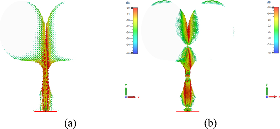
Figure 1: The surface current distribution of CAVA at (a) 0.69 GHz and (b) 2.5 GHz.
A. Modified CAVA configuration
An elliptical conducting strip is loaded on lower curves of both the flares of CAVA to shift its lower cutoff frequency towards the left. As the strips are loaded to the lower curves of the flares of CAVA at which it has appreciable current density for low frequencies. Therefore, it helps to increase the electrical length of the antenna at low frequencies. The modified CAVA is named SELS-AVA and is presented in Fig. 2.
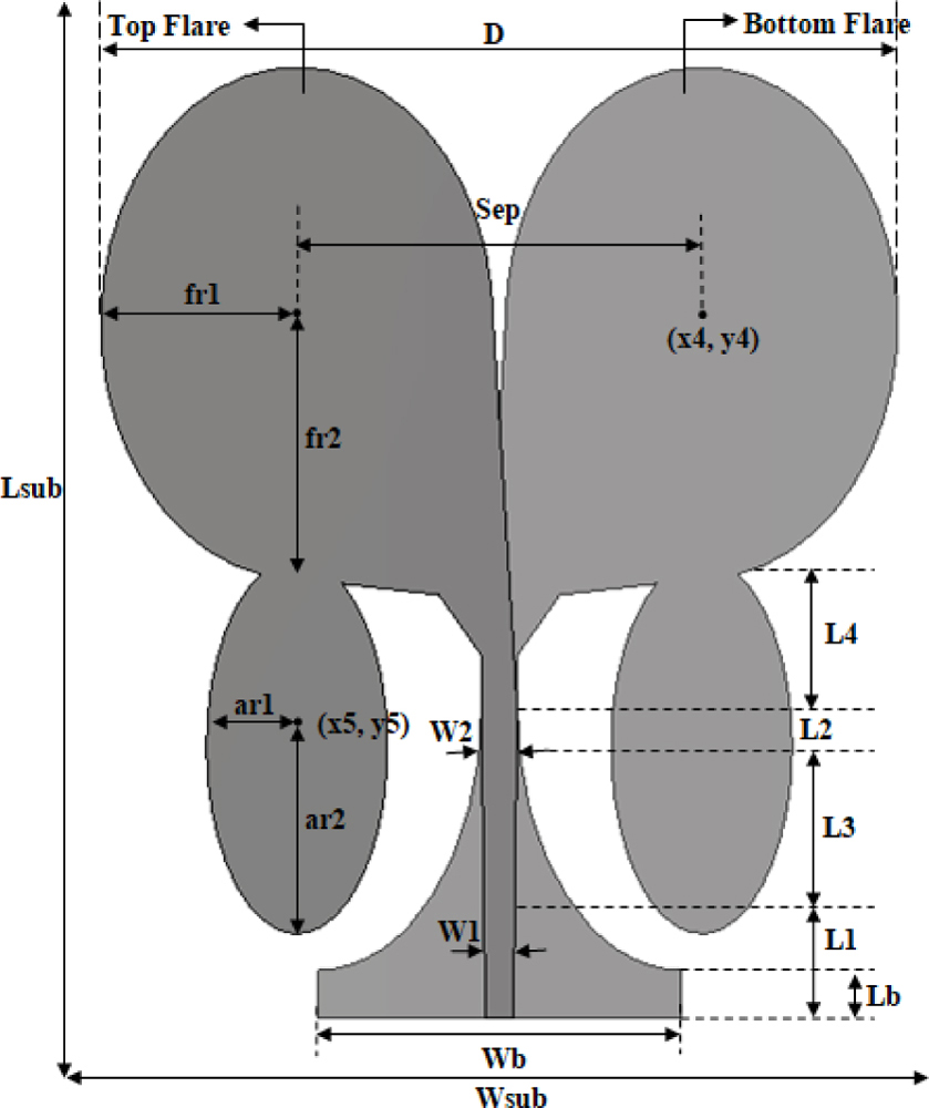
Figure 2: Schematic of the SELS-AVA design.
While loading the CAVA with additional strips, the antenna symmetry is kept intact. The center of the loaded strip is (, ) and its major and minor axes are and , respectively. Both the strips are the mirror image of one another, just like the radiating flares of CAVA.
The added strips are chosen to be elliptical rather than rectangular or some other staircase shape to achieve continuous wideband coverage at lower frequencies too. The curved boundaries of elliptical strips are suitable for wideband coverage with consistent impedance bandwidth.
FDTD modeling is adapted to the curved boundaries of the conducting regions by employing perfect boundary approximation (PBA). The PBA works on the fact that the path for integration needed for the numerical solution of Maxwell’s equations within each mesh cell, can be chosen to conform to the geometry of the object inside the cell rather than to its edges or faces.
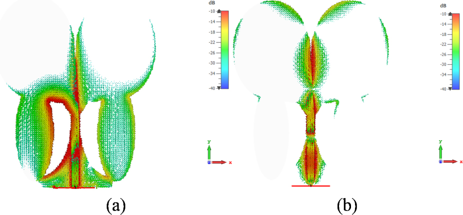
Figure 3: The surface current distribution of SELS-AVA at (a) 0.69 GHz and (b) 2.5 GHz.
The surface current distributions for optimized SELS-AVA at the frequencies of 0.69 GHz and 2.5 GHz are revealed in Fig. 3. At lower frequency, it can be seen that the electrical path for the current is significantly increased due to elliptical loaded strips, while the loaded strips have almost no contribution at the higher frequencies. As the frequency increases, the maximum surface current density focuses only on the central region of the antenna. It shows that the additional strips affect only performance at lower frequencies and causes to shift the lower frequency toward the left and hence contributing to miniaturize the aperture size of the antenna. So, for parametric analysis, the frequency range can be limited to only the sub-2GHz frequency band to reduce its computational cost.

Figure 4: SELS-AVA response for varying and constant : (a) return loss and (b) gain.
B. Parametric analysis
The SELS-AVA design is analyzed for different values of and only in the sub-2 GHz frequency band to reduce the computational cost. The sub-2GHz response of SELS-AVA is elaborated in Fig. 4, in terms of its return loss and gain by varying the parameter while keeping the constant. It can be seen that the lower cut-off frequency can be shifted towards the left by increasing . However, if the value of is increased by more than 40 mm then a narrow-band notch is started to create at about 800 MHz.
Similarly, the effect of varying while keeping constant on the return loss and gain in the sub-2GHz band is explained in Fig. 5. Varying has a negligible effect on the lower cutoff frequency and gain performance. After the detailed parametric analysis of SELS-AVA parameters, the optimum values of and are finalized and listed in Table 1.

Figure 5: SELS-AVA response for varying and constant . (a) Return loss and (b) gain.
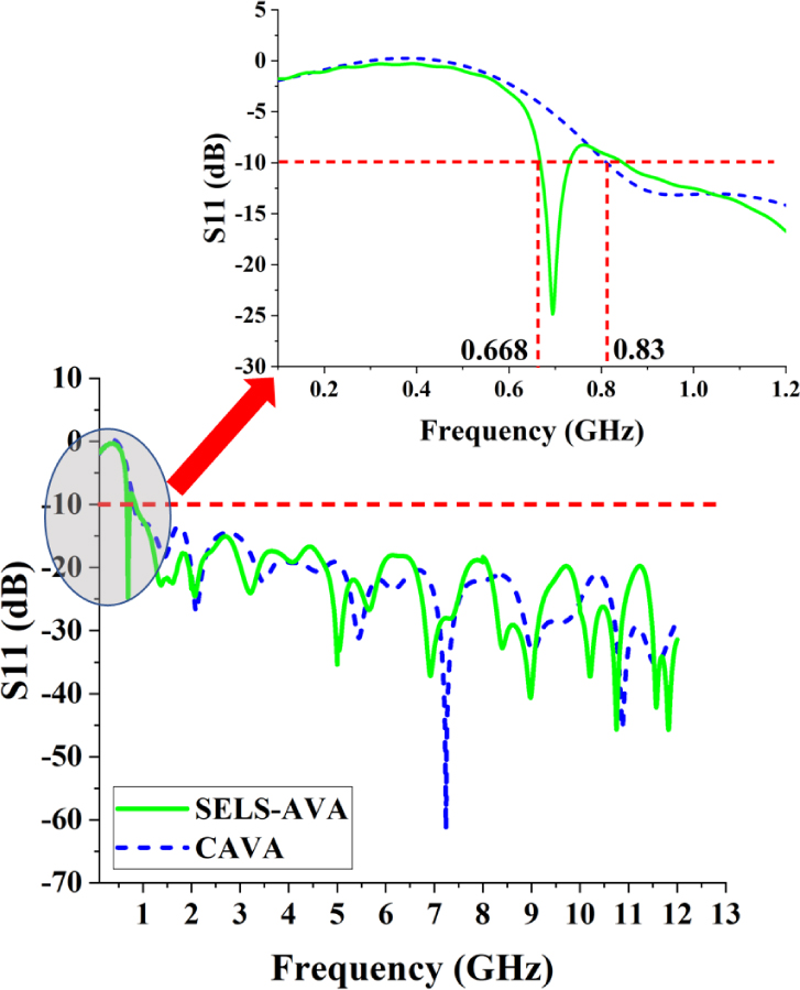
Figure 6: Simulated return loss of CAVA and SELS-AVA.
III. COMPUTATIONAL PERFORMANCE AND DISCUSSION
The addition of conducting strips contributes to extend the lower frequency range. The return loss of SELS-AVA is compared with that of CAVA and is plotted in Fig. 6. It can be seen that the lower cut-off frequency for SELS-AVA is 0.668 GHz as compared to 0.83 GHz for CAVA. So the size is reduced to 0.359 x 0.312 , which is a 19.5 size reduction as compared to the size of CAVA.
In this study, the proposed design is simulated and evaluated using two different computational techniques, one is Finite Difference Time-Domain (FDTD) method and the other is the Finite Element Method (FEM). CST Microwave Studio is used to implement both the mentioned computational techniques. These computational techniques are also compared to highlight the significance of the most suitable technique for miniaturization of a wideband antenna (0.668 to more than 14 GHz) with a common PC (2.59 GHz Core i3 processor with 8 GB memory).
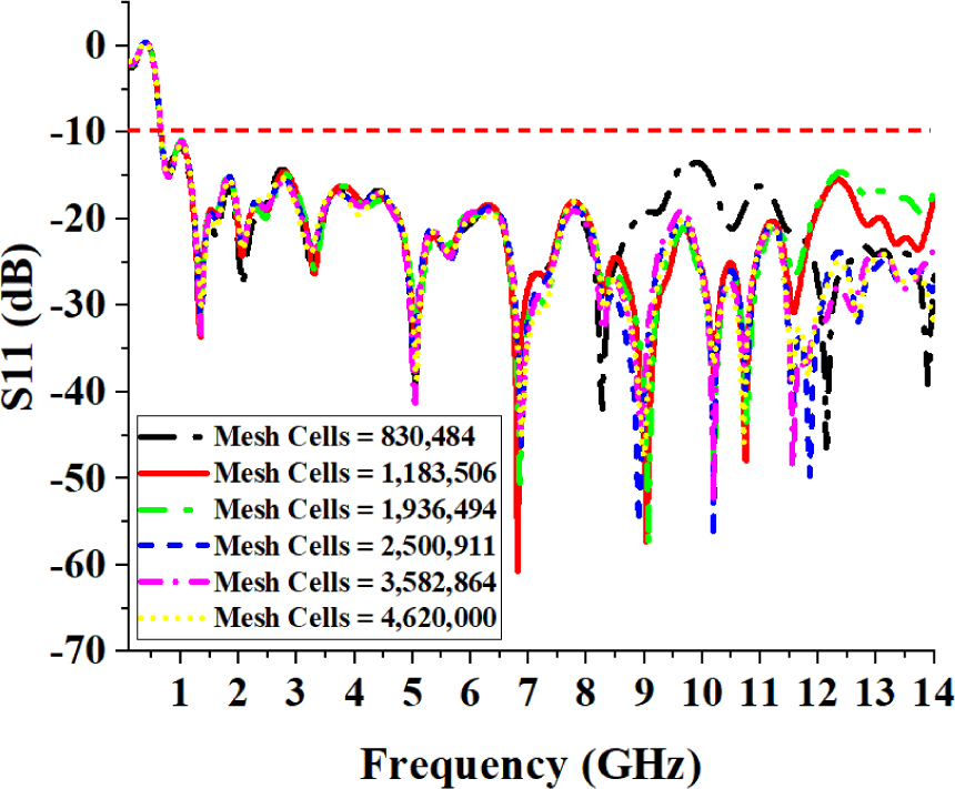
Figure 7: Return loss of SELS-AVA for varying mesh density using FDTD.
Several simulations are carried out using FDTD with an increasing number of mesh cells until convergence is achieved. Table 2, lists the FDTD statistics of the simulations for the proposed SELS-AVA design.
Table 2: FDTD statistics for SELS-AVA in wideband
| Cells per wavelength near the model | Smallest cell size (mm) | Largest cell size (mm) | Total hexahedral cells | Run time (M:S) |
|---|---|---|---|---|
| 5 | 0.524933 | 3.54365 | 830,484 | 3:29 |
| 6 | 0.49375 | 3.54365 | 1,183,506 | 7:53 |
| 7 | 0.3937 | 2.65773 | 1,936,494 | 34:9 |
| 8 | 0.3937 | 0.265773 | 2,500,911 | 40:09 |
| 9 | 0.33333 | 2.12619 | 3,582,864 | 45:06 |
| 10 | 0.31496 | 2.12619 | 4,620,000 | 32:07 |
The return loss for various mesh densities is shown in Fig. 7. It can be seen that the return loss is converged for greater than 2,500,911 hexahedral mesh cells and the lowest cutoff frequency is obtained at0.668 GHz.
Similarly, the proposed design is analyzed using the FEM solver by increasing the number of tetrahedron mesh cells. The FEM computation statistics for various mesh densities are summarized in Table 3 and corresponding results for return loss are plotted in Fig. 8. It can be seen that the FEM takes appreciably long computation duration for wideband simulations as the mesh density increases and convergence is also really hard to achieve in this case.
As, FEM is considered a more efficient technique for narrow band applications, so, the proposed design is analyzed in narrow-band continuous chunks of the whole wide frequency band as shown in Table 4. This way to analyze a wideband antenna using FEM in small chunks of the wide frequency bands helps a lot to achieve converged results with considerably less computational cost as compared to FEM analysis for the whole frequency band in a single run; however, its computational cost is still higher than that of FDTD analysis. Therefore, FDTD is more computationally efficient than FEM for the analysis of the proposed SELS-AVA. However, the computational cost of FEM can also be reduced significantly by its analysis in small continuous chunks of the whole frequency band instead of analysis for the whole frequency band in a single run.
Table 3: FEM statistics for SELS-AVA in wideband
| Max. no. of passes | Min edge length | Max edge length | Average quality | Total tetrahedrons | Run time (H:M:S) |
|---|---|---|---|---|---|
| 5 | 0.0608401 | 9.67442 | 0.755319 | 280,804 | 00:30:51 |
| 6 | 0.029147 | 9.49687 | 0.757769 | 446,414 | 00:17:41 |
| 7 | 0.0274142 | 9.51305 | 0.759502 | 611,627 | 00:15:11 |
| 15 | 0.0153071 | 9.44517 | 0.7606 | 799,307 | 21:44:42 |
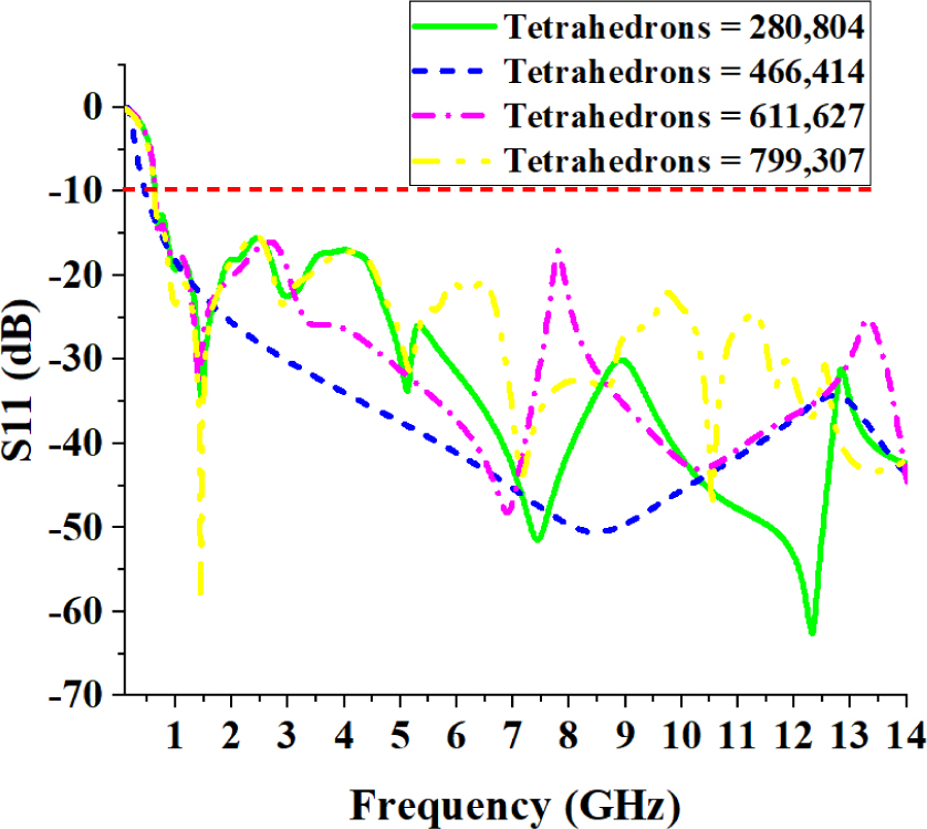
Figure 8: Return loss for SELS-AVA with varying mesh density using FEM.
Table 4: FEM statistics for SELS-AVA in small chunks of the frequency band
| Frequency bands (GHz) | Max no. of passes | Total tetrahedrons | Run time (M:S) |
|---|---|---|---|
| 0.1 – 2 | 8 | 26,938 | 00:03 |
| 2 – 5 | 8 | 39,993 | 01:25 |
| 5 – 8 | 8 | 90,214 | 16:53 |
| 8 – 10 | 8 | 123,306 | 06:35 |
| 10 – 12 | 8 | 111,993 | 05:13 |
| 12 – 14 | 8 | 227,263 | 06:34 |
The comparison of the converged return loss curves for FDTD and FEM analysis for the proposed antenna is shown in Fig. 9. It can be seen that the return loss curves for both the computational techniques are in close agreement.
Table 5: Comparison of proposed SELS-AVA with some other AVAs in literature
| Ref. | Frequency band (GHz) | Size ( x ) | Gain (dBi) | |
|---|---|---|---|---|
| [8] | 0.83 – 9.8 | 0.446 x 0.39 | 2.33 | 9.1 |
| [12] | 11.02 – 40 | 0.84 x 0.367 | 2.2 | 2.15 – 5.75 |
| [11] | 3 – 10.6 | 0.45 x 0.486 | 4.4 | 8.45 |
| [17] | 5.2 – 40 | 0.66 x 0.68 | 2.2 | 0.6 – 13.9 |
| [10] | 25 – 33.4 | 0.67 x 0.4 | 4.4 | 5 – 9.53 |
| [9] | 1.14 – 2.6 | 0.6 x 0.5 | 4.15 | 8.2 |
| SELS-AVA | 0.668 – 20+ | 0.359 x 0.31 | 2.65 | 9.4 |
The simulated gain of the proposed SELS-AVA is compared with that of CAVA in the Fig. 10. The peak gain offered by CAVA and SELS-AVA is 9.1 dBi and 9.5 dBi respectively. Although the peak gains offered by the two designs are similar, however, the performance of proposed antenna also exhibits suitable gain in sub-GHz frequency ranges.
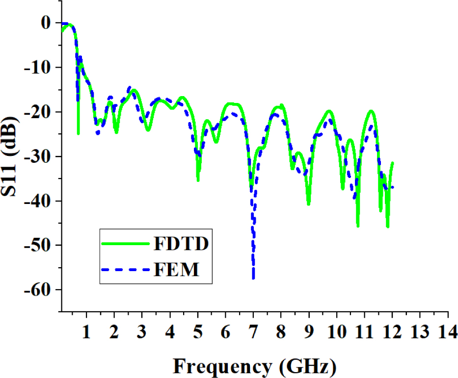
Figure 9: Comparison of return loss curves for FDTD and FEM.
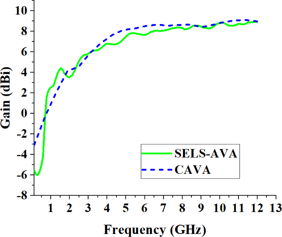
Figure 10: Simulated gain of SELS-AVA in comparison with CAVA.
The proposed SELS-AVA is compared with some other recent AVAs presented in the literature. The comparison is summarized in Table 5. The comparison is in terms of the operational frequency range, dielectric used, antenna size, and gain. It can be seen that the proposed technique achieves size reduction in the sub-GHz frequency band with a very simple technique and its performance is also comparable with existing techniques.
IV. CONCLUSION
In this work, computational analysis for miniaturization of the conventional AVA using FDTD and FEM is presented. The size of the conventional antenna is reduced intuitively by increasing the electrical path of the current by loading elliptical strips at the point, which has a maximum current density at lower frequencies, only. The size of the proposed SELS-AVA design is 0.359 x 0.312 , which is 19.5 smaller as compared to the size of CAVA. The gain of the proposed SELS-AVA design is 1.3 – 2.2 dBi in the sub GHz range of 0.668 – 1 GHz and an appreciable gain level over the entire operating range otherwise. The proposed design is simulated in FDTD and FEM solver and the results are counter-verified. The FDTD is a more efficient way to analyze the proposed antenna with less computational and memory resources. However, FEM can also be used efficiently for analysis and verification of the results of such antenna with a common PC if the analysis is carried out in small continuous chunks of the whole frequency band instead of the analysis for the whole frequency band in a single run. The antenna performance, compact size, and non-complexity make it a good addition to the antenna family for ultra-wideband applications and sub-GHz applications.
REFERENCES
[1] S. Raksanta, P. P. Kumar, and P. Saxena, “A sub-1GHz rectangular dielectric resonator antenna for IoT,” in Proc. 2019 IEEE Int. WIE Con. Electr. Comp. Eng. (WIECON-ECE), pp. 1-4, IEEE, 2019.
[2] M. Moundher, B. Hichem, T. Djamel, and S. Said, “Novel four-dimensional chaotic oscillator for sub-1GHz chaos-based communication systems,” in Proc. 2019 6th Int. Conf. Image Signal Process. Appl. (ISPA), pp. 1-5, IEEE, 2019.
[3] A. Sharma, B. Mishra, R. Sutaria, and R. Zele, “Design and development of low-cost wireless sensor device for air quality networks,” in Proc. TENCON 2019-2019 IEEE Region 10 Conf. (TENCON), pp. 2345-2350, IEEE, 2019.
[4] A. Benayad and M. Tellache, “Broad band rectenna based on Antipodal Vivaldi antenna and NULT rectifier,” in Proc. 2020 2nd Int. Workshop Human-Centric Smart Environ. Health Well-being (IHSH), pp. 40-43, IEEE, 2021.
[5] K. N. Salim, M. R. Fairuzi, M. R. Sutoyo, and F. Y. Zulkifli, “Wideband Vivaldi microstrip antenna for rectenna application,” in Proc. 2020 Int. Seminar Intell. Technol. Its Appl. (ISITIA), pp. 317-320, IEEE, 2020.
[6] D. Yang, S. Liu, and D. Geng, ‘‘A miniaturized ultra-wideband Vivaldi antenna with low cross polarization,” IEEE Access, vol. 5, pp. 23352-23357, 2017.
[7] M.-A. Boujemaa, R. Herzi, F. Choubani, and A. Gharsallah, “UWB Antipodal Vivaldi antenna with higher radiation performances using metamaterials,” Appl. Phys. A, vol. 124, no. 10, pp. 1-7, 2018.
[8] J. Y. Siddiqui, Y. Antar, A. Freundorfer, E. Smith, G. Morin, and T. Thayaparan, “Design of an ultrawideband antipodal tapered slot antenna using elliptical strip conductors,” IEEE Antennas Wireless Propag. Lett., vol. 10, pp. 251-254, 2011.
[9] A. Loutridis, S. Kazıcı, O. V. Stukach, A. B. Mirmanov, and D. Caratelli, “A novel class of super-elliptical Vivaldi antennas for ultra-wideband applications,” Adv. Radio Frequency Antennas Modern Commun. Medical Syst., 2020.
[10] A. S. Dixit and S. Kumar, “The enhanced gain and cost-effective Antipodal Vivaldi antenna for 5G communication applications,” Microw. Opt. Technol. Lett., vol. 62, no. 6, pp. 2365-2374, 2020.
[11] S. Guruswamy, R. Chinniah, and K. Thangavelu, “Design and implementation of compact ultra-wideband Vivaldi antenna with directors for microwave-based imaging of breast cancer,” Analog Integrated Circuits Signal Process., vol. 108, no. 1, pp. 45-57, 2021.
[12] J.-Y. Deng, R. Cao, D. Sun, Y. Zhang, and L.-X. Guo, “Bandwidth enhancement of an Antipodal Vivaldi antenna facilitated by double-ridged substrate-integrated waveguide,” IEEE Trans. Antennas Propag., vol. 68, no. 12, pp. 8192-8196, 2020.
[13] Z.-F. Yin, X.-X. Yang, and T. Lou, “A high gain UWB Vivaldi antenna loaded with elliptical slots,” in Proc. 2018 Int. Appl. Comput. Electromagn. Soc. Symp.-China (ACES), pp. 1-2, IEEE,2018.
[14] M. A. Ashraf, K. Jamil, A. Sebak, M. Shoaib, Z. Alhekail, M. Alkanhal, and S. Alshebeili, “Modified Antipodal Vivaldi antenna with shaped elliptical corrugation for 1-18 GHz UWB application,” Appl. Comput. Electromagn. Soc. J. (ACES), pp. 68-77, 2015.
[15] Y. Zhu, D. Su, W. Xie, Z. Liu, and K. Zuo, ‘‘Design of a novel miniaturized Vivaldi antenna with loading resistance for ultra wideband (UWB) applications,” Appl. Comput. Electromagn. Soc. J. (ACES), pp. 895-900, 2017.
[16] J. Bai, S. Shi, and D. W. Prather, “Modified compact antipodal Vivaldi antenna for 4-50-GHz UWB application,” IEEE Trans. Microw. Theory Techn., vol. 59, no. 4, pp. 1051-1057, 2011.
[17] Z. Yin, X.-X. Yang, F. Yu, and S. Gao, “A novel miniaturized antipodal Vivaldi antenna with high gain,” Microw. Opt. Technol. Lett., vol. 62, no. 1, pp. 418-424, 2020.
ACES JOURNAL, Vol. 37, No. 6, 672–678.
doi: 10.13052/2022.ACES.J.370603
© 2021 River Publishers