Study on the Electromagnetic Interference of Shielded Cable in Rail Weighbridge
Yang Yang, Feng Zhu, Nan Lu, and Yingchun Xiao
1School of Electrical Engineering, Southwest Jiaotong University, Chengdu 610031, China
280899254@qq.com, zhufeng@swjtu.cn, lunan946@qq.com, 1134748712@qq.com,
2Department of Railway Engineering, Sichuan College of Architectural Technology, Deyang 618000, China
Submitted On: September 14, 2021; Accepted On: February 16, 2022
Abstract
In view of the electromagnetic interference (EMI) of the signal shielded cable in the rail weighbridge, the interference source is analyzed on the basis of the field measurement and investigation, and methods of suppressing the crosstalk voltage of the shielded cable are proposed. First, the capacitive coupling model between the power line and the shielded cable is established, and the coupling model between the shielded layer and the core is developed. Later, the distribution parameters of the multi-conductor transmission line system are extracted by the commercial software ANSYS based on the finite element method. Then the coupling voltages of the shielded layer and the core can be calculated; compared with the measured results, the accuracy and effectiveness of the proposed method are verified. Finally, the EMI suppression methods are proposed and its effectiveness is verified. The EMI of the shielded cable is very common in engineering, and this method has a good reference value for solving the similar problems.
Keywords: Capacitive coupling, crosstalk voltage, electromagnetic interference, rail weighbridge, shielded cable.
I. INTRODUCTION
The electronic rail weighbridge is an electronic weighing device for weighing railway vehicles and goods [1]. China’s railway capacity is increasing with the development of railway transportation, and it is necessary to weigh the railway vehicles and their loaded goods more efficiently and accurately; so the electronic rail weighbridge must work in electromagnetic compatibility (EMC). However, research on the influence of shielding and grounding of railway field on electromagnetic interference (EMI) is still in an initial stage [2-4]. Therefore, the research on crosstalk of shielded signal cable of rail weighbridge has theoretical and practical application values [5].
Nowadays, the crosstalk researches of multi-conductor transmission lines are mainly concentrated in the high frequency band [6-9]; so they cannot be applied at low frequency for signal interference analysis. In some articles, single-end grounding of signal cable is proposed to solve the problem of EMI [10-12]. However, due to the complex electromagnetic environment in actual railway fields, even if the single-end grounding is used, there is still serious interference; so there is still lack of systematic theoretical analysis of railway electromagnetic environment. In a rail weighbridge EMI case, the rail weighbridge is set beside the National Traction Power Laboratory (NTPL) in Chengdu, China. The pressure sensor on the rail weighbridge is an electronic device that converts the weight of cargo and vehicles into an electrical signal. It is supposed to show a zero signal when there is nothing on the rail weighbridge, but in the EMI case, it shows a 320-mV electrical signal. The electric field intensity around the signal cable about 400 V/m is also measured by using an electric field tester, showing that the EMI is serious.
In Section II of this paper, the capacitive coupling model of signal transmission cable and power line under low frequency of railway weighbridge is established, and the formula for calculating the potential of the shielded layer as well as the crosstalk voltage between the shielded layer and the core of the signal cable is derived. In Section III, based on actual measurement and the finite element software ANSYS [13, 14], the coupling capacitance of multi-conductor line system is extracted and the interference voltage is calculated. In Section IV, the measures such as increasing the depth of grounding rods and improving soil moisture are proposed. Combined with an EMI case of railway weighbridge, the cause of interference signal is analyzed and eliminated. In Section V, the conclusion is drawn. The theoretical correctness is verified by comparing with the measured value in the field.
II. SIGNAL CABLE INTERFERENCE MODEL OF RAIL WEIGHBRIDGE
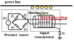
The working circuit and signal interference diagram of the pressure sensor on the rail weighbridge is shown in Figure 1. The pressure sensor is mainly composed of four varistors to form the Wheatstone bridge (consists of R-R and DC power supply). Its function is to convert the weight of the goods on the rail weighbridge into electrical signals. These electrical signals are sent through shielded cable to operational amplifier, filter, and other signal processing device, and finally the display will present the electrical signal to the user in terms of voltage signal and the weight of the goods.
The structure of the shielded cable used in the rail weighbridge is shown in Figure 1. It is composed of a copper mesh shielding layer and two core wires. Under ideal conditions, the shielding layer can protect the core wires from external electrical signal interference. However, when the shielded cable is very close to other wires, especially a power line with a large current, the power line can be regarded as a source of interference. Through capacitive coupling between multiple conductors, the shielding layer of the shielded cable can be regarded as the interfered object, and the induced charges will be generated on it. If the grounding resistance R of the shielding layer is large, the electric field of the induced charges on the shielding layer will generate interference voltage on the cable core [15].
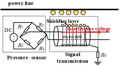
Figure 1: Circuit and signal interference diagram of the pressure sensor.
A. The crosstalk model of shielded layer and power line
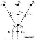
When the signal cable is near the power line, due to the capacitive coupling between multiple conductors, the induced charges will be coupled on the shielded layer [16]. As shown in Figure 2, the shielded layer O is close to the power line. A, B, and C, respectively, represent the fire, zero, and ground wires of the power line. The capacitance between the shielded layer and the power lines A, B, and C is C, C, and C, the capacitance of the shielded layer to the ground is C, the interference voltage on the shielded layer is U, and the voltages on the three lines A, B, and C are U, U, and U.
According to the model of multi-conductor transmission lines, in a system consisting of three or more charged conductors, the charge of any conductor is affected not only by its own voltage but also by the voltages of the other conductors [17]. Then the charge Q on the shielded layer can be expressed as [18]
| (1) |
where represents the electrostatic induction coefficient of the shielded layer; , , and represent the mutual electrostatic induction coefficients of the signal cable and the three-phase transmission lines. The relation between and C is [19]
| (2) |
| (3) |
| (4) |
According to the Thevenin theorem, the power line, shielding layer, and the ground can be regarded as a two-port network with an ideal voltage source in series with a resistor. The parameters of the voltage source and the resistor can be obtained by the following methods.
Consider two extreme cases: (1) perfect insulation of signal cable to ground; (2) short circuit of signal cable to ground. i represents the short-circuit current of the signal cable when it short-circuits to the ground.
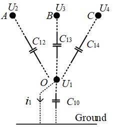
Figure 2: Coupling model of power cord and shield wire.
When the signal cable is perfectly insulated from the ground, Q= 0. According to eqn (1), the open-circuit voltage of the signal cable is
| (5) |
When the signal cable is short-connected to the ground, the signal cable voltage U is 0, and then its induced charge is
| (6) |
In the case of alternating current 50 Hz, charge Q is related to short-circuit current i [20], which can be expressed as
| (7) |
According to the Thevenin theorem, the power line, the shielded layer, and the ground can be regarded as the two ends of the power supply with the open-circuit voltage U and short-circuit current i. The internal impedance of power supply is
| (8) |
The grounding resistance R of the shielded layer of the signal cable is related to the soil conductivity, temperature, humidity and grounding wire wiring measures at the grounding site [21, 22], and the grounding resistance value must comply with the national standard [23]. At this time, the disturbance voltage on the shielded layer of the signal cable is [24]
| (9) |
In the ideal case, the earth is equipotential, but, in fact, there is a potential difference between any two points on the earth; so, the shielded layer will have great potential when the grounding device selection is inappropriate, the soil resistivity is excessive, or the potential gradient of the soil is large, especially near the high power equipment. Therefore, the potential of the shielded layer of the signal cable is equal to the vector sum of the ground potential and the induced voltage, and the calculation formula is as follows [25]:
| (10) |
where U represents the total disturbance voltage of the shielded layer, U is the increased ground potential, and U is the induced voltage of the transmission line.
B. The coupling voltage of the shielded layer and core of the signal cable
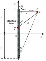
For the sensor signal cable, the disturbance voltage on the shielded layer produces interference voltage on the core through electric field coupling, which will have a serious impact on the useful signal after amplification. The electric field intensity model generated by the shielded layer voltage is shown in Figure 3. The shielded layer with line charge density is 2l in length, and the center point of the conductor is selected as the origin to establish a Cartesian coordinate system.
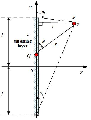
Figure 3: A model of the electric field generated by the voltage of shielded layer.
According to the Coulomb’s law and the concept of potential, the potential generated by point q on the shielded layer to any point P is [26]
| (11) |
| (12) |
| (13) |
| (14) |
| (15) |
where r and z are the horizontal and vertical distances of points P and q, the angle between the point q and the y-axis is , the angles between the two ends of the shielded layer and y-axis are, respectively, and , and is the vacuum permittivity. Replacing eqn (12)-(15) into eqn (11), it can be derived:
| (16) |
In the actual situation, on the surface of the shielded layer, z l and r l, eqn (16) can be derived:
| (17) |
According to the Gauss law, the electric field E can be expressed as
| (18) |
Then the interference voltage U on the core of the signal cable can be obtained:
| (19) |
where d is the distance between the shielded layer and the core of the signal cable.
III. ANALYSIS OF TEST AND SIMULATION RESULTS
A. A case study on the EMI of rail weighbridge
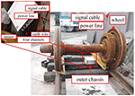
We have participated in an EMI case of a rail weighbridge. The physical layout of the rail weighbridge is shown in Figure 4. In the figure, the pressure sensor of the yellow rail weighbridge is connected with the outer chassis through a signal cable. The power line and signal cable behind the outer chassis are very close to each other. The internal structure of the outer chassis is shown in Figure 5. The collected data is transmitted to the amplifier through CH0, CH1, CH2, and CH3 channels.
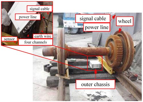
Figure 4: Layout of the device for rail weighbridge.
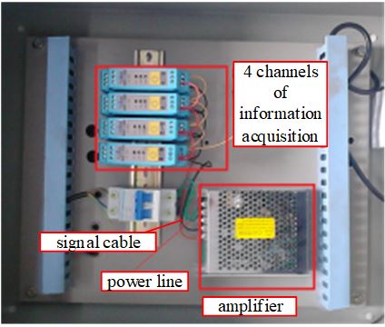
Figure 5: Internal structure diagram of external chassis of rail weighbridge.
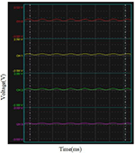
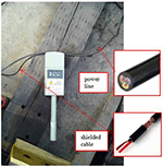
It was found that even without cargo on the rail weighbridge, the voltage signal still displayed an interference voltage on the core of the cable, as shown in Figure 6. The exact value of the interference voltage derived from the exported table was 320 mV in maximum. The crosstalk voltage of the shielded layer was measured to be about 105 V, and the electromagnetic intensity beside the signal cable was measured to be about 400 V/m by using the electric field tester, as shown in Figure 7. There was a great interference voltage on the core of the signal cable, which affected the normal usage of the rail weighbridge.
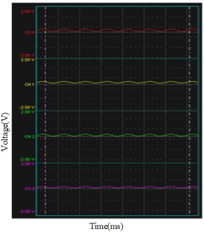
Figure 6: Four channels of interference voltage signal displayed on the screen.
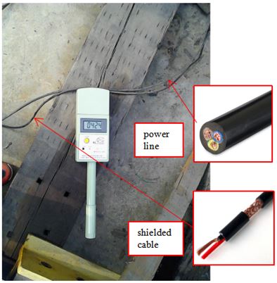
Figure 7: Testing picture of the electric field intensity.

Figure 8: Power line, signal cable, and ground modeled by finite element method.
B. Simulation and coupling capacitance extraction
In this case, the signal cable adopts RVVP double-core shielded cable, the insulating material is PVC (polyvinyl chloride), the shielding layer is copper braid, the cable diameter d is 7.6 mm, the diameter of the core is 3 mm, the power line adopts RVV three-core cable, the cable diameter is 7.9 mm, and the diameter of the core is 2.8 mm. The two cables are 1-mm apart in close proximity and 0.5 mm above the ground. The finite element model of the shielded cable and power line is shown in Figure 8.
Through the analysis of finite element software ANSYS [27], the ground wire, fire wire, and zero wire in the power line constitute the multi-conductor transmission lines coupling system. The coupling capacitance between them can be extracted as 27.83, 27.62, and 6.29 pF, which represent C, C, and C, respectively, and the coupling capacitance C is 71.31 pF. Some actual parameters are obtained in the measurement: is 105 V, l is 5 m, and r is 7.9 mm. According to formula (9) mentioned above, the shield-power cord crosstalk voltage U is 102.1 V. According to formulae (16) and (17), the electric field intensity of the shielded layer E is 413 V/m. Substituting the diameter d of the shielded cable as 7.6 mm into formula (19), the crosstalk voltage of the core of the signal cable which is represented by U is 316 mV.
The calculated values of the proposed method are basically consistent with the measured data, which verified the accuracy of the proposed method for interference prediction of railway weighbridge system.
III. APPLICATION AND MEASURES FOR IMPROVEMENT
From the above, we know that the power line of the rail weighbridge system will generate interference voltage in the signal cable, resulting in a large error in the output signal voltage. The coupling capacitance of the shielded layer and the core, the length of the signal cable are fixed, they are not easy to be changed. Therefore, measures to reduce low-frequency crosstalk voltage of core can be mainly divided into increasing shielding protection measures and reducing ground potential [28, 29], as follows.
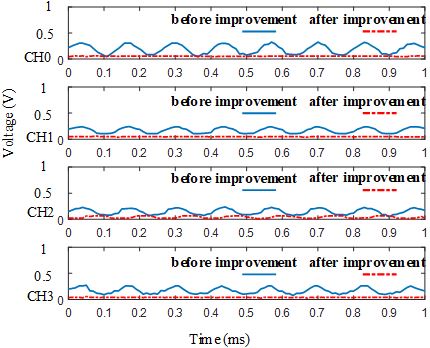
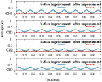
Figure 9: Comparison of interference voltage of the signal before and after improvement.
1) To improve the joint between the signal cable and the equipment, using the shielded cable with good shielded performance can reduce the coupling path of EMI.
2) To improve the grounding condition, increasing the contact area and depth of the grounding rod can reduce the soil resistivity.
3) When the surface potential gradient of the shielded cable is large, it is suitable to increase the number of grounding rods to reduce the surface potential difference.
After on-site inspection, there are some high-power equipment in the laboratory; so the induced voltage of the earth’s surface is large, the depth grounding rod is not enough, and the soil is dry. Therefore, the methods of increasing the grounding depth from 0.1 to 0.6 m, increasing the moisture of soil, increasing the number of grounding rods from 1 to 4, and replacing the joints of the shielded cable are adopted.
After the improvement, the test shows that the interference voltage is basically reduced to 2 mV, and the electric field intensity near the power line is reduced to about 5 V/m. The comparison of the signal interference voltage before and after the improvement in the display is shown in Figure 9, in which the solid blue line is the interference voltage before suppression, and the dashed red line is the interference voltage after suppression in the absence of pressure. By comparison, the maximum crosstalk voltage decreases from 320 to 2 mV, and the inhibition effect of the proposed method is significant.
III. CONCLUSION
This paper studies the EMI of the signal cable in railway weighbridge. The multi-conductor transmission lines model is established with the power line and signal cable, and the use of software for the simulation and calculation verifies the validity of the model. Then, as to an actual case of EMI, some applications such as replacing the shielded cable’s joints and improving the grounding devices to restrain EMI had been proposed. Finally, the interference voltage on the signal cable had been eliminated. The inhibition effect of the proposed method is significant. This kind of EMI for shielded cable is very common in engineering, and the methods have good reference value for solving the similar problems.
ACKNOWLEDGMENT
This work was supported in part by the National Key R&D Program of China under Grant 2018YFC0809500.
REFERENCES
[1] Y. Zhou, H. Jiang, S. Li, A. An, and L. Bai, “Present situation of railway scale technology,” in Metering Technology of Track Scale .Beijing,China. Science Press, pp. 2-5, 2017.
[2] Y. Cui, S. Yong, Z. Liu, and Y. Wang, “Research on shielding and grounding mode of railway signal cable,” Journal of the China Railway Society, vol. 39, no. 17, pp. 77-82, Nov. 2017.
[3] B. Yi, Z. Wang. “Parameters calculation of shield cable and crosstalk between shielded layer and core,” High Voltage Engineering, vol. 04, pp. 804-808, Apr. 2008.
[4] Z. Han, B. Li, and Z. Guo. “Discussion on earthing anti-jamming technology,” Measurement and Control Technology, vol. 23, no. 12, pp. 74-77, Dec. 2007.
[5] F. Lin, Z. Yao, and X. Dai, “Numerical calculation of common-model interference coupled in a shielded cable,” High Voltage Engineering, vol. 23, no. 4, pp. 9-11, Dec. 1997.
[6] C. Taylor, R. Satterwhite, and C. Harrison, ‘The response of a terminated two-wire transmission line excited by a nonuniform electromagnetic field,” IEEE Transactions on Antennas & Propagation, vol. 13, no. 6, pp. 987-989, Dec. 1965.
[7] V. Teppati, M. Goano, A. Ferrero, “Conformal-mapping design tools for coaxial couplers with complex cross section,” IEEE Transactions on Microwave Theory and Techniques, vol. 50, no. 10, pp. 2339-2345, Nov. 2002.
[8] P. Xiao, W. Ran, and P. Du, “An analytic method of determining a critical cable spacing for acceptable crosstalk,” Applied Computational Electromagnetics Society (ACES) Journal, vol. 35, no. 2, pp. 237-277, Feb. 2020.
[9] L. Li, W. Li, X. Wang, and W.-B. Li, “Crosstalk analysis between two parallel transmission lines,” Chinese Journal of Radio Science, vol. 16, no. 2, pp. 271-274, Jun. 2002.
[10] Q. Yu, W. Liu, K. Yang, X. Ma, and T. Wang “Uncertainty quantification of the crosstalk in multiconductor transmission lines via degree adaptive stochastic response surface method,” Applied Computational Electromagnetics Society (ACES) Journal, vol. 36, no. 2, pp. 174-183, Feb. 2021.
[11] A. Djordhevic and T. K. Sarkar, “Analysis of time response of lossy multiconductor transmission line networks,” IEEE Transactions on MTT, vol. 35, no. 10, pp. 898-908, Nov. 1987.
[12] M. Z. M. Hamdalla, A. N. Caruso, and A. M. Hassan, “Predicting electromagnetic interference to a terminated wire using characteristic mode analysis,” Applied Computational Electromagnetics Society (ACES) Journal, vol. 35, no. 11, pp. 1318-1319, Nov. 2020.
[13] Z. He, Z. Li, P. Liang, “ANSYS calculation method of temperature and current-carrying capacity for transmission lines,” Zhejiang Electric Power, vol. 8, pp. 1-5, 2010.
[14] C. Zhu, W. Yan, S. Liu, and L. Geng, “Analysis on crosstalk for coplanar irregular-placed cables based on cascading method and cubic spline interpolation algorithm,” Applied Computational Electromagnetics Society (ACES) Journal, vol. 35, no. 5, pp. 572-579, May 2015.
[15] G. Vijayaraghavan, M. Brown, and M. Barnes, “Equipment grounding,” in Practical grounding, bonding, shielding and surge protection. 3th ed. Butterworth-Heinemann, pp. 24-37, 2004.
[16] C. R. Paul, “Solution of the transmission-line equation for three-conductor lines in homogeneous media,” IEEE Trans. Electromagnetic compatibility. vol. 20, no. 1, pp. 216-222, Mar.1978.
[17] J. Bai, G. Zhang, L. Wang, A. Duffy, C. Liu, and T. Shao, “Comparison of calculation methods of braided shield cable transfer impedance using FSV method,” Applied Computational Electromagnetics Society (ACES) Journal, vol. 30, no. 2, pp. 140-147, Feb. 2015.
[18] C. R. Paul, Analysis of Multiconductor Transmission Lines. New York, USA: Wiley, 1994.
[19] C. Feng and X. Ma, An introduction to engineering electromagnetic fields, Higher Education Press, pp. 46-51, 2018.
[20] R. Morrison, “Electromagnetic compatibility,” in grounding and shielding techniques. 4th ed. New York, Wiley, 1998.
[21] R. Xiong, Q. Yin, W. Yang, Y. Liu, and J. Li, “Improvement of shaped conductive backfill material for grounding systems,” Applied Computational Electromagnetics Society (ACES) Journal, vol. 36, no. 4, pp. 442-449, Apr. 2021.
[22] J. Ma and F. P. Dawalibi, “Analysis of grounding systems in soils with finite volumes of different resistivities,” IEEE Power Engineering Review, vol. 17, no. 2, pp. 596-601, Apr. 2002.
[23] Code for Electrical Design of Civil Buildings, JGJ16-2008, Ministry of Construction of the People’s Republic of China, 2008.
[24] H. Lu, Z. Yu, and W. Li, Electronic Information Specialty, Xian, China, Xidian University Press, 2012.
[25] S. W. Blume, “Critical telecommunications circuits in HV environments,” in High Voltage Protection for Telecommunications, Wiley-IEEE Press, pp. 121-142, 2011.
[26] D. K. Chen, Field and Wave Electromagnetics, Pearson education, pp. 49-72, 2013.
[27] Q. Q. Liu, Y. Zhao, C. Huang, W. Yan, and J. M. Zhou. “A new method for stranded cable crosstalk estimation based on BAS-BP neural network algorithm combined with FDTD method,” Applied Computational Electromagnetics Society (ACES) Journal, vol. 35, no. 2, pp. 135-144, Feb. 2020.
[28] W. Huang, W. Liang, and X. Wen, “Method of reducing the grounding impedance of yangjiang nuclear power plant,” High Voltage Engineering, vol. 36, no. 2, pp. 365-370, Feb. 2010.
[29] Z. Lu, S. Chang, and X. Wen, “Numerical analysis of grounding impedance for grounding grids with multi points short circuit current into the ground,” High Voltage Engineering, vol. 30, no. 10, pp. 15-16, Oct. 2004.
BIOGRAPHIES

Yang Yang was born in Shanxi, China, on April 19, 1989. She received the master’s degree in control theory and control engineering from Northwestern Polytechnical University in 2014. She is currently working toward the Ph.D. degree in electrical engineering with Southwest Jiaotong University, Chengdu, China. At the same time, she is also a Lecturer with the Sichuan College of Architectural Technology. Her research interests include electromagnetic environment test and evaluation, electromagnetic compatibility analysis, and design in the field of rail transit.

Feng Zhu received the Ph.D. degree in railway traction electrification and automation from the Southwest Jiaotong University, Sichuan, China, in 1997. He is currently a Full Professor with the School of Electrical Engineering, Southwest Jiaotong University. His current research interests include locomotive over-voltage and grounding technology, electromagnetic theory and numerical analysis of electromagnetic field, and electromagnetic compatibility analysis and design.

Nan Lu was born in Anhui Province, China, on June 3, 1990. He received the master’s degree in electrical engineering from the Anhui University of Science & Technology, Anhui, China, in 2016, and is currently working toward the Ph.D. degree in electrical engineering with Southwest Jiaotong University, Chengdu, China. His research interests include electromagnetic compatibility, electromagnetic environment test and evaluation, and transmission-line analysis.

Yingchun Xiao was born in Gansu Province, China, in 1990. She received the B.S. degree in electronic information science and technology from the Lanzhou University of Technology, Lanzhou, China, in 2012, and is currently working toward the Ph.D. degree in electrical engineering with Southwest Jiaotong University, Chengdu, China. At the same time, she is a Lecturer with Lanzhou City College. Her research interests include electromagnetic environment test and evaluation, electromagnetic compatibility analysis and design, and identification and location of electromagnetic interference sources.
ACES JOURNAL, Vol. 37, No. 2, 215–221.
doi: 10.13052/2022.ACES.J.370210
© 2021 River Publishers