Design Optimization of Ultra-Wideband Vivaldi Antenna using Artificial Intelligence
Peyman Mahouti, Ahmet Kızılay, Ozlem Tari, Aysu Belen, Mehmet A. Belen,
and Alper Çalışkan
1Department of Electronics and Automation, İstanbul University- Cerrahpaşa, İstanbul, Turkey
pmahouti@iuc.edu.tr
2Department of Electronic and Communication, Yıldız Technical University, İstanbul, Turkey
akizilay@yildiz.edu.tr, alperc@yildiz.edu.tr
3Department of Mathematics and Computer Science, İstanbul Arel University, İstanbul, Turkey
ozlemilgin@arel.edu.tr
4Department of Hybrid and Electric Vehicles Technology, İskenderun Technical University, Hatay, Turkey
aysu.belen@iste.edu.tr
5Department of Electric and Electronic, İskenderun Technical University, Hatay, Turkey
mali.belen@iste.edu.tr
Submitted On: September 16, 2021; Accepted On: December 21, 2021
Abstract
In this work, computationally efficient design optimization of frequency selective surface (FSS)-loaded ultra-wideband Vivaldi antenna via the use of data-driven surrogate model is studied. The proposed design methodology consists of a multi-layer FSS structure aimed for performance improvement of the Vivaldi design, which makes the design a multi-objective multi-dimensional optimization problem. For having a fast and accurate optimization process, a data-driven surrogate model alongside the metaheuristic optimizer honeybee mating optimization (HBMO) had been used. The optimally designed antenna had been prototyped and its performance characteristics had been measured. The obtained experimental results are compared with the simulated results of the proposed method. Results show that the obtained FSS-loaded structure has enhanced directivity compared with the design without FSS structure, without any performance losses in the return loss characteristics. The FSS-loaded Vivaldi antenna operates at 2–12 GHz band with a maximum gain of 10 dBi at 10 GHz which makes the design a good solution for RADAR applications.
Index Terms: Frequency selective surface, optimization, surrogate modeling, ultra-wideband, Vivaldi antenna.
I. INTRODUCTION
Due to their high-performance characteristics Vivaldi antenna designs are being used in many communication applications such as microwave imaging and ground penetrating radar (GPR) [1], [2]. In order to analyze the composition of underground soil, GPR requires to propagate high-power EM wave to the ground. In order to have a wide range of characterization of soil the signals need to go deep into the ground and have high resolution. For such capability the GPR antenna requires to operate in low frequency, have ultra-wideband characteristics, and high gain performance [3]. There are different types of antennas suitable for GPR applications with respect to their characteristics such as o GPR antenna dipole [4], bowtie [5], [6], and Vivaldi antennas [7], [8]. Due to its high gain, ultra-wideband characteristic, Vivaldi antenna can be named as one of the most commonly used antenna design for GPR applications. It should be noted that such designs usually require a large design space or smaller size with lower performance measures. Usage of lens structures can be named as one of the methods for performance improvement of antenna designs [9], [10]. However, although the placement of dielectric lens structures can increase the gain performance of antenna but their improvements are limited [11].
Another well-known solution for performance enhancement of antenna designs is the placement of frequency selective surfaces (FSS) to the aperture of the antenna in an optimally determined configuration such as: antenna design with a multi-layer S-type resonator with zero index for gain enhancement [12], design with multi-layers [13], [14] for gain enhancement, and [15] for sidelobe suppression of the antenna design. Although the application of FSS can provide a significant performance improvement to the design, the placement and the geometrical design of FSS structures must beoptimized to reach their full performance of improvement. Achieving such task requires a multi-objective multi-dimensional optimization process, which requires a considerable amount of trial and error. This process usually forces researchers to make a decision for their models. Either they should use a course model with low accuracy for achieving fast and computationally efficient design optimization or they must use fine meshed design with high accuracy at expanse of relatively long or infeasible design optimization process [16].
One of the most efficient solutions for having an accurate, reliable, and computationally efficient optimization process is the usage of data-driven surrogate models. Data-driven surrogate models had been used by many researches for applications such as parameter tuning [17], statistical analysis [18], [19], and multi-objective design [20]. In literature, there are many Artificial Intelligence (AI)-based methods for surrogate-based modeling of microwave structures such as polynomial regression [21], kriging interpolation [22], radial basis functions [23], support vector regression [24], polynomial chaos expansion [25], and artificial neural networks (ANN) [26].
In this work, for optimal determination of geometrical design variables of an FSS structure to be applied to an antipodal Vivaldi antenna (AVA) for performance improvements have been achieved via the use of data-driven surrogate modeling [27]. Firstly, an FSS-loaded Vivaldi antenna have been presented in Section II, alongside the design variables of FSS structure. By using Latin-hypercube sampling method, a data set generated with a 3D full-wave EM simulator is created to be used for data-driven surrogate model to create a mapping between geometrical design parameters of FSS structure and performance measures of scattering and maximum gain of the FSS-loaded Vivaldi antenna design. In Section III, some of the commonly used state of the art AI regression algorithms had been used and bench marked to obtain a model with best performance for creating a mapping between input and output of the data set. In Section IV, the optimal selected surrogate model will be used to drive the design optimization search alongside a meta-heuristic optimizer. Finally, the work ends with a brief conclusion in Section V.
II. FSS-LOADED VIVALDI ANTENNA
In Figure 1, a typical AVA design modeled in 3D CST MWS environment is presented. AVA is designed on a PLA Filament–Polar White RBX-PLA-WH002 ( = 2.5) with two noncoplanar exponentially tapered edge arms on both top and ground plane (symmetrically) of the antenna. The exponentially tapered edges of the design are defined as exponential factor R, P1(x, y), and P(x, y), initial and final points of the exponential tapered shape respectively. Design equations are given below as eqn (1)–(3) [28, 29]:
| (1) |
where
| (2) |
| (3) |
C = 5, C = 0, R = 0.03; and C = 15, C = –8, R = 0.1, respectively. In Figure 2, the simulated performance of the Vivaldi antenna without FSS structure had been presented.

Figure 1: A typical antipodal vivaldi antenna.
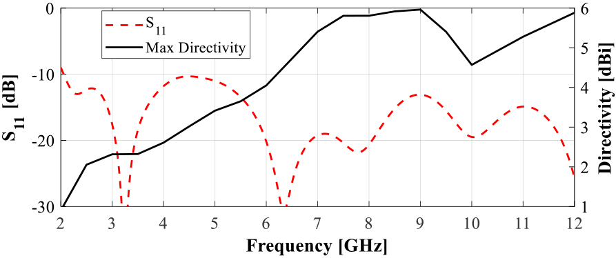
Figure 2: Simulated performance of the vivaldi antenna.
Table 1: Design variables and their variation limits
| Variable | Min | Max | Variable | Min | Max |
|---|---|---|---|---|---|
| W1 | 5 | 15 | L1 | 2 | 8 |
| S1 | 0.5 | 2 | H2 | 2 | 6 |
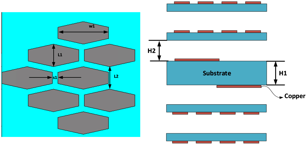
Figure 3: Schematic of the proposed FSS-loaded Vivaldi antenna.
In Figure 3, the schematic of the proposed FSS structure to be placed in top and ground layer sides of Vivaldi antenna is presented. The variables of the FSS structure and their lower and upper limitations are presented in Table 1. For ease of modeling, L2 is taken as equal to L1. Here, for having computationally efficient modeling, the total number of training and test samples are taken as 600 where 500 of the samples are used for training and 100 are taken as “hold-out” data for evaluation of over-fitting performance of surrogate models. For sampling method, Latin-Hyper cube sampling (LHS) method is used. The frequency range is 1–12 GHz with a step size of 0.1 GHz.
Table 2: Design variables and their variation limits
| Model | HP | K-fold/Holdout |
|---|---|---|
| MLP | 2 layers with 15 and 20 neurons, trained with “Levenberg–Marquardt” | 9.1%/10.5% |
| SVRM | Epsilon SVR, Epsilon = 0.15, with radial basis kernel | 7.9%/8.5% |
| Gradient boosted tree | Learning rate of 0.05 1500 number of estimators and depth of 7 | 10.6%/11.5% |
| Random forest | Max depth 10, 200 number of estimators, leaf size of 20 | 11.1%/11.9% |
| Gaussian process regression | Kernel function of “matern3/2,” Prediction method of Block coordinate descent with block size of 2500 | 8.3%/9.0% |
III. SURROGATE MODELING
In this section, some of the commonly used AI regression algorithms have been used for creating a surrogate model for creating a mapping between design variables of FSS structure and the outputs of maximum gain and scattering parameters of the antenna design. For creating the surrogate model of the FSS-loaded Vivaldi antenna, the algorithms given in Table 2 are trained with K = 5 K-fold cross validation. Furthermore, a holdout data set with 100 samples is used for testing the overfitting performance of the models. Relative Mean Error (RME) metric (Eqn (4)) have been used for performance study of models.
| (4) |
Here, T is the ith sample targeted value, P is the ith sample predicted value, N is the total number of tested samples over the given operation frequency. Here, the obtained RME values are combined values for both S and maximum gain at each frequency sample. With respect to the obtained results in Table 2, support vector regression machine (SVRM) had been taken as the best surrogate model to be used in the design optimization process due to having the lowest K-fold and hold out RME.
IV. DESIGN OPTIMIZATION
Herein, for determination of optimal design variables of the proposed antenna, a powerful population-based hybrid metaheuristic algorithm HBMO had been used [30, 31]. HBMO is an algorithm based on the mating habits of honey bees in which the new born members of the bee colony (usually assumed that all members are female) are ranked based on their fitness to be the new queen of the colony. The search for the new queen can be considered a global search strategy where there is no initial knowledge of the optimal solution [30]. When, the nurse bee finds a candidate with better fitness values than the current queen the candidate will be crowned as the queen. After the coronation, in order to enhance the development of the new queen and her breeding capabilities, the nurse bees start to feed the queen with “Royal Jelly,” a nutrition that can significantly enhance the fitness of the new queen. This process can be considered as a local search where there is an initial knowledge about a global or local optimum which can be furthered enhanced [31]. It should be noted that, although there are many novel and recently published global search metaheuristic optimization algorithms in literature that might have better convergence speed than the used HBMO algorithm, the main concern of this work is not focused on the convergence performance nor the selection of optimal metaheuristic optimization algorithm. In this work, with the usage of the proposed data-driven surrogate modeling technique, the simulation time required for the prediction of scattering and directivity characteristics of the antenna would be much less than a second while single EM simulation for the selected antenna might take up to 5 minutes or more with respect to the mesh size and the used hard ware setup. Thus, in a case that hundreds of function evaluations would took less than a minute the convergence speed of the algorithm can be neglected. Thus, here HBMO algorithm is taken as an example of a metaheuristic optimization algorithm for the selected problem. The cost function that had been used for HBMO search is presented in (5)–(7),
| (5) |
| (6) |
| (7) |
where C is the cost function, x is the input vector of variables of [W L S H], f and f denote the lower and upper frequency determining the target-operating band. The coefficients w and w are weighing of cost functions, these coefficients are taken as w = 0.7 while w = 0.3, due to the large possible difference between S, which can have low values such as –30 dB, and directivity for this design might be as high as 10 dBi. Here, the aimed operation bands of FSS-loaded Vivaldi antenna is to achieve an ultra-wideband operation frequency of 2–12 GHz which is an optimal operating range for RADAR applications. The flowchart of the proposed optimization algorithm is given in Figure 4. The optimally selected design variables of the design are as follows: W = 8.75, L = 4, S = 1, H = 23.7 all in [mm]. These values are obtained after 15 iterations, 25 Drone bees, and Royal jelly step size of using HBMO optimization [30].
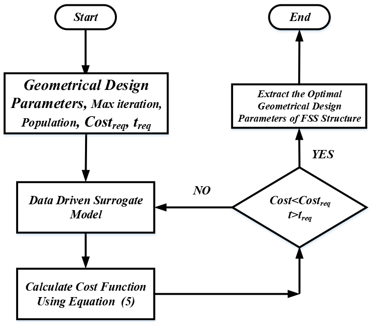
Figure 4: Flow chart of the proposed optimization process.
Furthermore, for justification of the proposed method, the obtained geometrical results are given to 3D EM model in CST and the performance measures of both CST and SVRM surrogate models are compared with each other. As it can be seen from Figure 5, the proposed method has the same performance characteristics as the 3D EM simulator tool.
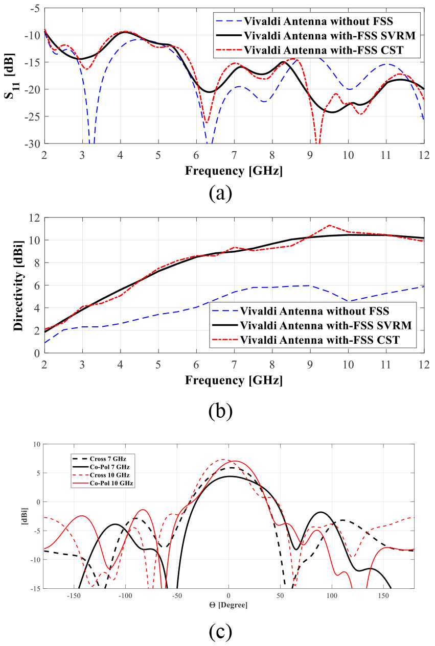
Figure 5: Simulated (a) scattering, (b) directivity, (c) polarization of FSS loaded, antenna designs.
V. FABRICATION AND MEASUREMENT
In this section, for further evaluation of accuracy and stability of the proposed design optimization method, the optimally designed antenna in section IV have been prototyped (Figure 6). The measurement devices (a Network Analyzer with a measurement bandwidth of 9 KHz–13.5 GHz, and LB-8180-NF Broadband Horn Antenna 0.8–18 GHz as reference antenna) available in Microwave Laboratories of Yildiz Technical University had been used.
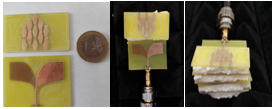
Figure 6: The prototyped FSS-loaded Vivaldi antenna.
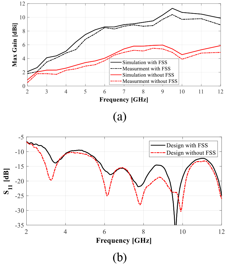
Figure 7: Measured (a) maximum gain, (b) scattering parameters, over the operating band.
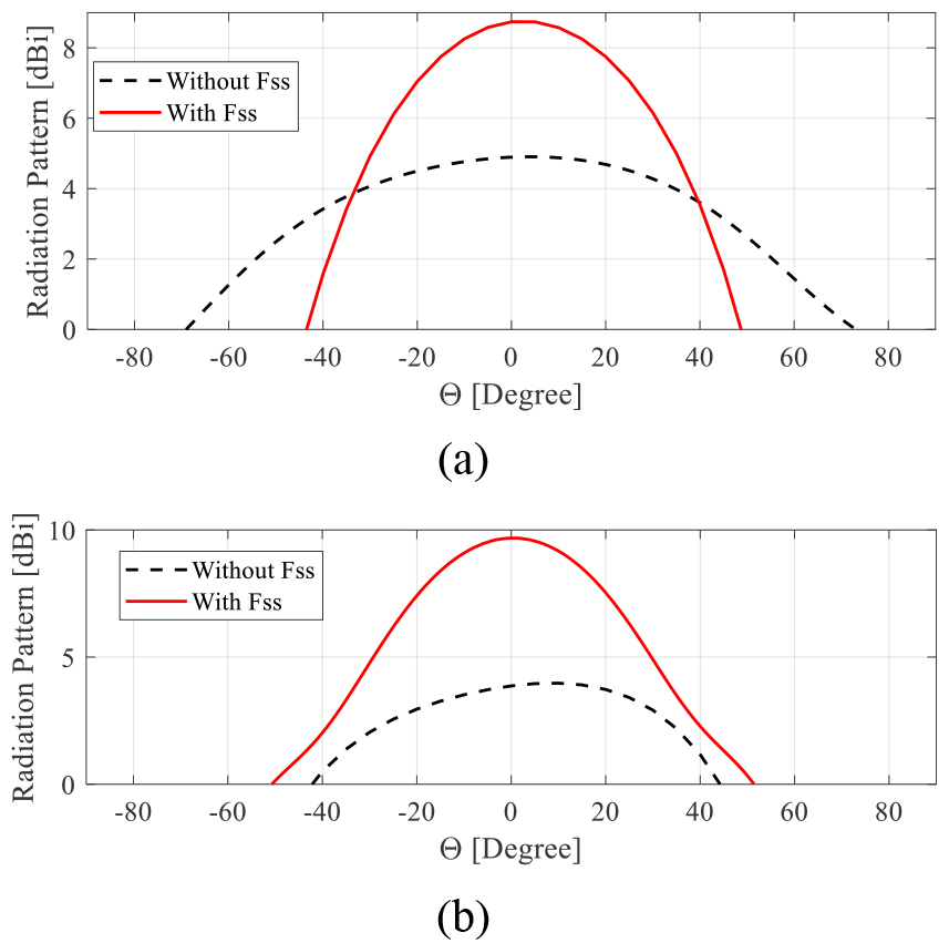
Figure 8: Measured radiation pattern at (a) 7 GHz, (b) 10 GHz.
Table 3: RF performance comparison table
| Work | f | |||
| [GHz] | Gain | |||
| [dBi] | Material | Size [mm] | ||
| Here | 2–12 | 2–11.8 | FR4 Eps:4.4 | 50581.8 |
| 32 | 3.5–16 | 3.5–12.5 | RO4003C Eps: 3.38 | 80.55214.5 |
| 33 | 1–12 | 1.5–5.1 | FR4 Eps: 4.6 | 45401.6 |
| 34 | 0.8–12 | 6.32 | ARLON 600 Eps: 6.15 | 1901281.57 |
| 35 | 1.9–5.5 | 3.6–/4.6 | FR4 Eps: 4.4 | 68.3112.20.8 |
| 36 | 2–18 | 3/12.3 | RO4003C Eps: 3.38 | 1001400.8 |
| 37 | 1.8/5.2 | –/5.5 | FR4 Eps: 4.3 | 80601.6 |
| 38 | 2.9–11.6 | –/3 | Taconic RF-35 Eps: 3.5 | 26260.76 |
| 39 | 2.4/5.2 | 3.6/2.5 | FR4 Eps: 4.3 | 94.51001.6 |
| 40 | 2.9–14.2 | 5–9 | FR4 Eps: 4.3 | 40501.6 |
| 41 | 0.8–3.4 | 2.4–8.1 | FR4 Eps: 4.4 | 1501500508 |
Most of the antenna designs have achieved similar S characteristics. Therefore, in this table S is not included. |
||||
In Figure 7, the measured experimental results of maximum gain, and scattering parameter of the optimally designed FSS-loaded Vivaldi antenna are presented. As it can be seen from the figure, the measured performances of the antenna are in agreement with the simulated results obtained in previous sections. Furthermore, a performance comparison table of the proposed antenna design with the counterpart designs from the literature [32, 33, 34, 35, 36, 37, 38, bib39, 39, 40] is presented in Table 3. As it can be deduced from the performance comparison table, the proposed antenna design achieves high gain, wide operation band performance compared to the counterpart designs in the literature with smaller size and lower cost material for substrate.
VI. CONCLUSION
Herein, design optimization of an FSS-loaded Vivaldi antenna had been achieved using both SVRM-based surrogate model and a metaheuristic optimization algorithm HBMO. By using a multi-layer structured FSS design, the performance of a Vivaldi antenna has been increased without a distortion in the gain and scattering performance of the design. Furthermore, for justification of the proposed method the optimally designed antenna had been prototyped and its performance characteristics are measured. As a result, the measured characteristics are found to be in agreement with the simulated results of the proposed method. The proposed design achieves a maximum gain characteristic of 10 dBi with an operation bandwidth of 2–12 GHz which makes this design a suitable candidate for RADAR applications.
VII. ACKNOWLEDGMENT
We would like to express our special thanks of gratitude to the Aktif Neser Elektronik and DataRobot, for providing researcher licenses for CST and DataRobot. Also, we would like to thank TUBITAK National Observatory for giving partial support under grant number of “119N196.”
REFERENCES
[1] M. Moosazadeh, S. Kharkovsky, J. T. Case, and B. Samali, “Improved radiation characteristics of small antipodal vivaldi antenna for microwave and millimeter-wave imaging applications,” IEEE Antennas Wireless Propag. Lett., vol. 16, pp. 1961-1964, 2017.
[2] F. Zhang, G.-Y. Fang, Y.-C. Ji, H.-J. Ju, and J.-J. Shao, “A novel compact double exponentially tapered slot antenna (DETSA) for GPR applications,” IEEE Antennas Wireless Propag. Lett., vol. 10, pp. 195-198, 2011.
[3] L. Guo, H. Yang, Q. Zhang, and M. Deng, “A compact antipodal tapered slot antenna with artificial material lens and reflector for GPR applications,” IEEE Access, vol. 6, pp. 44244-44251, 2018.
[4] K. Kim, W. R. Scott, and S. Member, “Design of a Resistively loaded Vee dipole for radar applications,” IEEE Trans. Antennas Propag., vol. 53, no. 8, pp. 2525-2532, Aug. 2005.
[5] M. Serhir and D. Lesselier, “Wideband reflector-backed folded bowtie antenna for ground penetrating radar,” IEEE Trans. Antennas Propag., vol. 66, no. 3, pp. 1056-1063, Mar. 2018.
[6] L. Guo, B. Xiao, M. Li, H. Yang, and H. Lin, “A high-gain and frequency tunable bow tie antenna with epsilon-negative metasurface,” J. Electromagn. Waves Appl., vol. 29, no. 5, pp. 693-702, Mar. 2015.
[7] L. Sang, X. Li, T. Chen, and G. Lv, “Analysis and design of tapered slot antenna with high gain for ultra-wideband based on optimisation of the metamaterial unit layout,” IET Microw. Antennas Propag., vol. 11, no. 6, pp. 907-914, May 2017.
[8] A. Z. Hood, T. Karacolak, and E. Topsakal, “A small antipodal vivaldi antenna for ultrawide-band applications,” IEEE Antennas Wireless Propag. Lett., vol. 7, pp. 656-660, 2008.
[9] H. Cheng, H. Yang, Y. Li and Y. Chen, “A compact vivaldi antenna with artificial material lens and sidelobe suppressor for GPR applications,” IEEE Access, vol. 8, pp. 64056-64063, 2020. doi: 10.1109/ACCESS.2020.2984010.
[10] G. Teni, N. Zhang, J. Qiu, and P. Zhang, “Research on a novel miniaturized antipodal Vivaldi,” IEEE Antennas Wireless Propag. Lett., vol. 12, pp. 417-420, 2013.
[11] J. Bourqui, M. Okoniewski, and E. C. Fear, “Balanced antipodal vivaldi antenna with dielectric director for near-field microwave imaging,” IEEE Trans. Antennas Propag., vol. 58, no. 7, pp. 2318-2326, Jul. 2010.
[12] B. Zhou and T. J. Cui, “Directivity enhancement to vivaldi antennas using compactly anisotropic zero-index metamaterials,” IEEE Antennas Wireless Propag. Lett., vol. 10, pp. 326-329, 2011.
[13] S. Kundu, A. Chatterjee, S. K. Jana, and S. K. Parui, “A compact umbrellashaped UWB antenna with gain augmentation using frequency selective surface,” Radioengineering, vol. 27, no. 2, pp. 448-454, Jun. 2018.
[14] E. Erfani, M. Niroo-jazi, and S. Tatu, “A high-gain broadband gradient efractive index metasurface lens antenna,” IEEE Trans. Antennas Propag., vol. 64, no. 5, pp. 1968-1973, May 2016.
[15] H. Cheng, H. Yang, Y. Li and Y. Chen, “A compact vivaldi antenna with artificial material lens and sidelobe suppressor for GPR applications,” IEEE Access, vol. 8, pp. 64056-64063, 2020.
[16] P. Mahouti, “Design optimization of a pattern reconfigurable microstrip antenna using differential evolution and 3D EM simulation‐based neural network model,” Int. J. RF Microw. Comput. Aided Eng., vol. 29, e21796, 2019. https://doi.org/10.1002/mmce.21796.
[17] J. Wang, X. S. Yang, and B. Z. Wang, “Efficient gradient-based optimization of pixel antenna with large-scale connections,” IET Microwaves Ant. Prop., vol. 12, no. 3, pp. 385-389, 2018.
[18] M. Rossi, A. Dierck, H. Rogier, and D. Vande Ginste, “A stochastic framework for the variability analysis of textile antennas,” IEEE Trans. Ant. Prop., vol. 62, no. 16, pp. 6510-6514, 2014.
[19] J. S. Ochoa and A. C. Cangellaris, “Random-space dimensionality reduction for expedient yield estimation of passive microwave structures,” IEEE Trans. Microwave Theory Techn., vol. 61, no. 12, pp. 4313-4321, 2013.
[20] J. Dong, W. Qin, and M. Wang, “Fast multi-objective optimization of multi-parameter antenna structures based on improved BPNN surrogate model,” IEEE Access, vol. 7, pp. 77692-77701, 2019.
[21] J. L. Chávez-Hurtado and J. E. Rayas-Sánchez, “Polynomial-based surrogate modeling of RF and microwave circuits in frequency domain exploiting the multinomial theorem,” IEEE Trans. Microwave Theory Tech., vol. 64, no. 12, pp. 4371-4381, 2016.
[22] N. V. Queipo, R. T. Haftka, W. Shyy, T. Goel, R. Vaidynathan, and P. K. Tucker, “Surrogate-based analysis and optimization,” Progress in Aerospace Sciences, vol. 41, no. 1, pp. 1-28, 2005.
[23] P. Barmuta, F. Ferranti, G. P. Gibiino, A. Lewandowski, and D. M. M. P. Schreurs, “Compact behavioral models of nonlinear active devices using response surface methodology,” IEEE Trans. Microwave Theory and Tech., vol. 63, no. 1, pp. 56-64, 2015.
[24] J. Cai, J. King, C. Yu, J. Liu, and L. Sun, “Support vector regressionbased behavioral modeling technique for RF power transistors,” IEEE Microwave and Wireless Comp. Lett., vol. 28, no. 5, pp. 428-430, 2018.
[25] A. Petrocchi, A. Kaintura, G. Avolio, D. Spina, T. Dhaene, A. Raffo, and D. M. P.-P. Schreurs, “Measurement uncertainty propagation in transistor model parameters via polynomial chaos expansion,” IEEE Microwave Wireless Comp. Lett., vol. 27, no. 6, pp. 572-574, 2017.
[26] J. E. Rayas-Sanchez and V. Gutierrez-Ayala, “EM-based statistical analysis and yield estimation using linear-input and neural-output space mapping,” IEEE MTT-S Int. Microwave Symp. Digest (IMS), pp. 1597-1600, 2006.
[27] P. Mahouti, A. Kızılay, O. Tari, A. Belen, M. A. Belen, “Design optimization of ultra wide band vivaldi antenna using artificial intelligence,” International Applied Computational Electromagnetics Society (ACES) Symposium, pp. 1-4, 2021. doi: 10.1109/ACES53325.2021.00164.
[28] X. Zhang, Y. Chen, M. Tian, J. Liu, and H. Liu, “A compact wide-band antipodal Vivaldi antenna design,” Int. J. RF Microw. Comput. Aided Eng., vol. 29, e21598, 2019. https://doi.org/10.1002/mmce.21598.
[29] F. Güneş, İ. Ö. Evranos, M. A. Belen, P. Mahouti, and M. Palandöken, “A compact triband antipodal vivaldi antenna with frequency selective surface inspired director for IoT/WLAN applications,” Wireless Netw., vol. 27, pp. 3195-3205, 2021.
[30] F. Güneş, S. Demirel, and P. Mahouti, “A simple and efficient honey bee mating optimization approach to performance characterization of a microwave transistor for the maximum power delivery and required noise,” Int. J. Numer. Model., vol. 29, pp. 4-20, 2016.
[31] F. Güneş, S. Demirel, and P. Mahouti, “Design of a front-end amplifier for the maximum power delivery and required noise by HBMO with support vector microstrip model,” Radioengineering, vol. 23, no. 1, pp. 134-143, 2014.
[32] X. Li, G. Liu, Y. Zhang, L. Sang, G. Lv, “A compact multi-layer phase correcting lens to improve directive radiation of Vivaldi antenna,” Int. J. RF Microw. Comput. Aided Eng., 2017.
[33] D. M. Elsheakh, E. A. Abdallah, “Ultrawideband vivaldi antenna for DVB-T, WLAN, and WiMAX applications,” International Journal of Antennas and Propagation, vol. 8, pp. 1-7, 2014.
[34] J. Schneider, M. Mrnka, J. Gamec, M. Gamcova, Z. Raida, “Vivaldi antenna for RF energy harvesting,” Radioengineering, vol. 25, no. 4, pp. 666-671, 2016.
[35] R. Bulgaroni, W. M. Torres, H. X. de Araujo, I. R. S. Casella, C. E. Capovilla, “Low-cost quad-band dual antipodal Vivaldi antenna using microstrip to CPS transition,” Microw. Opt. Technol. Lett., vol. 60, pp. 2315-2320, 2018.
[36] A. S. Arezoomand, R. A Sadeghzadeh, M. N. Moghadasi, “Investigation and improvement of the phase‐center characteristics of VIVALDI’s antenna for UWB applications,” Microw. Opt. Tech. Lett., vol. 58, no. 6, pp. 1275-1281, 2016.
[37] R. Natarajan , M. Kanagasabai, M. Gulam, N. Alsath, “Dual mode antipodal Vivaldi antenna,” in IET Microwaves, Antennas & Propagation, vol. 10, no. 15, pp. 1643-1647, 2016.
[38] Z. Li, C. Yin, X. Zhu, “Compact UWB MIMO vivaldi antenna with dual band-notched characteristics,” in IEEE Access, vol. 7, pp. 38696-38701, 2019.
[39] H. Zhu, X. Li, L. Yao, and J. Xiao, “A novel dielectric loaded vivaldi antenna with improved radiation characteristics for UWB application” Applied Computational Electromagnetics Society Journal, vol. 33, no. 4, pp. 394-399, 2018.
[40] Y. Zhu, D. Su, W. Xie, Z. Liu, and K. Zuo, “Design of a novel miniaturized vivaldi antenna with loading resistance for ultra wideband (UWB) applications” Applied Computational Electromagnetics Society Journal, vol. 32, no. 10, pp. 895-900, 2017.
BIOGRAPHIES

Peyman Mahoutireceived his M. Sc. And Ph.D. degree in Electronics and Communication Engineering from the Yıldız Technical University, Turkey, in 2013 and 2016, Respectivly. He is currently an Associated Professor with the Department of Electronic and Communication, Istanbul University - Cerrahpasa, Turkey. The main research areas are analytical and numerical modelling of microwave devices, optimization techniques for microwave stages, and application of artificial intelligence-based algorithms. His research interests include analytical and numerical modelling of microwave and antenna structures, surrogate-based optimization, and application of artificial intelligence algorithms.

Ahmet Kizilaywas born in Istanbul, Turkey, in 1969. He received B.Sc. degree in Electronics and Communications Engineering from Yildiz University in 1990, M.Sc. and Ph.D. degrees in Electrical Engineering from Michigan State University in 1994 and 2000, respectively.
In July 2001, he joined the Department of Electronics and Communications Engineering at Yildiz Technical University, where he is currently working as Professor. His main research interests include time domain electromagnetic scattering, electromagnetic wave theory, and fiber optics.

Özlem Tarireceived her B.Sc., M.Sc. and Ph.D. in Physics Engineering from the Istanbul Technical University (ITU). She was the recipient of the Universidad Carlos III de Madrid Research Fellowship award before accepting her position at Istanbul Arel University in 2010. Her research areas are the phase transitions and phase diagram of some physical systems, Multi-Objective Optimization problems and development of Meta-Heuristic Optimization Algorithms.

Aysu Belenreceived his Ph.D. degree in Electronics and Communication Engineering from the Yıldız Technical University in 2021. Currently, she is a Lecturer in İskenderun Technical University. Her main research areas are optimization of microwave circuits, circuits, device modeling, and computer aided circuit design and microwave amplifiers.

Mehmet Ali Belenreceived his Ph.D degree in Electronics and Communication engineering from the Yıldız Technical University in 2016. He is currently an Associated Prof. in İskenderun Technical University. His current activities include teaching and researching Electromagnetics and Microwaves along with developing Additive Manufacturing 3D Printed Microwave Components for Rapid Prototyping. His current research interests are in the areas of multivariable network theory, device modeling, computer aided microwave circuit design, monolithic microwave integrated circuits, and antenna arrays, active/passive microwave components especially in the field of metamaterial- based antennas and microwave filters.

Alper Çalşkanreceived his Ph.D. degree in Electronics and Communication Engineering from the Yıldız Technical University in 2019. The main research areas are optimization of microwave circuits, broadband matching circuits, device modeling, and computer aided circuit design, microwave amplifiers.
ACES JOURNAL, Vol. 36, No. 12, 1594–1601.
doi: 10.13052/2021.ACES.J.361211
© 2021 River Publishers