A Novel Design of Microwave Absorbers Based on Multilayered Composite Materials for Reduction of Radar Cross Section
Hong Qin Zheng, Yi Tao Huang, and Mei Song Tong
1Department of Electronic Science and Technology, Tongji University, Shanghai 201804, China
mstong@tongji.edu.cn
Submitted On: September 17, 2021; Accepted On: April 3, 2022
Abstract
Reduction of radar cross section (RCS) for targets can be achieved by different approaches and coating absorbing materials at the surfaces of targets is one of widely used methods because of its flexibility and good effect. In the work, we put forward a novel method of reducing the RCS based on the design of multilayer composite absorbing materials. The transmission line theory and particle swarm optimization (PSO) are used to guide the design and analysis, and two kinds of designs, i.e., Type IV and Type VII, are selected finally. Simulation experiments show that the designs are insensitive to the incident angles and polarizations of incident EM wave, which is required for being coated at the surfaces of real objects. Also, the designed absorbing materials are very thin and have an ultra-wide frequency band. The bandwidth of Type-IV design can reach GHz, ranging from to GHz, while Type-VII design can cover the frequency range from to GHz, which represents the major part of radar’s frequency range. The designed absorbing materials are coated at the surface of a perfectly-electric-conducting (PEC) cylinder to validate the effectiveness of the materials, and good results have been obtained.
Keywords: Microwave absorber, absorbing media, radar cross section, transmission line theory, particle swarm optimization.
I. INTRODUCTION
Radar cross section (RCS) is a measure for the strength of electromagnetic (EM) fields scattered by targets and reducing the RCS as much as possible is the basic requirement for designing stealth targets [1]. With the significant development of radar techniques since World War II, reducing the RCS of targets has become a passive and indispensable technique for reducing the detectability of targets [2] and has been eagerly needed in military applications or even in some civilian applications [3]. Generally, there are four categories of techniques for reducing the RCS, i.e., design of geometric shape, coating of microwave absorbing material, passive cancelation, and active cancelation [4]. Each method has its advantages and disadvantages. Compared with the other three methods, coating the absorbing materials could be the most important because it is flexible, cost-effective, of good performance, and has been widely applied in the RCS reduction for the targets like airplanes, ships, missiles, etc., or even used in the interference shielding of some targets [5–7].
The reduction of RCS by covering appropriate absorbing materials is a very hot research topic and many researchers have been dedicated to working on the topic for a long time. The earliest microwave absorber can date back to the early 1940s when Winfield Salisbury invented the Salisbury screen [8]. After that, various microwave absorbers, such as the Jaumann screen, the Dallenbach layer, the frequency selective surface, etc., were proposed and have been developed for many years [9–13]. In recent years, the metamaterial as a novel absorbing material has caught up a wide attention [14]. Although the metamaterial has the property that can greatly extend the parameter space accessible with natural materials, it has some obvious drawbacks in practical applications. The metamaterial absorbers usually have a narrow bandwidth [15] although they could be insensitive to the incident angles and polarizations of incident waves which is also very desirable. He and Jiang proposed a kind of metamaterial absorber that had shown a wideband absorption, but it still cannot cover a wider frequency range which most of the radars are using [16]. Also, some metamaterial absorbers are actually sensitive to the incident angles and polarizations of incident waves, greatly reducing theirapplicability.
Compared with the metamaterial, some composite materials have shown a better performance, i.e., they can not only cover a much wider frequency range but also be insensitive to the incident angles and polarizations [17]. Thanks to the significant progress of material science, it has become feasible to synthesize composite materials that have much lower or higher EM parameters which allow to extensively adjust the performance of materials [18]. Yuan et al. proposed an ultra-thin broadband composite absorbing material which has an operating bandwidth ranging from to GHz [19]. Ali et al. presented the design of novel and lightweight microwave absorbers, which also exhibited a broad bandwidth of 3.74 GHz [20]. Ling et al. designed a broadband absorbing material whose effective absorption bandwidth reaches GHz and total thickness is only mm [21].
All designs for the microwave absorbers in the above are assumed to work on an infinitely large plate and their EM performance is also obtained under this assumption. However, real objects like airplanes have curvilinear surfaces that could include finite plates, corners, and other-shaped parts in various sizes. As a result, the absorbers are required to possess a stable performance when incident waves are of different incident angles and polarizations. Some composite materials like carbonyl iron powders (CIPs) [22] have been proven to be insensitive to the incident angles and polarizations so that they can be used as such absorbers [23]. The existing materials have the problems of narrow operation bandwidth. Meanwhile, the relative bandwidths of the absorbing materials which are suitable for the detection frequency band of the radar are small. In the operation frequency band, the existing materials also have the disadvantages of low absorptivity and angle sensitivity and the EM parameters of which are instable neither. The existing design methods often determine the final structure through the analysis of EM parameters or repeated simulation. This method costs a lot of time and may not necessarily obtain the best iterative convergence result under thiscondition.
In this work, we propose a novel method to design the absorbers for reducing the RCS of some objects. Since most of the radar systems are working at the frequency range from to GHz, we try to design the absorbers that can cover most of radar’s frequency range, i.e., from to GHz. We apply the transmission line theory (TLT) and particle swarm optimization (PSO) to the design of multilayered absorbers which are composed of two types of CIP composite materials. We then choose two representative designs to investigate their performance on the reduction of RCS under the different incident angles and polarizations of incident waves. Based on the simulation experiments, we can find the best design of absorbers that are most insensitive to the incident angles and polarizations. Finally, the designed absorbers are coated on the surface of a perfectly-electric-conducting (PEC) cylinder and we demonstrate that the designed absorbers can perform well for real objects.
II. MICROWAVE ABSORBING MATERIALS
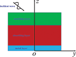
Microwave absorbing materials are used to coat the surface of targets in the reduction of RCS. Compered with single-layer absorbers, multilayered absorbers are more flexible and can achieve better performance, including wider bandwidth and smaller thickness [24]. As shown in Figure 1, a multilayered absorber usually consists of the matching layer and the absorbing layer [25]. The matching layer, which is on the top of the absorber, helps couple the impedance of the free space with the impedance of the absorber. On the other hand, the absorbing layer, which is on the bottom of the absorber, absorbs most of EM energies.
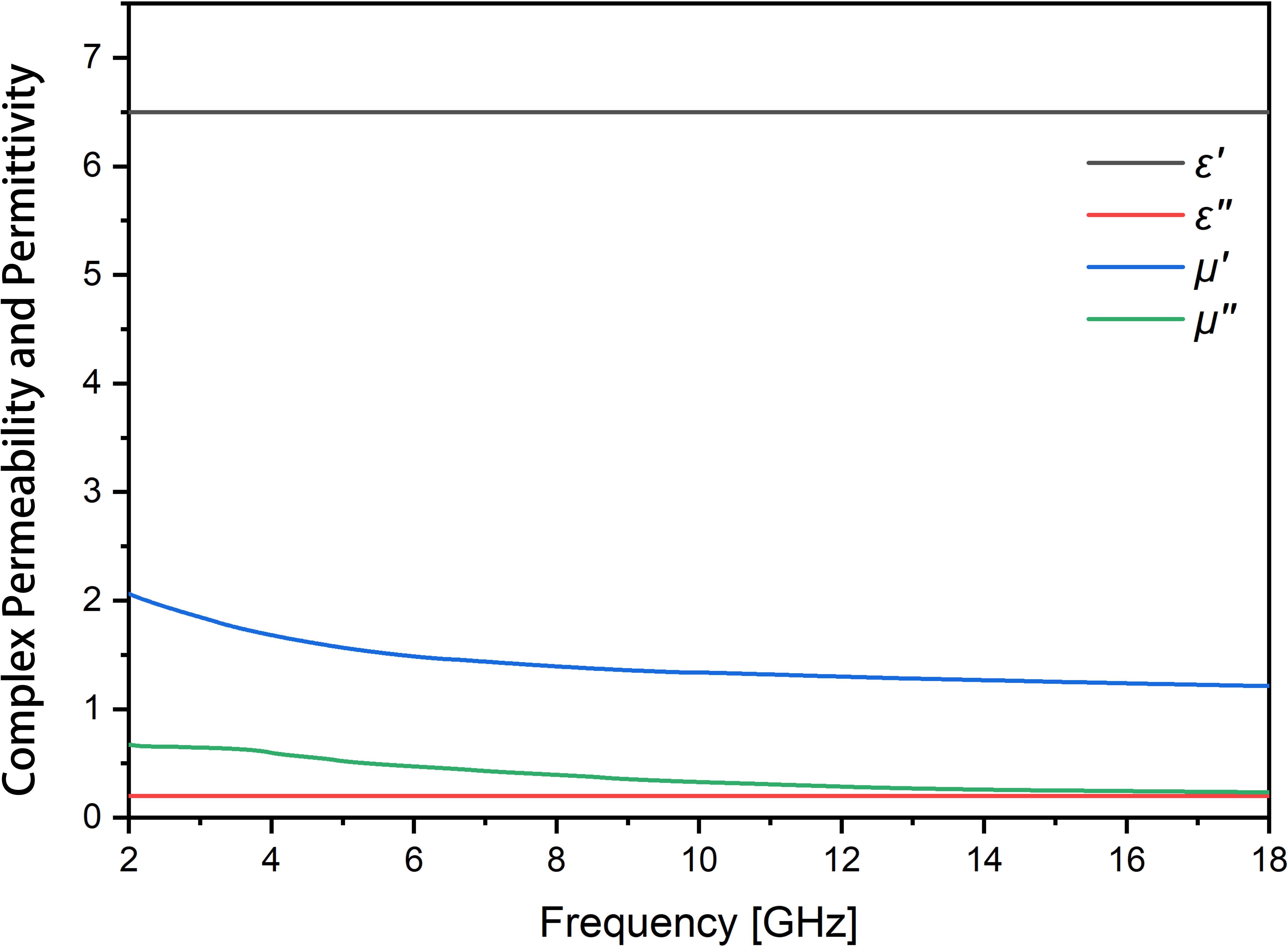
Figure 1: Structure of a multilayered absorber.
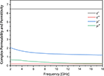
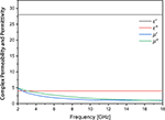
The used materials are essential in the design of absorbers since the performance of absorbers mainly depends upon the performance of used materials. Each layer consists of different materials so that different designs of absorber with different performances can be obtained. Usually, there are three types of material in the design of microwave absorbers, i.e., dielectric material, magnetic material, and composite material [26]. In this paper, two types of composite materials with different proportions of CIPs are used since the CIPs have exhibited a very strong absorbing capability for EM energies [22]. The composite material with CIP is used to build the matching layer, and the composite material with CIP is used to construct the absorbing layer. Hereinafter, we will use to represent the composite material with 10 CIP and use to indicate the composite material with 35 CIP. The complex permittivity and complex permeability of the two composite materials are frequency-dependent and their relationships are shown in Figures 2 and 3, respectively.
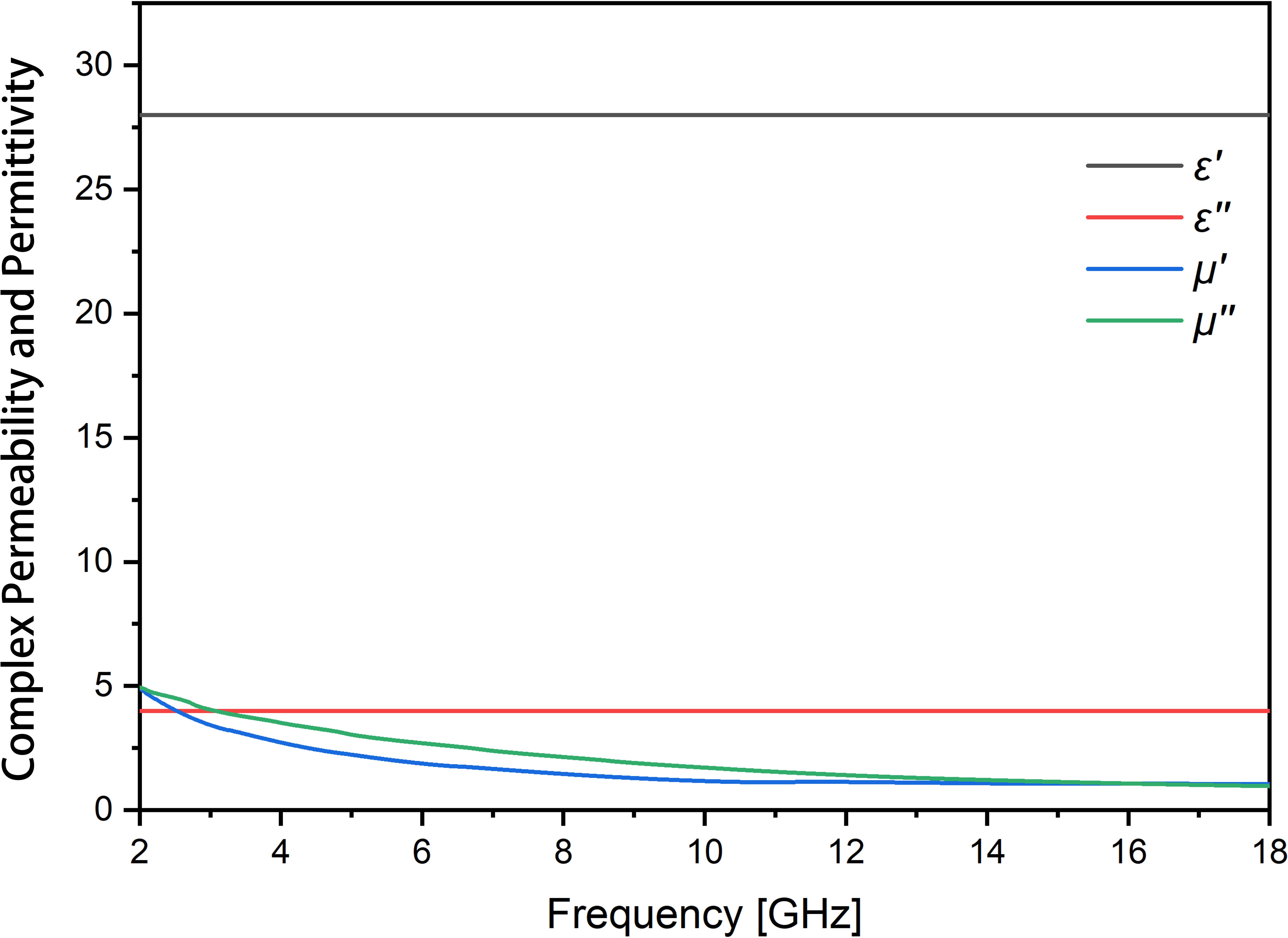
Figure 2: Permittivity and permeability of composite material with 10 CIP. Prime denotes the real part while double prime denotes the imaginary part.
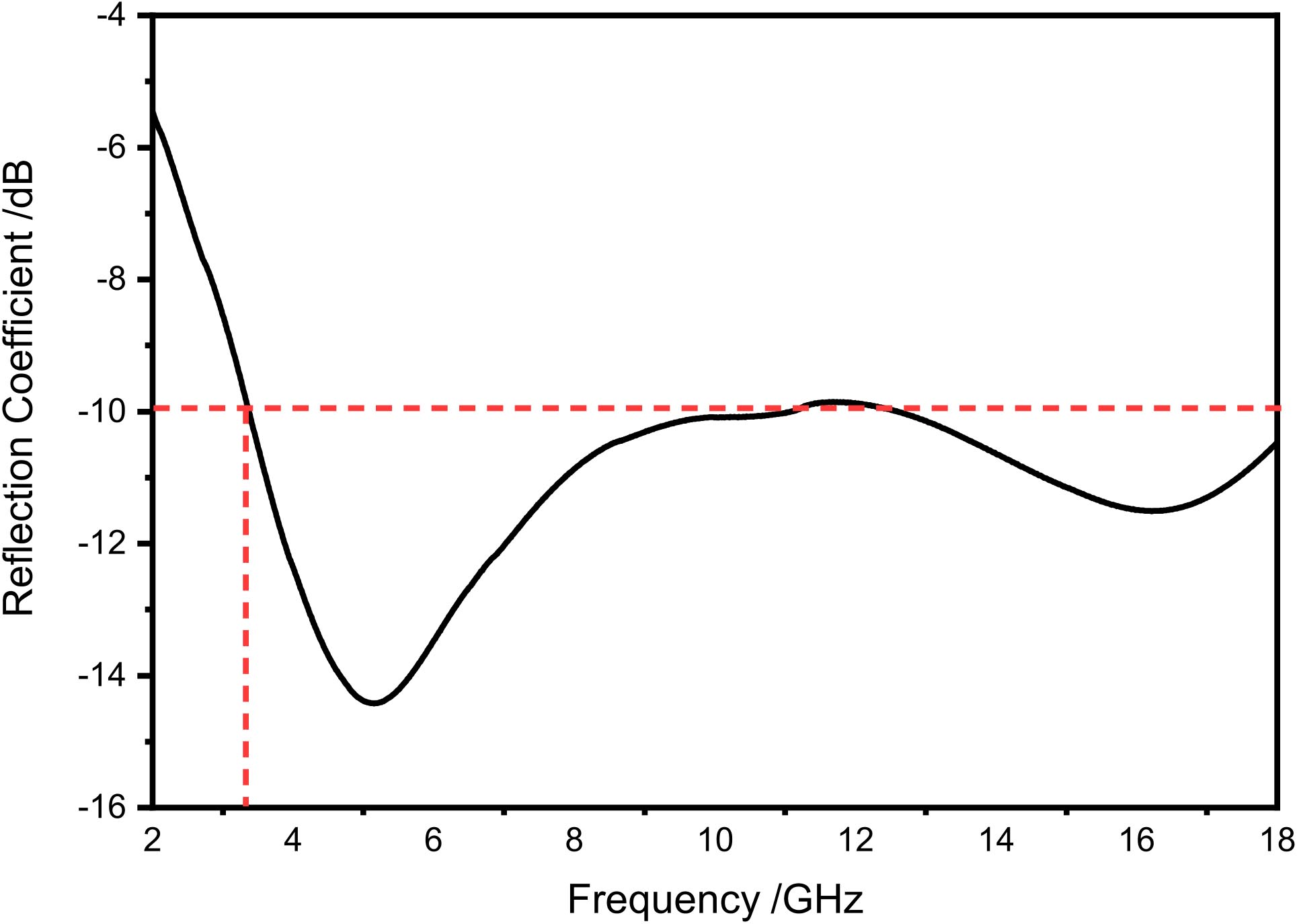
Figure 3: Permittivity and permeability of composite material with 35 CIP. Prime denotes the real part while double prime denotes the imaginary part.
From the figures, we can see that the complex permittivity and complex permeability (referring to the magnitudes of their real and imaginary parts) of are relatively low in the frequency range from to GHz. Also, the complex permittivity of is almost constant in the above frequency range and the complex permeability varies with the frequency very slowly. As a result, it is possible that the impedance of a layer composed of is close to the impedance of free space in the above frequency range. Compared to , the material owns a higher complex permittivity and complex permeability. Moreover, the magnitude of complex permittivity is stable and the magnitude of complex permeability decreases slightly. This feature leads to that has a good absorption and poor impedance matching while has an opposite behavior.
III. DESIGN OF MULTILAYERED ABSORBERS
The design of absorbers requires an efficient and accurate analysis or evaluation for their performance. Full-wave EM simulation is a good way to do that, but it consumes much time and resources. Compared to the former approach, the TLT can also be used to analyze but requires much less time and resources. Usually, a planar multilayered absorber can be represented by a transmission-line model so that we can apply the TLT to analyze the behavior of multilayered absorbers. In the analysis, the reflection coefficient of absorbers can be used to evaluate the performance if the input impedance is available. The input impedance can be calculated by using the TLT [27], i.e.,
| (1) |
where
| (2) | |
| (3) | |
| (4) |
Also, , , , , , and denote the thickness, frequency, speed of light, complex permittivity, complex permeability, and intrinsic impedance of the th layer (), respectively. In addition, and are the permittivity and permeability of free space, is the wave impedance of the th layer, and is the total number of layers. Based on the input impedance, the overall reflection coefficient of the multilayered absorber at an air-absorber interface is given by
| (5) |
If we choose , i.e., design a two-layer absorber, then the input impedance can be simplified as
| (6) |
where
| (7) |
and the overall reflection coefficient is
| (8) |
In the above, is the wave impedance at the surface of the first layer and is the wave impedance at the second layer. With the reflection coefficient, we can calculate the absorption of the incident EM wave normal to the planar multilayered absorber.
Based on the above method of evaluating the performance of absorbers, we can then design desirable multilayered absorbers. How to determine the number of layers, type of materials, and thickness of each layer is the key in the design, and optimization algorithms can be used to efficiently select those parameters with a low cost [28]. Compared with other optimization methods, the PSO is an efficient method that can be easily used in the design of absorbers [29]. The PSO was inspired by a flying swarm of birds searching for food and we use it to seek optimal values for the thickness of each layer and the number of layers [30]. In order to obtain the optimal result, we should take the total thickness, bandwidth, and reflection peak together into consideration. Therefore, the cost function to be optimized can be set as [31, 32]
| (9) |
where is the minimum of reflection coefficient, is the thickness of th layer, is the bandwidth of the absorber, is the average of reflection coefficient, and is the weight of each term. Also, represents the total thickness of the multilayered absorber. Selecting the appropriate weight for each term, we can get the optimal values for those parameters by minimizing the cost function.
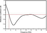
Considering the simplest case, namely, the number of layers is chosen as , we can get a planar design. The two-layer absorber is composed of the matching layer and absorbing layer. The matching layer on the top of the absorber consists of the material while the absorbing layer on the bottom of the absorber consists of the material . After using the PSO to minimize the above cost function, we can obtain the optimal value mm for the matching layer and mm for the absorbing layer, respectively, and the total thickness of the absorber is then mm. With the optimal thickness of each layer, the reflection coefficient of the two-layer absorber can be calculated and is shown in Figure 4.
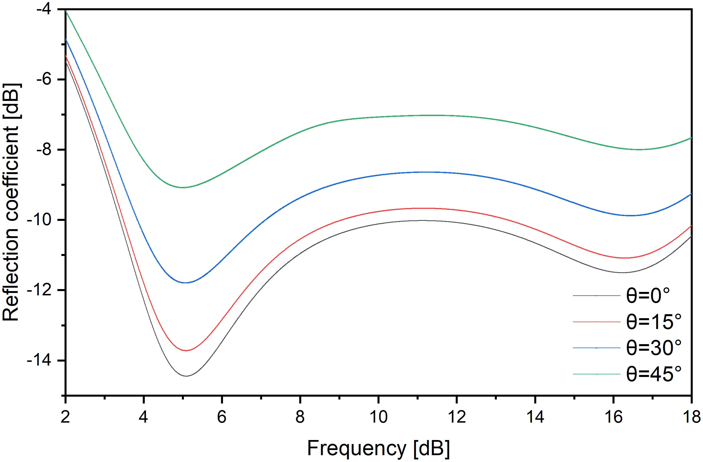
Figure 4: Reflection coefficient of a two-layer absorber.
As shown in Figure 4, the absorber can cover most of the frequency range from to GHz. Furthermore, the bandwidth of the absorber is GHz ranging from to GHz. The minimum return loss appears at GHz and the value is dB. These data demonstrate that the two-layer absorber has a good performance.
If we increase or decrease the number of layers, the behavior of the absorber could significantly change. When a multilayer absorber is designed, the performance of absorber will vary in terms of the thickness of each layer, type of materials, and number of layers. Based on the design of two-layer absorber, we change the number of layers from to and the thickness of each layer is different in different cases. Through the optimization by the PSO, we obtain seven multilayered designs and the final results are shown in Table 1.
Table 1: Multilayered absorber design (unit: mm)
| Absorber | Layer I | Layer II | Layer III | Layer IV | Layer V |
| Type I | S1 | - | - | - | - |
| 3.00 | - | - | - | - | |
| Type II | S2 | - | - | - | - |
| 3.00 | - | - | - | - | |
| Type III | S1 | S2 | - | - | - |
| 0.64 | 0.30 | - | - | - | |
| Type IV | S2 | S1 | - | - | - |
| 0.87 | 2.13 | - | - | - | |
| Type V | S2 | air gap | S1 | - | - |
| 0.01 | 0.87 | 2.20 | - | - | |
| Type VI | air gap | S2 | air gap | S1 | - |
| 0.01 | 1.14 | 1.16 | 1.03 | - | |
| Type VII | S2 | air gap | S2 | air gap | S1 |
| 1.19 | 1.14 | 0.33 | 1.47 | 1.06 |
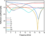
As we can see from Table 1. the seven designs have different values for the number of layers, type of materials, and thickness of each layer, and their performances vary greatly in the working frequency range of GHz, as shown in Figure 5.
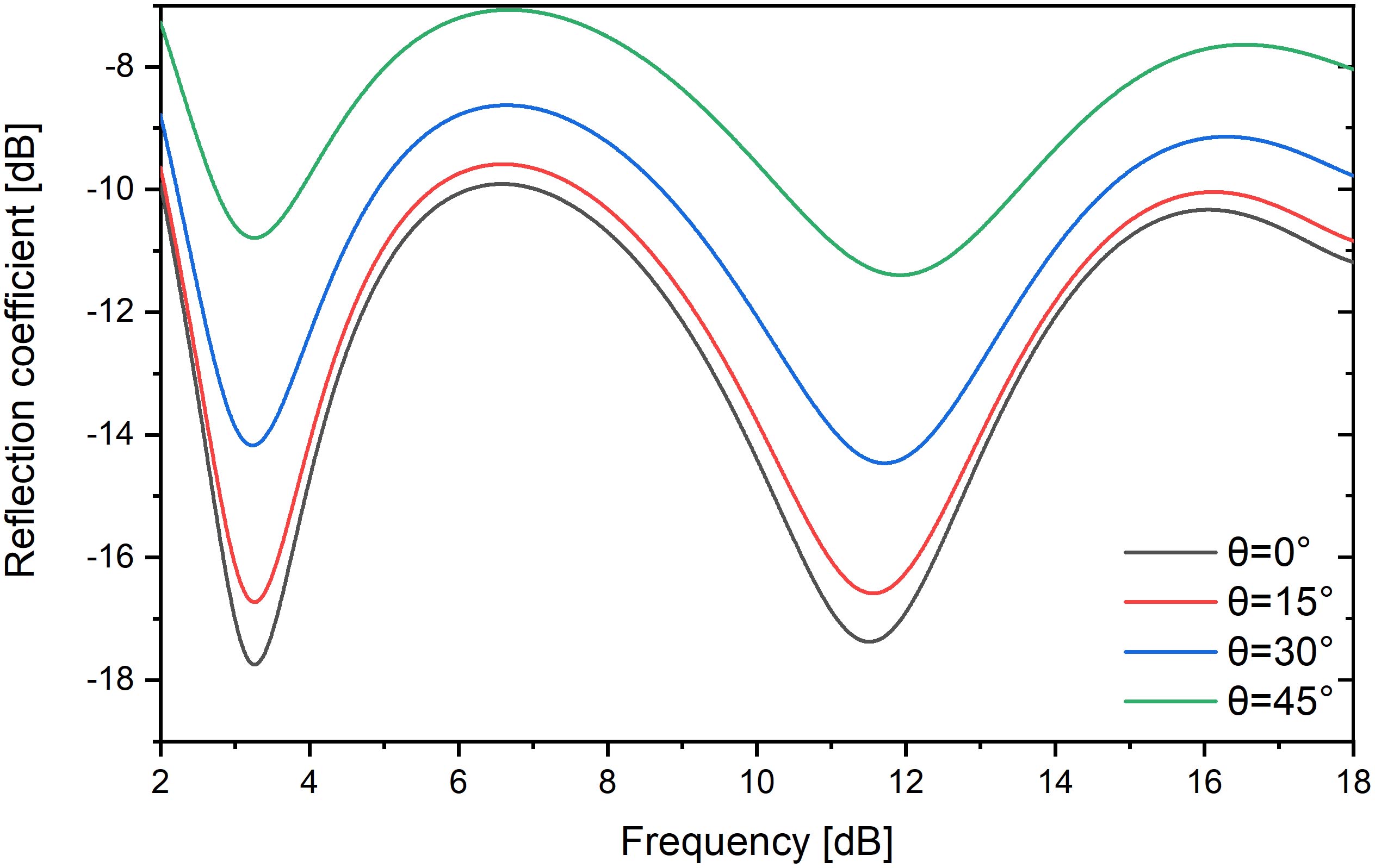
Figure 5: Reflection coefficients of multilayered absorbers.
From Table 1 and Figure 5, we can see that the designs of Type I and Type II are both single-layer absorbers with a narrow bandwidth. The reflection peak of Type-I design cannot reach a reflection peak of dB when the thickness is mm, and Type-II design only covers a very narrow frequency band with a thickness of mm. Thus, a single-layer absorber cannot well absorb the EM energy at most frequencies and a multilayered design is needed to increase both the reflection peak and bandwidth. Type-III design consists of the material as the absorbing layer and the material as the matching layer. As shown in the Table 1 and Figure 5, this design presents a good reflection peak with about dB and covers a wider frequency band from to GHz. After exchanging the materials of the matching layer and the absorbing layer, Type-IV design shows a lower reflection peak with about dB, but its bandwidth increases to nearly GHz. After adding several air gaps to the design, we can get three different planar designs which are labeled as Type V, Type VI, and Type VII, respectively. Type-V design is a three-layer absorber composed of the material , an air gap, and the material . Its total thickness is mm and bandwidth is also nearly GHz. The total thickness of Type-VI design is mm and its reflection peak reaches dB. However, Type-VI design cannot give a good absorption performance at lower frequencies. In addition, Type-VII design is a five-layer absorber which consists of the material , two air gaps, and the material . Its absorption performance is improved because its absorption can cover all frequencies in the bandwidth of GHz. Moreover, its total thickness is mm which is still small, and its minimum reflection peak achieves dB. From the above results, it is clear that increasing total thickness by increasing the number of layers can significantly improve the performance of absorbers, but the thickness is still small enough when the wisely chosen composite materials are used.
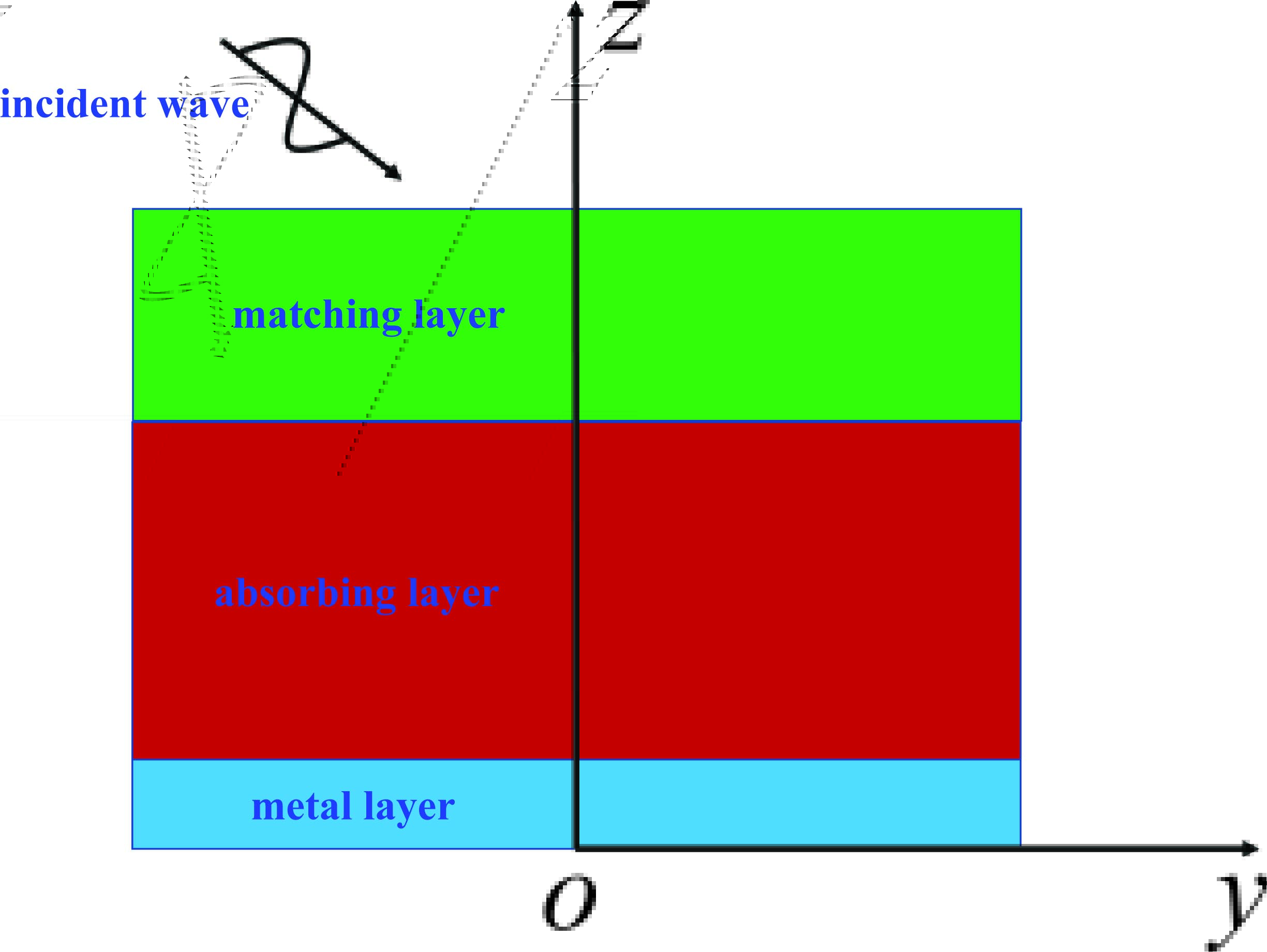
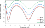
Figure 6: Reflection coefficient of Type-IV design at four different incident angles.
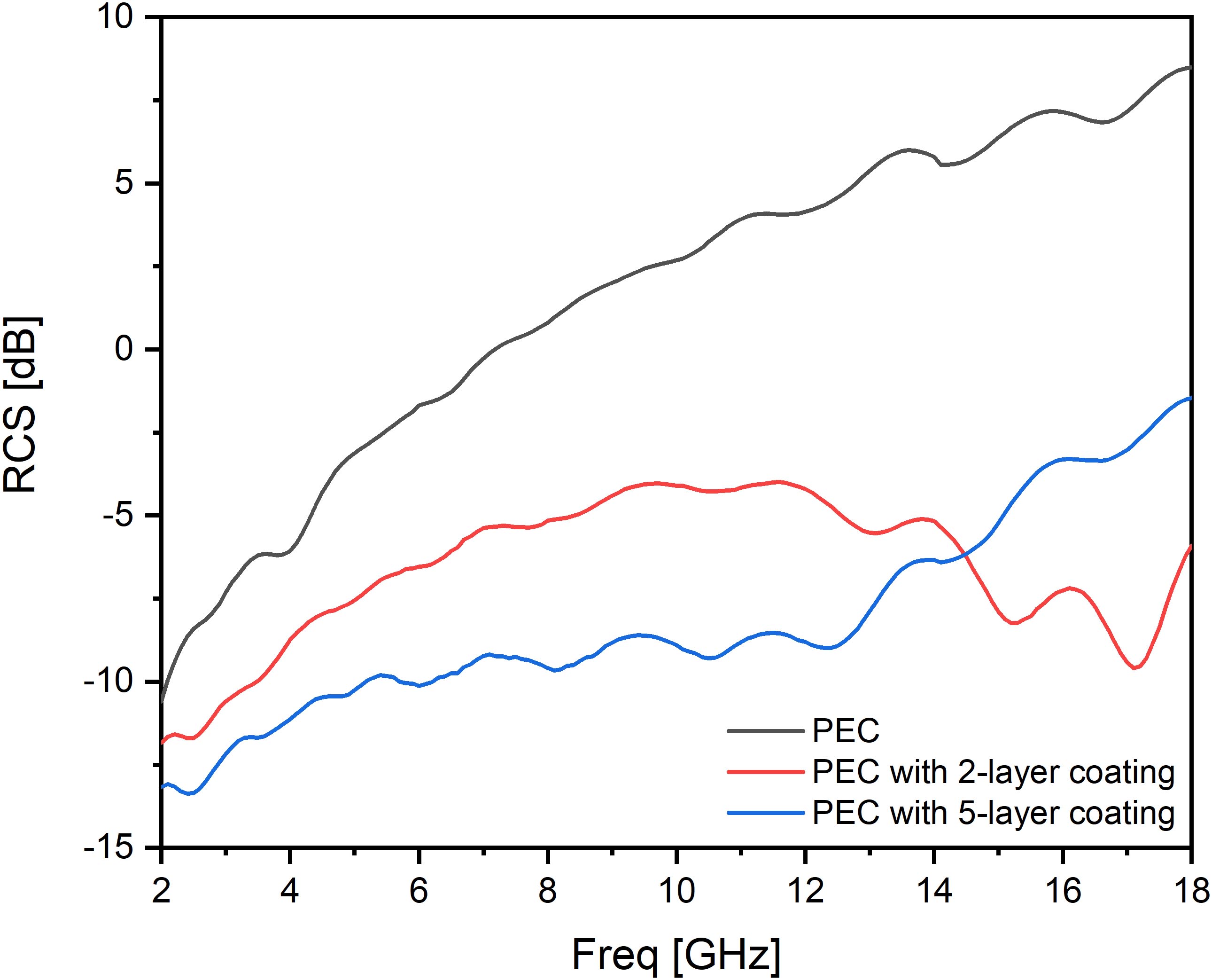
Figure 7: Reflection coefficient of Type-VII design at four different incident angles.
IV. DESIGN OF ABSORBERS FOR COATING REAL OBJECTS
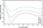
The above designs assume that the surfaces of absorbers are planar and infinitely large, but the absorbers need to cover the surfaces of arbitrarily shaped objects rather than infinitely large planar surfaces. Thus, it is required that the designed absorbers should not only have a wide bandwidth but also be insensitive to the incident angles of incident waves. We investigate how the incident angles impact the performances of absorbers by choosing Type-IV and Type-VII designs from the previous designs as examples and setting up four different incident angles from to with an interval of . With the four different incident angles, we calculate the reflection coefficients for Type-IV and Type-VII designs and the results are shown in Figures 7 and 7, respectively. Type IV is a two-layer planar design whose thicknesses of the matching layer and absorbing layer are and mm, respectively. The planar design can cover the frequency range from to GHz with a bandwidth of nearly GHz. The minimum reflection loss appears at GHz with a value of dB. Additionally, the total thickness of the design is only mm, which is very thin. As shown in Figure 7, there are four absorption rates that are similar to each other but in different positions. The reflection coefficient becomes smaller at a certain frequency when the incident angle increases from to . Moreover, similar results can be seen when the incident angle is and , which means that the design can still give an optimal performance if the range of incident angle is not very large. Even though the incident angle increases to , all the four cases have shown a good performance and their reflection coefficients are below dB for most frequencies from to GHz.
Type VII is a five-layer planar design, which consists of the material , an air gap, the material , an air gap, and the material in the order from the bottom to the top. In addition, thicknesses of five layers from the bottom to the top are , , , , and mm, respectively. The absorber can overcome the drawback of Type-IV design, i.e., the poor performance at lower frequencies. It can achieve a broadband from to GHz and a minimum reflection loss at GHz, whose value is dB. Obviously, Type-VII design gives a better performance as shown in Figure 7. This clearly demonstrates that the smaller the incident angle is, the lower the absorption rate of Type-VII design is. In addition, the four curves in Figure 7 resemble each other but have different -axis positions. Furthermore, the reflection coefficients of all the four cases are not more than dB at the frequency range from to GHz.
Compared to the Type-IV design, the Type-VII design has better results for all the four cases. Type-VII design can still produce excellent results for all the four cases even at lower frequencies, and its minimum reflection loss is also smaller than that of Type-IV design. Nevertheless, both Type-IV and Type-VII designs are insensitive to the incident angles; so they can both perform well when coated at other objects with different shapes.
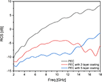
In order to validate the performances of designed absorbers, we coat the absorbers on the surface of a PEC cylinder and calculate the monostatic RCS for the cylinder with and without the coating. The PEC cylinder has a height of mm and a cross-sectional radius of mm, which is equivalent to two wavelengths at the frequency of GHz. We select three incident angles to verify the absorbing capacity of two types of coating materials. When the incident wave perpendicularly incidents to the upper circular surface of the cylinder and its polarization is horizontally polarized, the results of monostatic RCS of the cylinder with Type-IV coating or Type-VII coating or without coating are shown in Figure 8.
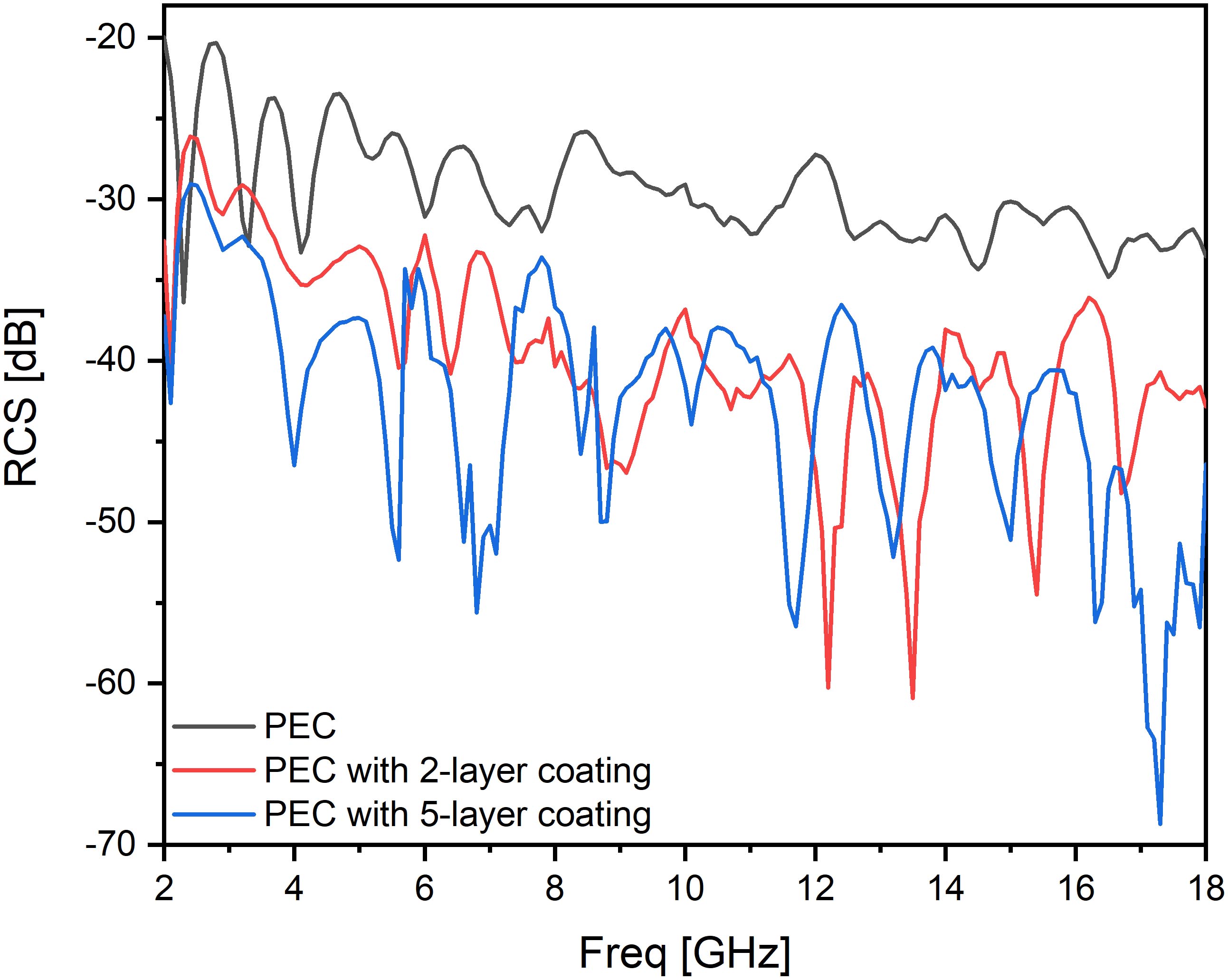
Figure 8: Comparison of monostatic RCS solutions for the PEC cylinder without and with the coating tested by the perpendicularly incident wave.
Figure 8 shows that the performance of two kinds of coating is obviously better than that without the coating and the performance of the Type-IV coating is better than that of the Type-VII coating, especially at the lower frequencies from to nearly GHz. From to GHz, the performance of Type-IV is better than Type-VII. The Type-IV coating can help to reduce the RCS in minimum dB at GHz and in maximum dB at GHz. The Type-VII coating can help to reduce the RCS in minimum dB at GHz and in maximum dB at GHz. The RCS of the PEC cylinder without the coating increases from to dB as the frequency increases. In addition, for the Type-IV coating, its RCS reduction becomes larger as the frequency increasing in most part of the operation band. While with the coating of Type-VII, its RCS reduction becomes larger from to GHz and then maintains a large reduction of nearly dB from to GHz.
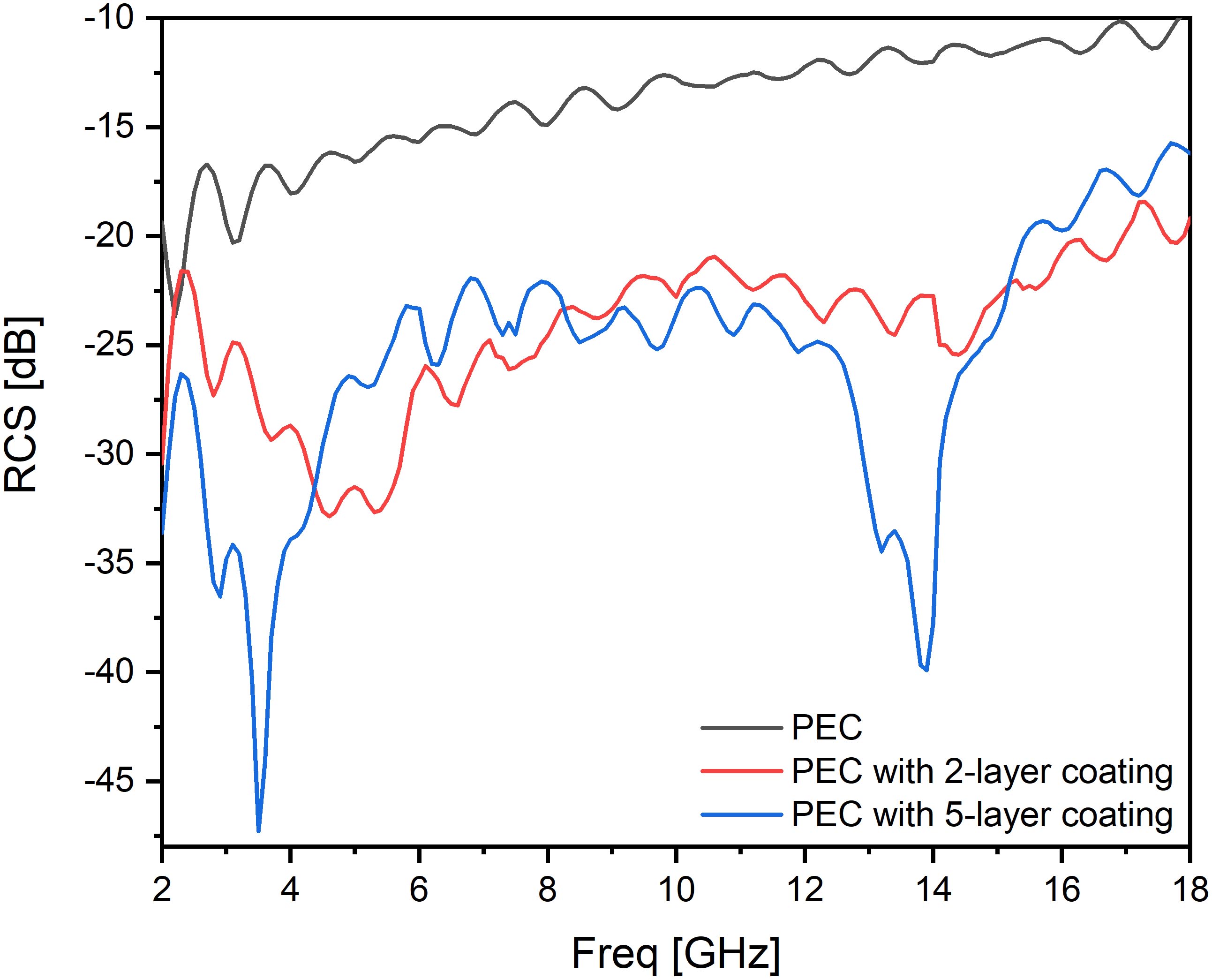
Figure 9: Comparison of monostatic RCS solutions for the PEC cylinder without and with the coating at the incident angle of to the upper circular surface of the cylinder.
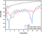
When the incident wave which is horizontally polarized incidents with an angle of to the upper circular surface of the cylinder, the results of RCS of the cylinder with Type-IV coating or Type-VII coating or without coating are shown in Figure 9. The RCS of the PEC cylinder without the coating is below dB at low frequency and decreases to dB as the frequency increases to GHz. Both of the coatings have the ability to reduce the RCS more than dB at most of the frequency band. At a huge part of the frequency band, the reduction of Type-VII coating is higher than that of Type-IV coating, especially at the lower frequencies and higher frequencies.
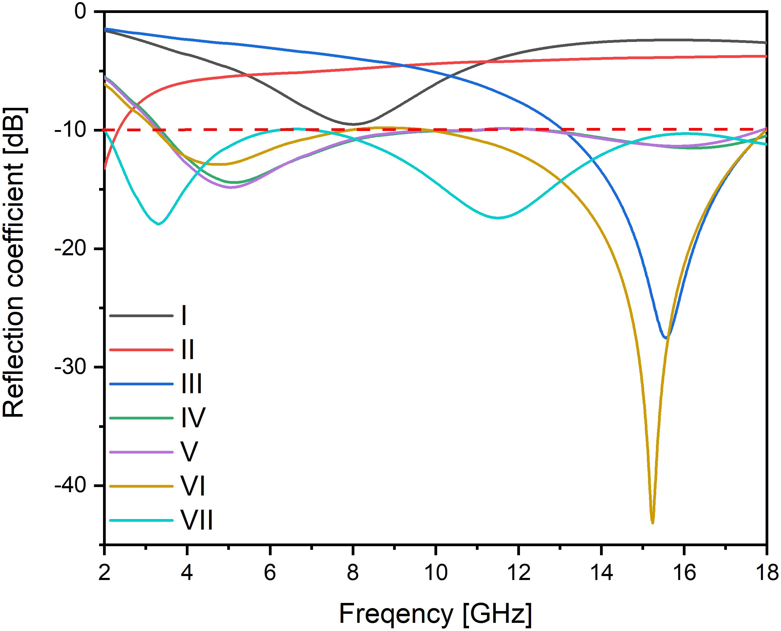
Figure 10: Comparison of monostatic RCS solutions for the PEC cylinder without and with the coating at the incident angle of to the upper circular surface of the cylinder.
By further using the incident wave which is horizontally polarized incidents with an angle of to the upper circular surface of the cylinder, the Poynting vector of the incident wave is parallel to the upper circular surface, and the new different consequences are obtained as shown in Figure10. From the figure, it can be seen that the coating on the cylinder generates a similar RCS reduction to that of the coating on an infinitely large plate. The performance of Type-IV coating is good at a huge part of the frequency band but cannot give a good RCS reduction at nearly GHz. However, the Type-VII coating can reach a low RCS from to GHz and can help RCS to reduce dB in most of the targeted frequency band. The Type-VII coating also has two absorption peaks at and GHz.
V. CONCLUSION
We develop a novel approach to reduce the RCS of targets by using multilayered composite absorbing materials. The first-layer material has a superb impedance matching capability and the second-layer has a good absorption characteristic, and their overlay constitutes the design of multilayered absorbers. In order to design more efficiently, we apply the TLT to analyze the performance of absorbers and employ the PSO to seek the optimal thicknesses of each layer, number of layers, and type of material of each layer. Seven designs with different thicknesses, materials, and numbers of layers are finally figured out and they have shown good performances. Particularly, when we change the incident angle of incident wave from to , it is found that both Type-IV and Type-VII designs among the seven designs are insensitive to the incident angles. Also, they have a small thickness and a broad frequency band. We then coat the designed absorbers on the surface of a PEC cylinder and compare the reductions of RCS between without and with the coating. It is found that the Type-VII coating can provide much more reduction of RCS than the Type-IV coating, especially at low frequencies. In addition, both designs have at least dB reduction of RCS in the most part of the frequency band from to GHz. To sum up, these two material coatings have wide working bandwidths and have high relative bandwidths. They have a high absorptivity when the EM waves are incident vertically. In addition, it can be seen that these materials are angle insensitive relatively in the simulation process of the cylinder. The excellent dielectric constants also make these materials have a certain industrial application ability. The simulation results demonstrate that the designed absorbers can effectively reduce the RCS of real objects and could be good candidates for the stealth designs of targets. More importantly, this method using TLT and PSO algorithms can greatly simplify the original complex design process, save a lot of simulation time, and can be widely used in the design of many kinds ofmaterials.
ACKNOWLEDGMENT
This work was supported by the National Natural Science Foundation of China under the Project No. 62071331 and by the International Science and Technology Collaboration Project of Shanghai Committee of Science and Technology, Shanghai, China, under the project No. 21500714400.
REFERENCES
[1] G. Ruck, Radar Cross Section Handbook: Volume 1, Springer, 1970.
[2] R. Grant, The Radar Game, Mitchell Institute Press, 2010.
[3] F. Wang, Y. Ren, and K. Li, “Broadband RCS reduction of antenna with AMC using gradually concentric ring arrangement,” International Journal of Antennas and Propagation, 2007.
[4] H. Ucar, “Radar cross section reduction,” Journal of Naval Science and Engineering, vol. 9, pp. 72-87, 2013.
[5] W. H. Emerson, “Electromagnetic wave absorbers and anechoic chambers through the years,” IEEE Trans. Antennas Propagat., vol. 21, no. 4, pp. 484-490, Apr. 1973.
[6] E. F. Knott, J. F. SChaeffer, and M. T. Tuly, Radar Cross Section, its Prediction, Measurement and Reduction, Artech House, Norwood, 1985.
[7] M. H. Shams, S. M. A. Salehi, and A. Ghasemi, “Electromagnetic wave absorption characteristic of Mg-Ti substituted Ba-hexaferrite,” Mater. Lett., vol. 62, pp. 1731-1733, 2008.
[8] B. A. Munk, Frequency Selective Surface: Theory and Design, John Wiley & Sons, New York, 2005.
[9] G. T. Ruck, D. E. Barrick, and W. D. Stuart, Radar Cross Section Handbook, Plenum press, New York, 1970.
[10] L. J. Toit, “The design of Jaumann absorbers,” IEEE Trans. Antennas Propagat., vol. 36, no. 6, pp. 17-25, 1994.
[11] K. Sarabandi and N. Behdad, “A frequency selective surface with miniaturized elements,” IEEE Trans. Antennas Propagat., vol. 55, no. 5, pp. 1239-1245, 2007.
[12] N. Landy, S. Sajuyigbe, J. J. Mock, D. R. Smith, and W. J. Padilla, “Perfect metamaterial absorber,” Physical Review Letters, vol. 100, no. 20, pp. 207-402, 2008.
[13] F. Costa, A. Monorchio, and G. Manara, “Theory, Design and Perspectives of Electromagnetic Wave Absorbers,” IEEE Electromagnetic Compatibility Magazine, vol. 5, no. 2, pp. 67-74, 2016.
[14] S. Kasap and P. Capper, Springer Handbook of Electronic and Photonic Materials, Springer,2017.
[15] S. Chejarla, S. R. Thummaluru, S. Kalraiya, and R. K. Chaudhary, “Polarization-angle insensitive metamaterial absorber for wide incident angles,” 2018 3rd International Conference on Microwave and Photonics, pp. 1-2, 2018.
[16] Y. He and J. Jiang, “An ultra-wideband metamaterial absorber with active frequency selective surface,” 2015 9th International Congress on Advanced Electromagnetic Materials in Microwaves and Optics, pp. 100-102, 2015.
[17] R. S. Kshetrimayum, “A brief intro to metamaterials,” IEEE Potentials, vol. 23, no. 5, pp. 44-46, Jan. 2005.
[18] N. Gill, J. Singh, S. Puthucheri, and D. Singh, “Thin and broadband two-layer microwave absorber in 4–12 GHz with developed flaky cobalt material,” Electronic Materials Letters, vol. 14, no. 3, pp. 288-297, 2018.
[19] W. Yuan, Q. Chen, Y. Xu, H. X, S. Bie, and J. Jiang, “Broadband microwave absorption properties of ultrathin composites containing edge-split square-loop FSS embedded in magnetic sheets,” IEEE Antennas and Wireless Propagation Letters, vol. 16, pp. 278-281, 2016.
[20] N. N. Ali, R. A. B. Al-Marieh, Y. Atassi, A. Salloum, A. Malki, and M. Jafarian, “Design of lightweight broadband microwave absorbers in the X-band based on (polyaniline/MnNiZn ferrite) nanocomposites,” Journal of Magnetism and Magnetic Materials, vol. 453, pp. 56-61,2018.
[21] A. Ling, G. Tan, Q. Man, Y. Lou, S. Chen, X. Gu, R. Li, J. Pan, and X. Liu, “Broadband microwave absorbing materials based on MWCNTs’ electromagnetic wave filtering effect,” Composites Part B: Engineering, vol. 171, pp. 214-221, 2019.
[22] V. A. Zhuravlev, V. Suslyaev, E. Y. Korovin, and K. V. Dorozhkin, “Electromagnetic waves absorbing characteristics of composite material containing carbonyl iron particles,” Materials Sciences and Applications, vol. 5, no. 11, pp. 803-811, 2005.
[23] K. J. Vinoy and R. M. Jha, Radar Absorbing Materials: From Theory to Design and Characterization. Kluwer Academic Publishers, Boston, USA, 1996.
[24] Y. Liu, X. Liu, and X. Wang, “Double-layer microwave absorber based on CoFe2O4 ferrite and carbonyl iron composites,” Journal of Alloys and Compounds, vol. 584, pp. 249-253, 2014.
[25] W. Meng, Y. Deng, and S. Li, “Absorption properties of carbonyl-iron/carbon black double- layer microwave absorbers,” Journal of Magnetism and Magnetic Materials, vol. 321, no. 20, pp. 3442-3446, 2009.
[26] V. M. Petrov, and V. V. Gagulin “Microwave absorbing materials,” Inorganic Materials, vol. 37, no. 2, pp. 93-98, 2001.
[27] M. R. Meshram, Nawal K. Agrawal, Bharoti Sinha, and P. S. Misra, “Characterization of M-type barium hexagonal ferrite-based wide band microwave absorber,” Journal of Magnetism and Magnetic Materials, vol. 271, pp. 207-214, 2004.
[28] S. Cui and D. S. Weile, “Particle swarm optimization,” IEEE International Conference on Neural Networks, vol. 4, pp. 1942-1948, 1995.
[29] S. Cui and D. S. Weile, “Application of a parallel particle swarm optimization scheme to the design of electromagnetic absorbers,” IEEE Trans. Antennas Propagat., vol. 53, no. 11, pp. 3616-3624, Nov. 2014.
[30] C. Wei, X. Shen, and F. Song, “Double-layer microwave absorber based on nanocrystalline microfibers,” Materials and Design, vol. 35, pp. 363-368, 2012.
[31] J. Robinson and Y. Rahmat-Samii, “Particle swarm optimization in electromagnetics,” IEEE Trans. Antennas Propagat., vol. 52, no. 2, pp. 397-407, Feb. 2004.
[32] J. Kennedy, “Particle swarm optimization,” Encyclopedia of Machine Learning, pp. 760-766, 2001.
BIOGRAPHIES

Hong Qin Zheng received the B.S. degree in Electrical Engineering from Fuzhou University, Fuzhou, China, in July 2017, and the M.S. degree in Electronic Science and Technology from Tongji University, Shanghai, China, in July 2020. She is currently working in Shanghai Kunqin Information Technology Co., Ltd. as an electronic engineer. She won the third place of the 15th “HUAWEI CUP” National Postgraduate Mathematical Contest in Modeling in 2018. Her research interest is mainly in Applied Computational Electromagnetics.

Yi Tao Huang is an undergraduate student majoring in Microelectronics Science and Engineering in Tongji University, Shanghai, China, and is expected to receive the B.S. degree in July 2023. He has won the first prize of College Students Innovation Experience Competition and the third prize of Tongji University Physics Competition and written two conference papers as the first author. His research interests include antenna design, reduction technique for radar cross section and integrated circuit design.

Mei Song Tong received the B.S. and M.S. Degrees from Huazhong University of Science and Technology, Wuhan, China, respectively, and Ph.D. degree from Arizona State University, Tempe, Arizona, USA, all in electrical engineering. He is currently the Distinguished Professor and Head of Department of Electronic Science and Technology, and Vice Dean of College of Microelectronics, Tongji University, Shanghai, China. He has also held an adjunct professorship at the University of Illinois at Urbana-Champaign, Urbana, Illinois, USA, and an honorary professorship at the University of Hong Kong, China. He has published more than 500 papers in refereed journals and conference proceedings and co-authored 6 books or book chapters. His research interests include electromagnetic field theory, antenna theory and design, simulation and design of RF/microwave circuits and devices, interconnect and packaging analysis, inverse electromagnetic scattering for imaging, and computational electromagnetics.
Prof. Tong is a Fellow of the Electromagnetics Academy, Fellow of the Japan Society for the Promotion of Science (JSPS), and Full Member (Commission B) of the USNC/URSI. He has been the chair of Shanghai Chapter since 2014 and the chair of SIGHT committee in 2018, respectively, in IEEE Antennas and Propagation Society. He has served as an associate editor or guest editor for several well-known international journals, including IEEE Antennas and Propagation Magazine, IEEE Transactions on Antennas and Propagation, IEEE Transactions on Components, Packaging and Manufacturing Technology, International Journal of Numerical Modeling: Electronic Networks, Devices and Fields, Progress in Electromagnetics Research, and Journal of Electromagnetic Waves and Applications, etc. He also frequently served as a session organizer/chair, technical program committee member/chair, and general chair for some prestigious international conferences. He was the recipient of a Visiting Professorship Award from Kyoto University, Japan, in 2012, and from University of Hong Kong, China, in 2013. He advised and coauthored 12 papers that received the Best Student Paper Award from different international conferences. He was the recipient of the Travel Fellowship Award of USNC/URSI for the 31th General Assembly and Scientific Symposium (GASS) in 2014, Advance Award of Science and Technology of Shanghai Municipal Government in 2015, Fellowship Award of JSPS in 2016, Innovation Award of Universities’ Achievements of Ministry of Education of China in 2017, Innovation Achievement Award of Industry-Academia-Research Collaboration of China in 2019, “Jinqiao” Award of Technology Market Association of China in 2020, and Baosteel Education Award of Baosteel Education Foundation of China in 2021. In 2018, he was selected as the Distinguished Lecturer (DL) of IEEE Antennas and Propagation Society for 2019–2021.
ACES JOURNAL, Vol. 37, No. 3, 326–334.
doi: 10.13052/2022.ACES.J.370310
© 2021 River Publishers