Pattern Reconstruction for Antennas with Characteristic Mode Analysis and Surrogate Model
Adem Yilmaz, Hulusi Acikgoz, and Alaa E. El-Rouby
1Department of Electrical and Electronics Engineering, KTO Karatay University, Konya, Turkey
adem.yilmaz@karatay.edu.tr, hulusi.acikgoz@karatay.edu.tr
2Department of Electrical and Electronics Engineering, Ankara Yildirim Beyazit University, Ankara, Turkey
alaa.elrouby@ybu.edu.tr
Submitted On: September 20, 2021; Accepted On: March 17, 2022
Abstract
A novel approach is applied to obtain a desired pattern for a perfect electric plate with two ports. The location of ports is decided with the help of characteristic mode analysis. Two capacitive coupling elements are chosen to be used as excitation. The magnitude and phase of each excitation are obtained by the Bayesian inference method. In order to avoid complexity of computational design, a surrogate model, which is based on polynomial chaos expansion, is built. The surrogate model is ensured to mimic the computational model over 90%. Then, the desired pattern is compared with the synthesized one, and it is seen that the two patterns fit very well to each other and the correlation between the two patterns is above 0.9.
Keywords: Bayesian inference, characteristic mode analysis, pattern synthesis, polynomial chaos expansion.
I. INTRODUCTION
Pattern synthesis has been applied extensively in antenna designs lately since it enhances the performance of the overall antenna system. Traditionally, phased array antennas have been used for this purpose by varying the phase and magnitude of each antenna element [1–3]. However, if one wants to obtain a pattern synthesis within a single antenna, it is challenging since there is only one radiator. However, some literature succeeded to obtain pattern synthesis with an electrically large single antenna, such as reflector antennas [4], leaky wave antennas [5], and horn antennas [6]. On the other hand, there are few studies that synthesize a pattern within a single antenna, namely a conducting plate.
Characteristic mode analysis (CMA) is one of the useful methods to synthesize a desired pattern for a single antenna. In CMA, unique features of scattering and radiation properties can be revealed for any conductive body of arbitrary shape without any excitation [7–10]. Characteristic modes (CMs) are the real current modes that can be numerically computed. Since CMs form a set of orthogonal functions, the total current on the surface of the body is a linear superposition of the CMs. In CMA, the far-field of each mode is also orthogonal to each other. Hence, the desired pattern is the selective excitation of each CM [12]. In order to properly excite the desired CM, capacitive coupling elements (CCEs) and inductive coupling elements (ICEs) can take place in antenna design without any alteration of CMs [13, 14]. Moreover, the desired pattern construction does not only depend on the selection of the coupling element’s type and location, but it also depends on the excitation scheme, i.e., magnitude and phase of each coupling element. Thus, there are some literature papers that investigate to obtain the proper excitation scheme to excite the desired modes and, hence, to obtain the desired pattern. In [15], a multiobjective optimization method is applied to electrically small unmanned aerial vehicle (UAV) and high frequency band antennas for shipboard structures to obtain the desired pattern. In [16], a desired up-tilted beam is achieved by using random search optimization of phases. In [17], the asymmetric CM excitation is observed to obtain a null of an antenna pattern for two ports, and in [18], a linear equation solution is given considering the phase and magnitude of excitation. In [19], a compress sensing algorithm is provided for the desired pattern.
This paper proposes a novel approach to obtain the proper excitation scheme for a desired pattern within a single antenna. The approach is based on the Bayesian inversion that provides the statistical inference of unknown input parameters. The Bayesian inference has already been applied to linear antenna array [20, 21]. However, this paper considers a single antenna, where the main aim is to prove the applicability of the proposed method. The Bayesian framework offers an input parameter quantification based on the measured/computed data in the manner of an inverse problem solving [22]. Indeed, the Bayesian inference method gives a posterior probability distribution over the input with repeated solutions of the forward model. For this purpose, the sampling approach, such as Markov chain Monte Carlo (MCMC) [23], of the input parameters have to be applied at every repeated step during the inverse solution. However, this cannot be affordable when the forward model is computationally expensive. In order to apply Bayesian inference to such a computational design, a surrogate model can be built as a forward model. A surrogate model [24], which is also called metamodel, is a replacement of the high-fidelity computational model with a more efficient surrogate one to avoid the computational burden while studying prediction, optimization, sensitivity analysis, and uncertainty analysis. There are different types of technique that builds surrogate model, such as polynomial chaos expansion (PCE) [25–28], artificial neural networks [29], Gaussian process (Kriging modeling) [30], support vector machines [31], etc. Among them, PCE is chosen in this work due to its advantages such as interpretation and versatility [32]. It has been applied in computational electromagnetic in various areas [33–37]. The PCE depends on three main processes: a random sampling of each input parameter, propagation of such random inputs through the computational model, and then obtention of the random outputs. With input and output data at hand, a model based on the polynomial series can be built. Within a surrogate model, the Bayesian inference can be applicable to complex computational models; hence, one can obtain the values of the excitation scheme for the desired pattern in a single antenna. The organization of this paper is as follows: a brief overview of CMA is given in Section II, and Bayesian inference and PCE are introduced in Section III. The application of the proposed method and the results are given in Section IV. Final conclusions are given in Section V.
II. CHARACTERISTIC MODE ANALYSIS
CMA provides the inherent current modes without any excitation and the total current distribution () is calculated by the sum of orthogonal current modes ()
| (1) |
where are called modal weighting coefficients (MWC), and they are related to the current modes . are natural current distributions that do not depend on the excitation. On the contrary, MWCs are strongly dependent on the excitation; thus, the desired current distribution on the structure under consideration is dependent on the selective excitation of the modes. In order to excite the desired modes properly, the locations of the external excitation source (port) should be carefullyinvestigated.
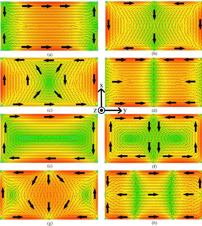
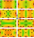
Figure 1: Current distribution on the conducting plate related to the number of modes (a) 1, (b) 2, (c) 3, (d) 4, (e) 5, (f) 6, (g) 7, and (h) 8 (arrows indicate the direction of current).
In this paper, a conducting plate with dimensions of 150 75 mm is considered to obtain a desired pattern. One of the possible patterns that can be obtained by a PEC plate is a null pattern on the upper half of the plate, which has been successfully achieved in [17], where asymmetric excitation of the phase of the ports are considered and null patterns are obtained between and . In order to determine the location of the ports for a desired null pattern, the current distribution of the first eight modes is investigated with CMA and the results are illustrated in Figure 1. The location of ports can be determined with the current or electric field maxima of each mode. A desired mode can be excited by placing a CCE at a current minimum or placing an ICE at a current maximum [14]. One can see from Figure 1 that mode 1, mode 4, and mode 8 can be properly excited by locating the CCE in the middle of the short edges, where the current is minimum, i.e., the maximum of E-field. Similarly, CCE can be placed in the middle of the long edges to excite mode 2, mode 4, and mode 7. Since the current distributions of mode 4 and mode 8 are mostly along the y-direction, it is possible to obtain a null pattern on the upper half of plate. For that reason, these two modes are desired to be excited by placing CCE at the minimum current distribution, i.e., at the middle of the short edges. The overall structure with two CCE ports is illustrated in Figure 2. Once the locations of the excitation (two CCE ports) are determined with the help of CMA, the phase and magnitude of ports should be specified for a desired pattern. In this work, this is achieved with a surrogate model and Bayesianinversion.
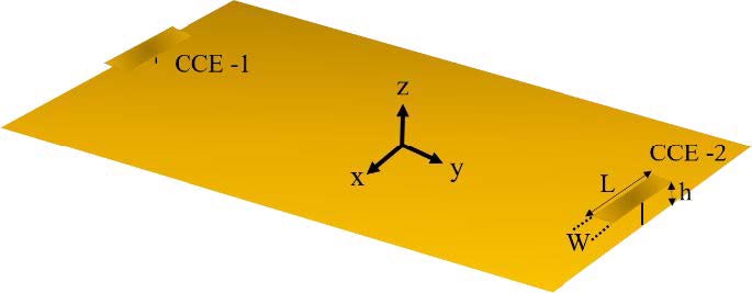
Figure 2: Overall structure with two CCE ports (L = 25.5 mm, W = 9.5 mm, and h = 4 mm).
III. POLYNOMIAL CHAOS EXPANSION AND BAYESIAN INFERENCE
A. Polynomial chaos expansion
PCE can be used to build a surrogate model which substitutes the computationally expensive models with an easy to work surrogate model. In PCE, the response of the system (Y) is computed by the independent input parameters of (X) and the polynomial expansion for building the surrogate model is given by
| (2) |
where the are the multivariate polynomials, are the multi-indices that identify the components of , and are the expansion coefficients to be determined. There are two main approaches to compute the expansion coefficients: intrusive and non-intrusive methods. The former indicates the modification of the underlying code of the computational model, while the latter one considers the computational model as a black box; thus, one does not need to modify the code to build the model. The least-squares minimization is one of the strategies that compute the expansion coefficients non-intrusively. In practice, the infinite sum in eqn (2) needs to be truncated to a finite sum for the computational purpose. In PCE, the number of polynomial basis is calculated as
| (3) |
where is the number of input variables and is the degree of the polynomial. One can understand from eqn (3) that if the input parameters are high and/or the degree of the polynomial are set to a high degree to ensure the accuracy of the surrogate model, then a large number of polynomials have to be taken into account. To avoid working with the high-dimensional polynomial basis, the least angle regression selection (LARS) algorithm can be applied to reduce the number of polynomial bases. There are two main ways to estimate the error between the computational model and the surrogate model. The normalized empirical error is a generalization error based on the accuracy with which the surrogate model reproduces the computational model evaluations. However, it is also well-known that if the polynomial model is too complex, an overfitting problem may occur. In order to overcome this problem, the leave-one-out cross-validation (error) technique is usually performed as an alternative way.
B. Bayesian inference
Bayesian inference is one of the statistical inference methods that are based on the Bayes’ rule. In this method, the unknown parameters of the prior probability density function (PDF) are inferenced by integrating prior information and the observations through the inference of the posterior as
| (4) |
where
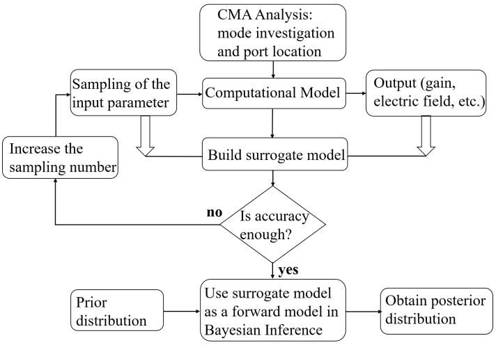
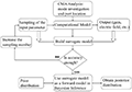
Figure 3: Proposed procedure for obtaining desired pattern.
IV. APPLICATION AND RESULTS
A. Pattern synthesis with two CCE ports
In order to obtain a proper excitation scheme for the desired pattern, a general framework in this study is given in Figure 3 and summarized as following steps:
1) CMA is applied to the structure under consideration. The current distribution of each mode is investigated. The locations of ports are identified. Then, the computational model, including ports, is constructed.
2) Random sampling of input parameters (phase and magnitude of each port) is performed. Then, the random samples are propagated through the computational model. The output values of the overall structure, such as gain, total electric field, etc., are obtained for each random input.
3) The inputs/outputs set given by the computational model is presented to the PCE to build a surrogate model. The accuracy of the surrogate model is investigated to ensure that the surrogate model mimics the computational model successfully.
4) The surrogate model is given to the Bayesian scheme a forward model. Prior distribution is chosen to be consistent with the random sampling range. Posterior distribution is obtained for the desired pattern.
5) Post-processing on the results of Bayesian inference is performed. The MAP is applied to choose the best candidate for input parameters.
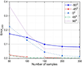
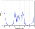
As discussed in Section II, the main aim in this work is to obtain a null pattern at the upper hemisphere of the plate, and to achieve that purpose, the first step stated in Figure 3 is accomplished in Section II. In the next step, the phase and magnitude of each CCE ports are randomly and independently sampled between allowable regions, i.e., [] and [0, 1 V], respectively, to build a surrogate model. The sampled input is given to the computational model and the output, namely total normalized electric field, of each sample is obtained by method of moments. The number of samples is increased step by step to ensure that the sample number is adequate for an accurate model. As mentioned in Section III, the error is the quantification of how well the surrogate model mimics the computational model. So, at each increased step, a surrogate model is built and the error is examined. In Figure 4, five elevation angles are chosen to explore the effect of increased sample number on error. One can say that the 150 samples are sufficient to build relatively accurate model since the error does not decrease further. This finding is also observed for all elevation angles. Moreover, the total error for all elevation angles is illustrated in Figure 5 for chosen 150 sample numbers. One can keep in mind that increasing the number of samples will bring a computational burden; hence, the number of samples is kept as 150 in this work.
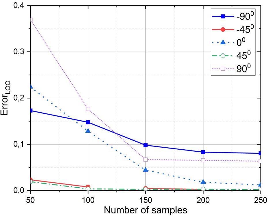
Figure 4: Error variation while increasing sample number.
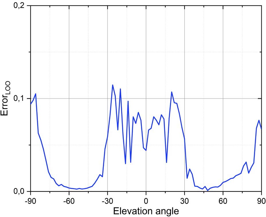
Figure 5: Error for all elevation angles with 150 sample numbers.
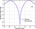
Once the surrogate model is built and the accuracy of the model is ensured, it is conveyed to the Bayesian framework as a forward model. Since the input parameters do not follow any specific distribution, the prior distributions in Bayesian inference are given as a uniform distribution between the [] for phases and [0, 1 V] for magnitudes. The posterior distribution in Bayesian inference is obtained for the desired pattern. In this work, the null patterns at various elevation angles between [] are considered as the desired pattern. For illustration purpose, two cases are taken into consideration: case 1 is a desired pattern with a null at and case 2 is a desired pattern with two nulls at around . Then, the Bayesian framework is conducted, and the results are examined. The mode of each output distribution is chosen as the best candidate for phases and magnitudes. As a final step, the results obtained from Bayesian inference are given to the computational model to compare the desired pattern with the synthesized one given by the forward computational model. The excitation scheme of ports for two cases is given in Table 1. One can keep in mind that the structure under consideration exhibits repetitive pattern that depends on the phase differences between two ports. For that reason, the desired phase difference is achieved with different phase values in case 1. In Figure 6, one can say that the Bayesian framework works well to identify the magnitude and phase of ports in a single antenna for obtaining a desired pattern. Moreover, the correlations between desired and synthesized patterns are 0.9389 for case 1 and 0.9717 case 2, which indicates that the two patterns fit very well [12, 14].
Table 1: The excitation scheme for two cases
| 45 | 90 | 0.5 | 0.75 | ||
| 45 | 90 | 0.5 | 0.75 | ||
| 93 | 98 | 0.51 | 0.69 | ||
| 78 | 93 | 0.53 | 0.69 |
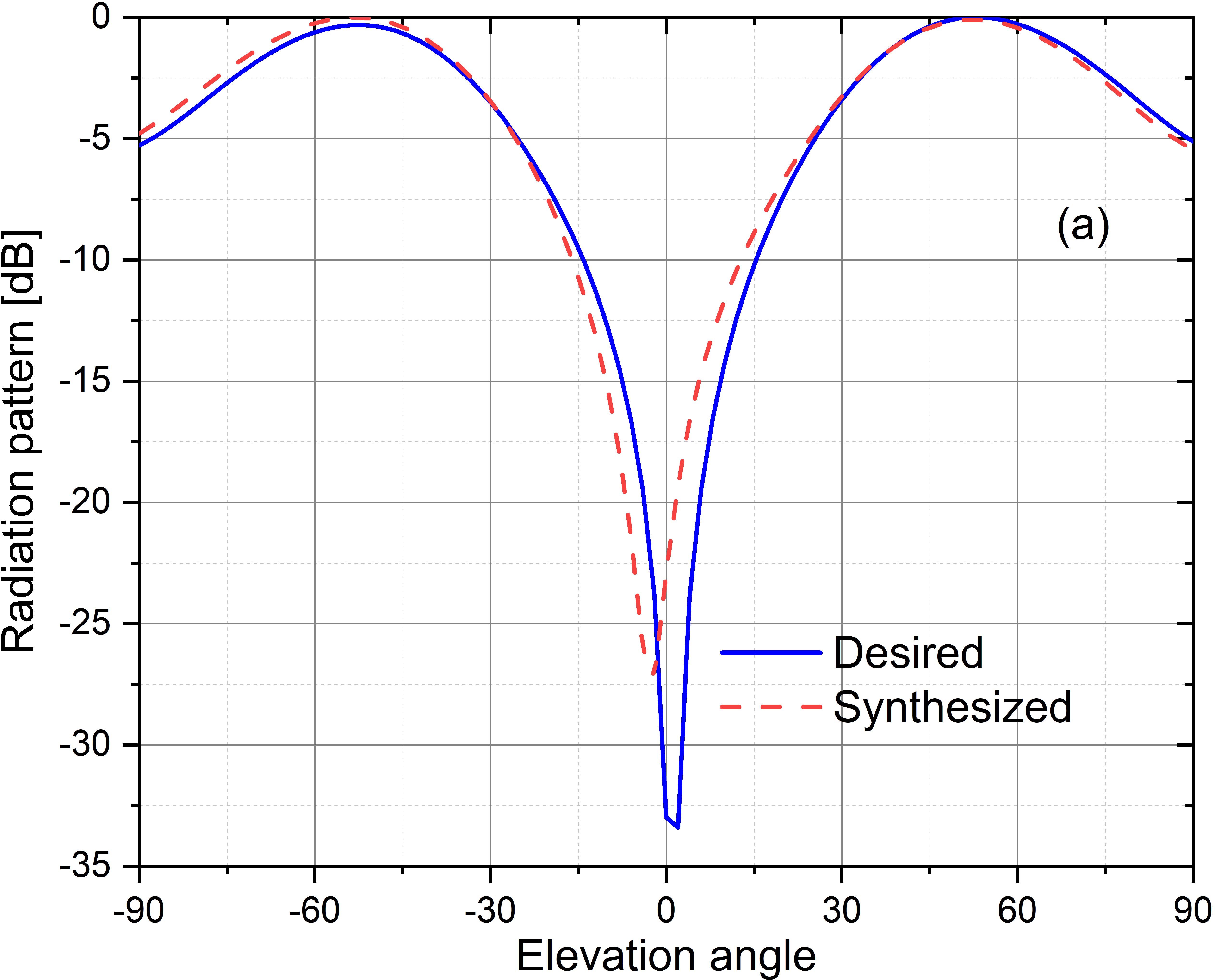
Figure 6: Desired and synthesized patterns. (a) Case 1. (b) Case 2.
B. CCE port design
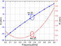
The dimensions of CCE ports are selected to have an input impedance to have only real part of impedance at the operating frequency. For this purpose, the procedure for obtaining a desired pattern given in Figure 3 is also applied to choose the dimension of the CCE ports. In this case, the input parameters for Bayesian framework are the dimensions of the CCE ports. The varied dimensions of CCE ports are length, width, and the height of the CCE from the PEC plate (see Figure 2).
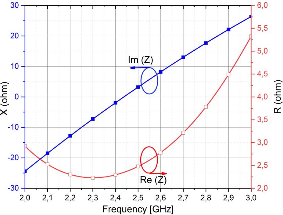
Figure 7: Real and imaginary impedances.
Each input parameter is randomly sampled between the ranges given in Table 2. The limits of ranges are deliberately chosen to be comparable with practical application purposes. A surrogate model is built with 100 random samples of each input parameter, and it is conveyed to Bayesian framework as a forward model. A desired distribution, which mimics a real input impedance value, is given in Bayesian inference. The MAP is applied on the results of the Bayesian inference, and it is obtained that the length L = 25.5 mm, the width W = 9.5 mm, and the height h = 4 mm are the best candidates for a nearly zero imaginary part of the impedance. The CCE ports are designed with obtained values, and both real and imaginary parts of port impedances are illustrated in Figure 7. One can say that the imaginary part of the impedance is nearly zero at operating frequency while real part is at around 2.5 . For practical application purposes, this real impedance can be easily matched to 50 by an impedance matching circuit.
Table 2: CCE port dimensions (in mm)
| [5–65] | [2–15] | [4–10] |
|---|
V. CONCLUSION
A procedure for pattern synthesis for an antenna is proposed. The procedure is based on two main theories: CMA and Bayesian inference. The CMA has been applied to identify the locations of ports. Two CCE ports are properly placed on conducting plate. To avoid the computational complexity, a surrogate model is built with PCE. The surrogate model is used as a forward model in Bayesian inference to efficiently obtain the unknown input parameters for a desired pattern. Two desired patterns that exhibit nulls at upper hemisphere of the plate are achieved by the proposed procedure with good agreement. The proposed procedure can be applied to more complex computational models, which remain as future works.
REFERENCES
[1] D. W. Boeringer and D. H. Werner, “Particle swarm optimization versus genetic algorithms for phased array synthesis,” IEEE Trans. Antennas Propag., vol. 52, no. 3, 2004.
[2] K. K. Yan and Y. Lu, “Sidelobe reduction in array-pattern synthesis using genetic algorithm,” IEEE IEEE Trans. Antennas Propag., vol. 45, no. 7, 1997.
[3] H. Lebret and S. Boyd, “Antenna array pattern synthesis via convex optimization,” IEEE Trans. Signal Process., vol. 45, no. 3, 1997.
[4] A. Foudazi and A. R. Mallahzadeh, “Pattern synthesis for multi-feed reflector antennas using invasive weed optimisation,” IET Microw. Antennas Propag., vol. 6, no. 14, 2012.
[5] J. L. Gomez-Tornero, A. J. Martinez-Ros, and R. Verdu-Monedero, “FFT synthesis of radiation patterns with wide nulls using tapered leaky-wave antennas,” IEEE Antennas Wirel. Propag. Lett., vol. 9, 2010.
[6] M. A. Moharram and A. A. Kishk, “Optimum feeds for reflectarray antenna: synthesis and design,” IEEE Trans. Antennas Propag., vol. 64, no. 2, 2016.
[7] R. Garbacz and R. Turpin, “A generalized expansion for radiated and scattered fields,” IEEE Trans. Antennas Propag., vol. 19, no. 3, pp. 348-358, 1971.
[8] R. F. Harrington and J. R. Mautz, “Theory of characteristic modes for conducting bodies,” IEEE Trans. Antennas Propag., vol. 19, no. 5, pp. 622-628, 1971.
[9] R. Harrington and J. Mautz, “Computation of characteristic modes for conducting bodies,” IEEE Trans. Antennas Propag., vol. 19, no. 5, pp. 629-639, 1971.
[10] A. Araghi and G. Dadashzadeh, “Detail-oriented design of a dual-mode antenna with orthogonal radiation patterns utilizing theory of characteristic modes,” Applied Computational Electromagnetics Society (ACES) Journal, vol. 28, no. 10, pp. 952-959, 2013.
[11] N. Michishita and H. Morishita, “Helmet antenna design using characteristic mode analysis,” Applied Computational Electromagnetics Society (ACES) Journal, vol. 35, no. 2, pp. 161-166, 2020.
[12] E. Safin and D. Manteuffel, “Reconstruction of the characteristic modes on an antenna based on the radiated far field,” IEEE Trans. Antennas Propag., vol. 61, no. 6, pp. 2964-2971, 2013.
[13] R. Valkonen, A. Lehtovuori, and D. Manteuffel, “Capacitive coupling elements - Changing the way of designing antennas,” in The 8th European Conference on Antennas and Propagation (EuCAP 2014), no. EuCAP, pp. 229-233, Apr. 2014.
[14] D. Manteuffel and R. Martens, “Systematic design method of a mobile multiple antenna system using the theory of characteristic modes,” IET Microw., Antennas Propag., vol. 8, no. 12, pp. 887-893, 2014.
[15] Y. Chen and C.-F. Wang, “HF band shipboard antenna design using characteristic modes,” IEEE Trans. Antennas Propag., vol. 63, no. 3, pp. 1004-1013, 2015.
[16] Z. Liang, J. Ouyang, F. Yang, and L. Zhou, “Design of license plate rfid tag antenna using characteristic mode pattern synthesis,” IEEE Trans. Antennas Propag., vol. 65, no. 10, pp. 4964-4970, 2017.
[17] F. A. Dicandia, S. Genovesi, and A. Monorchio, “Null-steering antenna design using phase-shifted characteristic modes,” IEEE Trans. Antennas Propag., vol. 64, no. 7, pp. 2698-2706, 2016.
[18] F. A. Dicandia, S. Genovesi, and A. Monorchio, “Advantageous exploitation of characteristic modes analysis for the design of 3-D null-scanning antennas,” IEEE Trans. Antennas Propag., vol. 65, no. 8, pp. 3924-3934, 2017.
[19] H. Li, S. Sun, W. Li, M. Wu, and C. Zhou, “Systematic pattern synthesis for single antennas using characteristic mode analysis,” IEEE Trans. Antennas Propag., vol. 68, no. 7, pp. 5199-5208, 2020.
[20] C. Y. Chan and P. M. Goggans, “Using Bayesian inference for linear antenna array design,” IEEE Trans. Antennas Propag., vol. 59, no. 9, 2011.
[21] C. Y. Chan and P. M. Goggans, “Multiobjective design of linear antenna arrays using bayesian inference framework,” IEEE Trans. Antennas Propag., vol. 62, no. 11, 2014.
[22] A. Gelman, J. B. Carlin, H. S. Stern, D. B. Dunson, A. Vehtari, and D. B. Rubin, Bayesian Data Analysis, Third Edition, 2013.
[23] G. C. Christian P. Robert, Monte Carlo Statistical Methods - 2nd Edition, vol. 109, no. 1, 2004.
[24] R. W. Blanning, “The construction and implementation of metamodels,” SIMULATION, vol. 24, no. 6, pp. 177-184, 1975.
[25] B. Sudret, “Uncertainty propagation and sensitivity analysis in mechanical models – Contributions to structural reliability and stochastic spectral methods,” Habilitation à diriger des recherches, Université Blaise Pascal, Clermont-Ferrand, France , 2007.
[26] B. Sudret, “Global sensitivity analysis using polynomial chaos expansions,” Reliab. Eng. Sys. Safety, vol. 93, no. 7, pp. 946-979, 2008.
[27] K. Sepahvand, S. Marburg, and H. J. Hardtke, “Uncertainty quantification in stochastic systems using polynomial chaos expansion,” Int. J. Appl. Mech., vol. 2, no. 2, 2010.
[28] P. Kersaudy, S. Mostarshedi, B. Sudret, O. Picon, and J. Wiart, “Stochastic analysis of scattered field by building facades using polynomial chaos,” IEEE Trans. Antennas Propag., vol. 62, no. 12, 2014.
[29] D. J. C. MacKay, “Bayesian methods for adaptive models,” Computation and Neural Systems, California Institute of Technology, Pasadena, CA, 1991.
[30] J. P. C. Kleijnen, “Kriging metamodeling in simulation: A review,” Eur. J. Oper. Res., vol. 192, no. 3. 2009.
[31] X. Zhang, R. Srinivasan, and M. van Liew, “Approximating SWAT model using artificial neural network and support vector machine,” J. Am. Water Resour. Assoc., vol. 45, no. 2, 2009.
[32] Z. Liu, D. Lesselier, B. Sudret, and J. Wiart, “Surrogate modeling based on resampled polynomial chaos expansions,” Reliab. Eng. Sys. Safety, vol. 202, p. 107008, Oct. 2020.
[33] F. Boeykens, H. Rogier, and L. Vallozzi, “An efficient technique based on polynomial chaos to model the uncertainty in the resonance frequency of textile antennas due to bending,” IEEE Trans. Antennas Propag., vol. 62, no. 3, 2014.
[34] H. Acikgoz and R. Mittra, “Stochastic polynomial chaos expansion analysis of a split-ring resonator at terahertz frequencies,” IEEE Trans. Antennas Propag., vol. 66, no. 4, 2018.
[35] C. Chauvière, J. S. Hesthaven, and L. Lurati, “Computational modeling of uncertainty in time-domain electromagnetics,” SIAM J. Sci. Comput., vol. 28, no. 2, 2006.
[36] H. Acikgoz, R. K. Arya, and R. Mittra, “Statistical analysis of 3D-printed flat GRIN lenses,” in 2016 IEEE International Symposium on Antennas and Propagation (APSURSI), pp. 473-474, Jun. 2016.
[37] H. Acikgoz, R. K. Arya, J. Wiart, and R. Mittra, “Statistical electromagnetics for antennas,” in Developments in Antenna Analysis and Design: Volume 2, Institution of Engineering and Technology, pp. 259-286, 2018.
[38] S. Marelli and B. Sudret, “UQLab user manual – Polynomial chaos expansions,” 2019.
[39] P.-R. Wagner, J. Nagel, S. Marelli, and B. Sudret, “UQLab user manual – Bayesian inversion for model calibration and validation,” ETH Zurich, 2021.
BIOGRAPHIES

Adem Yilmaz received the B.S. and M.S. degrees in electrical and electronics engineering from the University of Gaziantep and Ankara Yildirim Beyazit University, respectively. He is currently working toward the Ph.D. degree with Ankara Yildirim Beyazit University, Turkey.
From 2010 to 2011, he was a Researcher with Goethe Frankfurt University, Germany. Since 2011, he has been a Research Assistant with KTO Karatay University. His research interests include computational electromagnetics, the theory of characteristic modes, and design and characterization of periodic structures.

Hulusi Acikgoz received the B.S. and master’s degrees in applied physics from Marne-La-Vallée University, France, and the Ph.D. degree in electrical engineering from Pierre and Marie Curie University, Paris, France, in 2008.
He has been a Teaching Assistant with UPMC-Paris IV from 2009 to 2010. After a year of post-doctoral research at L2E (Laboratoire d’Electronique et d’Electromagn Supétisme) in computational electromagnetic dosimetry, he joined KTO Karatay University, Konya, Turkey, in 2011, as an Associate Professor. His research interests include microwave characterization of dielectric materials, electromagnetic dosimetry, homogenization, antennas for microwave cancer ablation, high impedance surfaces, graphene applications in EM, and statistical analysis of EM structures.

Alaa E. El-Rouby received the B.Sc. and M.Sc. degrees from Cairo University, Egypt, in 1993 and 1996, respectively, and the Ph.D. degree from the University of Michigan, Ann Arbor, MI, USA, in 2000, all in electrical engineering.
He started his academic career as an Assistant Professor, and he was then an Associate
Professor with Cairo University till 2014. He then moved to Yildirim Beyazit University, where he is currently a Professor. Dr. Elrouby had a strong connection with semiconductor industry through working for Intel Corp. and then for Mentor Graphics for over 14 years. Since 2015, he has been working as a consultant for RF/MW, antenna, GNSS, PCB, and signal and power integrity, which are his current research interestsas well.
ACES JOURNAL, Vol. 37, No. 3, 273–280.
doi: 10.13052/2022.ACES.J.370303
© 2021 River Publishers