Solar Cell Integrated Wearable Patch Antenna on Artificial Magnetic Conductor for On-Body and In-Body Communications
Suresh Babu T. Naganathan and Sivakumar Dhandapani
1Department of Electronics and Communication Engineering
Adhiparasakthi Engineering College, Melmaruvathur 603319, India
sureshbabutns@gmail.com
2Department of Electronics and Communication Engineering
Easwari Engineering College, Chennai 600089, India
dgsivakumar@gmail.com
Submitted On: September 23, 2021; Accepted On: July 9, 2022
Abstract
This paper presents a patch antenna on a jeans textile with an artificial magnetic conductor (AMC) structure stacked on a solar cell for wearable applications in the Industrial, Scientific, and Medical (ISM) band. Meanwhile, the loading of the AMC reflector increases the radiation efficiency and antenna gain and also results in a reduction in specific absorption rate levels. As examination cases, two textile antenna designs loaded on 7 8 patches of AMC plane with the ground plane of both fully copper conductor and partially copper aided with solar cells were fabricated and tested, presenting a strong agreement between simulation and measurement. Its measured impedance bandwidth is 13.79% (2.16 GHz–2.48 GHz) with good return loss and voltage standing wave ratio features in the operating band where it is being used. Besides being a source of electricity, the silicon solar cells are also used as a radio frequency ground plane for the AMC plane. They can produce363.08 mW.
Index Terms: Artificial magnetic conductor (AMC), integrated antennas, patch antennas, solar cells, wearable antennas, wireless body area networks (WBAN).
I. INTRODUCTION
The evolution of technology is important only when it is harmonized with our mother nature. So, while developing any technology, the environment should be the utmost priority. Wireless communication is the most emergent, prolific, and accepted area of the communication field. So far, research efforts focus on spectrum efficiency, transmission reliability, data rate, and services provided to users [1–3]. However, most of the recent research efforts have disregarded the implications of wireless networks’ environmental responsibility, e.g., energy efficiency and environmental impact [4, 5]. Green energy may even require its surroundings to help generate power, making it mostly unpredictable. This is where smart technology and the internet of things (IoT) come into play [6–8].
Green wireless communication will provide energy-efficient communication. It will result in less radiation from devices as well as more economic solutions for service providers, and they will also strive to reduce their carbon footprint [9–11]. The integration of the solar cell with an antenna, called “green antennas,” can be used for advanced wireless technologies for energy-efficient green communication. As for renewable energy, solar cells are becoming an important source by virtue of their cleanliness and safety. Indeed, silicon solar cells can be utilized as both a radiating patch [12–15] and an antenna ground plane [16–21] due to its conducting properties.
The GaAs solar cell patches [12] were utilized to demonstrate the antenna structure, instead of copper patches. The authors demonstrated that the patch antenna is stacked with a solar cell [13–15] for wireless local area network (WLAN), worldwide interoperability for microwave access (Wi-Max) and wireless fidelity (Wi-Fi) applications, where the solar cell performs as an RF patch section notwithstanding its direct current (DC) generation. The variation of the reflection coefficient of the multiband patch antenna loaded in slots with and without solar cell stacking was addressed [13]. The influence of solar cell operation on RF antenna performance was investigated by combining a DC/RF isolation circuit [14]. The investigation into the performance of solar cell ground plane [16] for antenna design on FR4 substrate was discussed. Also presented were silicon solar cells used as microwave ground planes with patch antennas on the FR4 substrate for WLAN applications [17], thin film glass substrate for wireless communications [18], airborne communication nodes [19], Plexiglas substrate for remote area applications [20], and the FR4 substrate for future mobile communications [21]. Changes in solar cell DC power production with and without antennas were also examined [20, 21].
Recently, advancements in technology in solar cell research have allowed their size to be reduced to such an extent that they can be easily sewn onto items of clothing without appearing presently bulky [22, 23]. Solar clothing uses photovoltaic cells in order to harness the sun’s energy and use it to power electronic gadgets. Initially, copper and, after that, fabric-conducting materials are used as the conducting parts of the wearable antennas. For fabricating the wearable antennas, different types of non-conducting fabric dielectric materials are used. For high performance radio LAN (HIPERLAN) applications, the radiation performance of copper-based and Zelt-based conductive fabric-based wearable patch antennas [24] aided by polyester fabric substrate was investigated. Under bending and crumpling conditions, the copper foil koch fractal wearable dipole antenna in the very high frequency (VHF) band (430 MHz–475 MHz) for military applications [25] and the ring resonator wearable patch antenna [27] at 5.8 GHz aided with a common jeans cotton substrate were investigated. A parametric study was demonstrated on the rectangular textile patch antenna [26], which was made from both copper and nickel-plated polyester fabric with a denim substrate for ISM band wireless body-area network applications. Wearable patch antennas with different electro-textile materials were fabricated, and their radiation performance was discussed [28, 30]. The performance of a new embroidered wearable antenna on a Felt substrate [29] was demonstrated and tested. A brief study on wearable antennas for dual-band operation [31–33], dual-mode single band operation [34] and ultra-wideband (UWB) operation [35] was alsoreported.
The electromagnetic band-gap (EBG) structure has captivated researchers due to its desirable unique band-gap features, which have been discovered to be used in suppressing surface waves and improving performance in wearable antenna designs [36, 37], such as bandwidth, gain, compactness, and so on, for wireless body area network applications. Furthermore, metasurfaces have inspired a wide range of applications in wearable antennas, where they are used not only to improve the properties of antennas, such as bandwidth and gain, but also to ensure the antenna will work at an appropriate frequency. Metasurface-based wearable antennas are presented and discussed for their performance in the dual-band [38, 39] operation, the ISM band [40], UWB [41], and also X-band [42] applications. The use of metamaterials for SAR reduction [43] is being investigated in the context of designing communication equipment for safety compliance.
An AMC is a metamaterial that imitates the attributes of a permanent magnetic conductor (PMC). AMC can be useful in wireless body area networks (WBAN) because it allows for better transmission and less backward radiation [44, 45]. Additionally, the operating frequency range of the antenna is closely related to the bandwidth of the AMC. The dual-band wearable antenna loaded with AMC was presented for WLAN applications [46]. The ability of the AMC to reduce SAR for wearable antenna design [47–53] was discussed. The textile patch antenna associated with the solar cell has not been discussed in detail to date.
In this article, an AMC loaded textile patch antenna with and without integrated solar cells is demonstrated and its radiation performance is studied. This paper is organized as follows: Section II describes the proposed antenna design and its fabrication. Section III describes high-frequency structure simulator (HFSS) antenna simulation analysis compared with measurement results and also the solar cell parametric measurement with and without the antenna. Finally, Section IV shows the conclusion.
II. ANTENNA DESIGN AND FABRICATION
The proposed textile antenna layout consists of two modules, and it is shown in Figure 1. One of them is the patch antenna module, and the other is the AMC reflector module.
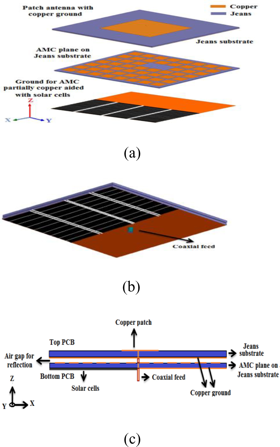
Figure 1: Antenna layout: (a) 3D layout of the proposed patch antenna on the AMC plane with partially aided solar cells; (b) proposed antenna coaxial feed view; (c) proposed antenna side view.
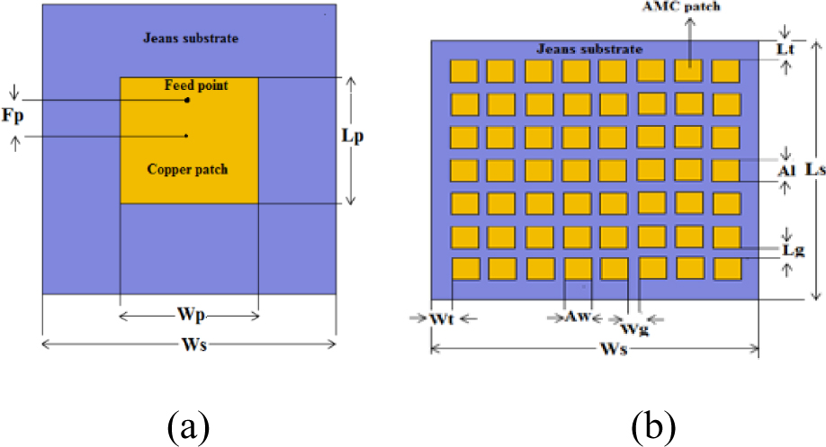
Figure 2: Geometry of the proposed antenna: (a) patch antenna (top module); (b) AMC plane (bottom module).
In the upper module, there are three layers that are of focus: the patch, substrate, and ground plane. Similarly, in the lower module, there are three layers: the AMC reflector plane, substrate, and ground plane. In both modules, the conducting parts (patch, AMC plane, and ground plane) are made of copper foil with a thickness of 0.025 mm, whereas the substrate part is Jeans fabric with a relative permittivity () of 1.67, a loss tangent () of 0.02, and a thickness (h) of 2 mm. The jeans fabric and copper foil have been cut manually. In this study, two designs of antenna models are demonstrated. The first model is an incorporated patch antenna (top module) with a fully copper-grounded AMC module (bottom module), and the second one is the same incorporation with a partially copper-grounded AMC module, aided with solar cells.
The top patch antenna module of the proposed model is designed by using a transmission line model and its geometry is shown in Figure 2(a). The patch antenna consists of a top copper patch with a size of 46 mm 51 mm and a bottom copper ground with a size of 96 mm 101 mm, which is glued using fabric glue onto a Jeans substrate with a size of 96 mm 101 mm. The feed point is carefully chosen through HFSS V.15 of ANSYS for good impedance matching. As shown in Figure 2(b), the bottom AMC module is made up of a 7 8 array of copper foil square unit patches, and each AMC unit cell measures 10 mm 10 mm and is glued on the same size as the top module of the Jeans substrate. Their optimized dimensions are summarized in Table 1.
Table 1: Optimized dimensions of the proposed antenna
| Parameters | Value (mm) | Parameters | Value (mm) |
| Lp | 46 | Lt | 4 |
| Wp | 51 | Wt | 3.5 |
| Ls | 96 | Al | 10 |
| Ws | 101 | Aw | 10 |
| Fp | 16 | Lg | 3 |
| – | – | Wg | 2 |
The AMC unit cells are arranged periodically in equal spaces and cover the entire area of the substrate. The fabricated modules are shown in Figure 3(a) and (b). The ground plane of the AMC module for the two proposed cases: the first one is glued with copper foil, and the second one is partially copper foil soldered with the solar cells under investigation.
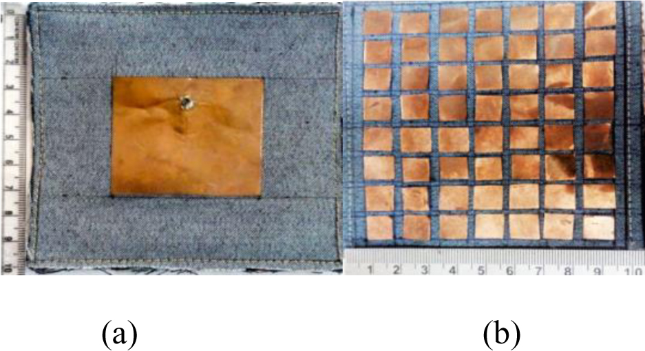
Figure 3: Fabrication of the proposed antenna modules: (a) patch antenna; (b) AMC plane.
In the first case, the fabricated AMC reflector plane with a copper ground plane is situated underneath the patch antenna, keeping an air gap of 1 mm between the assemblies. This is shown in Figure 4. The inner conductor of the coaxial RF connector is associated with the feed point of the upper patch module, which provides a good impedance match [54]. Therefore, the outer conductor is associated with the ground of the patch and the AMC reflector.
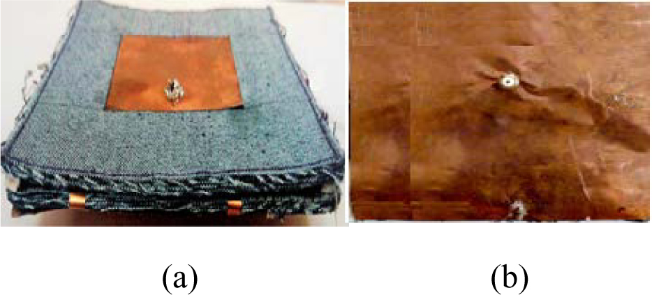
Figure 4: Patch antenna integrated on the AMC plane with copper ground plane: (a) front side view; (b) back side view.
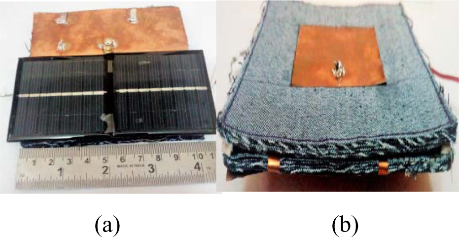
Figure 5: Patch antenna integrated on the AMC plane aided with solar cell ground plane: (a) front side view; (b) back side view.
For the subsequent case, the second module is fabricated as in the first case; except the ground plane is modified by the half-done copper ground plane soldered with the negative terminal of the two series connected 4 V, 100 mA solar cells with dimensions of 60 mm 60 mm 1.5 mm. The front side and back side views of the fabricated subsequent modules are shown in Figure 5.
This section covers a key strategy for determining the dielectric constant of jeans, chosen for antenna fabrication under microwave frequencies. The exploratory arrangement of the microwave test bench and the dielectric constant measurement setup of jeans under test are indicated schematically in Figure 6. A standing wavepattern will be produced by turning on the klystron power supply and the klystron tube. The general procedure for the measurement of guide wave length () and frequency (f) of the signal is reported [55].
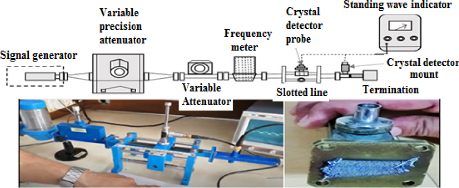
Figure 6: Experimental setup of a microwave bench and dielectric constant measurement.
The probe shall be kept at a minima position, and the reading on the bench shall be taken. The jeans under test will be put in the wave guide in contact with the short circuit plate and the position of the new displaced minima will be recorded. The difference between the two positions of the minima shall be the shift () caused by the inclusion of the jean dielectric. The dielectric constant will be determined utilizing the formulae detailed in [55, 56], and the measured value of the dielectric constant of the jeans under test is 1.67.
III. SIMULATION AND MEASUREMENT RESULTS
The simulation process is carried out step-by-step using HFSS V.15. To compute the electrical behavior of complex components with arbitrary shapes and user-defined material properties, HFSS V.15 employs a 3D full-wave Finite Element Method (FEM) field solver. Initially, the top patch antenna module is simulated, and the result indicates that the return loss (S) of better than -10 dB is attainable over the 2.38 GHz–2.48 GHz band with a center frequency of 2.42 GHz and an impedance bandwidth of 4.13%. The realized peak gain of the proposed patch antenna under simulation is4.51 dBi.
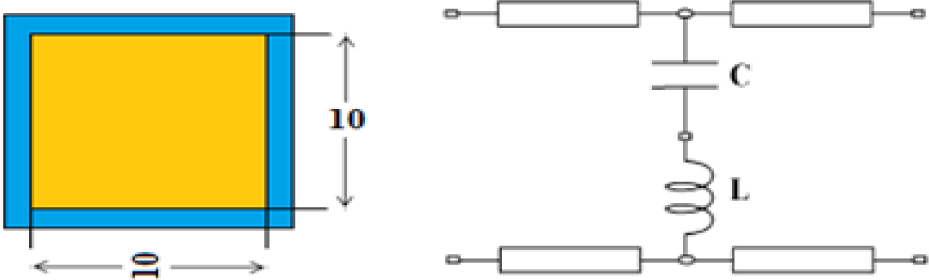
Figure 7: Geometry of an AMC unit cell with its typical equivalent circuit.
Furthermore, a standardized model for a capacitive partially reflective surface screen and its equivalent circuit representation are employed here to facilitate the analysis of AMC. The geometry of the AMC unit cell and its equivalent circuit representation [57] are shown in Figure 7, where the conducting element is represented by the inductor and the inter-element capacitance by the capacitor. Subsequently, the reflection phase characteristic of the AMC unit cell against frequency with suitable boundary conditions [57, 58] was simulated. A single cell of the structure was studied using periodic boundary conditions on its sides to simulate an infinite structure [44]. The simulation setup and the resultant reflection phase characteristic of the AMC unit cell against frequency are shown in Figure 8(a) and (b). Meanwhile, the operating bandwidth of the proposed AMC unit is defined in the frequency range of 2.15 GHz to 2.55 GHz between 90. After that, the proposed antenna on the AMC model is carried out, which is shown in Figure 8(c). The simulated result indicates that the S of better than 10 dB is attainable at the 2.38–2.46 GHz band.
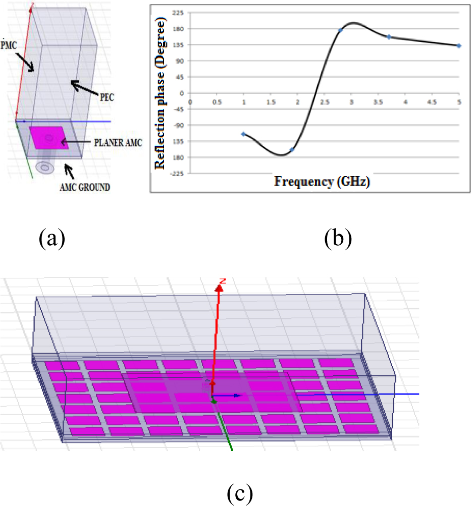
Figure 8: AMC unit cell. (a) Simulation setup in HFSS. (b) Reflection phase characteristic. (c) Overall view of the proposed antenna on AMC in HFSS.
Wearable antennas are explicitly designed to be worn close to the physical body, and the SAR is used to address the dangers posed to the humanbody by wearable specialized gadgets [47]. SAR is a critical boundary for determining the amount of electromagnetic field consumed by human tissues [48].
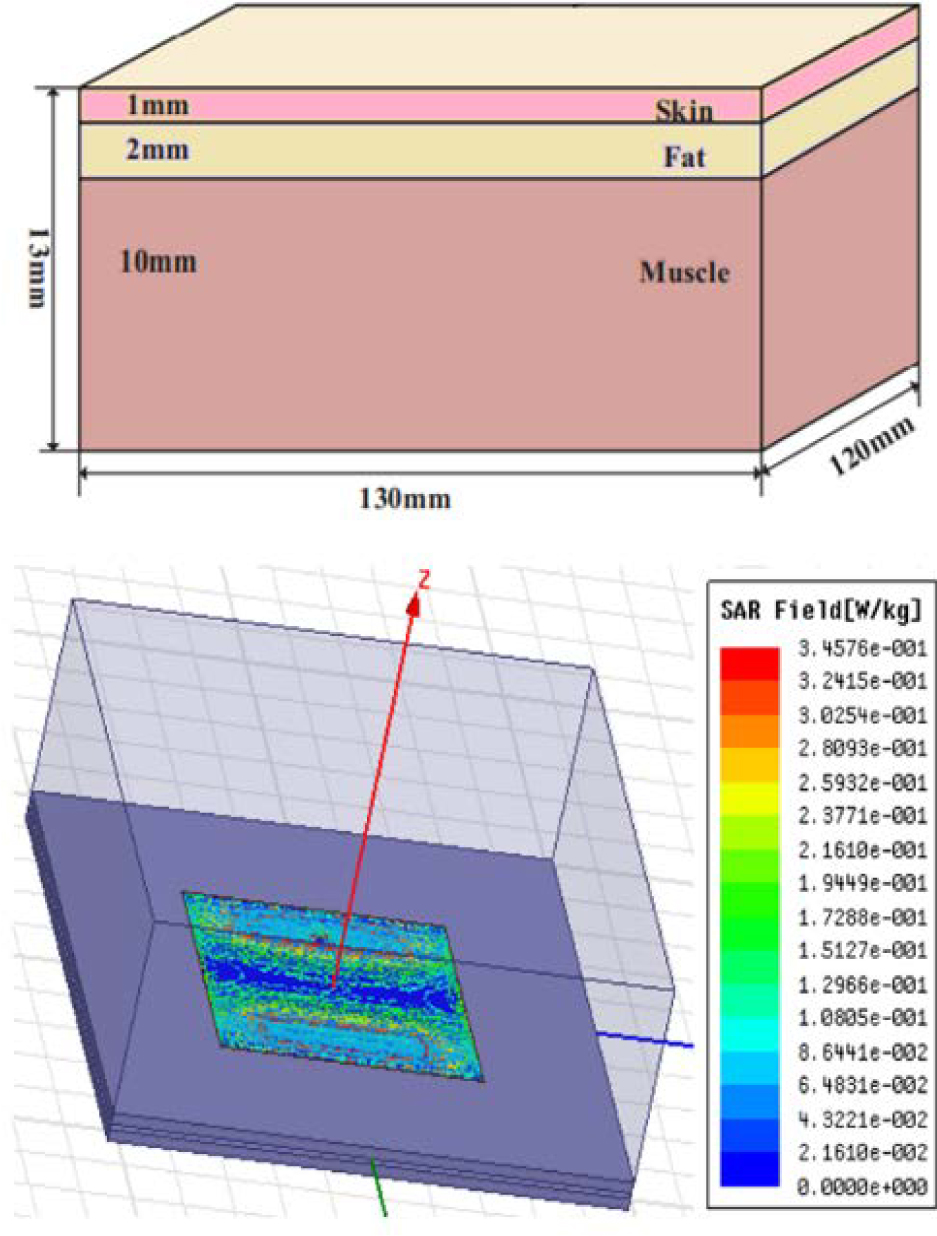
Figure 9: SAR distributions of the proposed antenna on AMC in HFSS.
Figure 9 simulates the basic model of human tissues [53] with their electrical properties, relative permittivity (), conductivity (), mass density () and thickness (d), consisting of skin ( = 38.0067, = 1.184, = 1001 kg/m, d = 1 mm), fat ( = 10.8205, = 0.58521, = 900 kg/m, d = 2 mm), and muscle ( = 55, = 1.437, = 1006 kg/m, d = 10 mm) with a size of 130 mm 120 mm 13 mm and SAR distributions at 2.4 GHz with an input power of 0.1 W. The antenna is positioned at a height of 2 mm from the tissue surface. From the simulated SAR distributions, the peak 1 g SAR value for patch alone is 4.08 W/kg. Then again, the peak 1 g SAR value for patches on AMC is 1.272 W/kg (3.4576e). From the outcome, it tends to be seen that the most extreme SAR regard diminishes essentially with the presentation of the AMC plane and, furthermore, the SAR constraint is fulfilled with a value that is well-below the acceptable limit. Both the patch and the substrate have been cut and stuck manually. Moreover, feeding cable losses were not considered in the simulation.
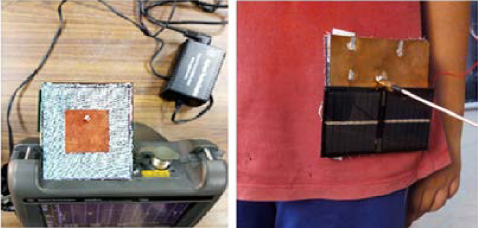
Figure 10: Proposed wearable antenna measurement setup.
In this study, surveys for both free space and on-body surroundings are considered. The performance of the man-made proposed antenna placed on the flat surface of the physical body should be studied to demonstrate whether it meets the sensible applicationnecessities or not. Each layer of the physical body has its own dielectric characteristics that additionally rely on the frequency. The proposed antennas are meant to be worn around the torso area; hence they are positioned on the abdomen. The proposed antenna was tested through an Agilent-N5230A vector network analyzer associated with the standard calibration, and the S-parameter measurement arrangement is displayed in Figure 10.
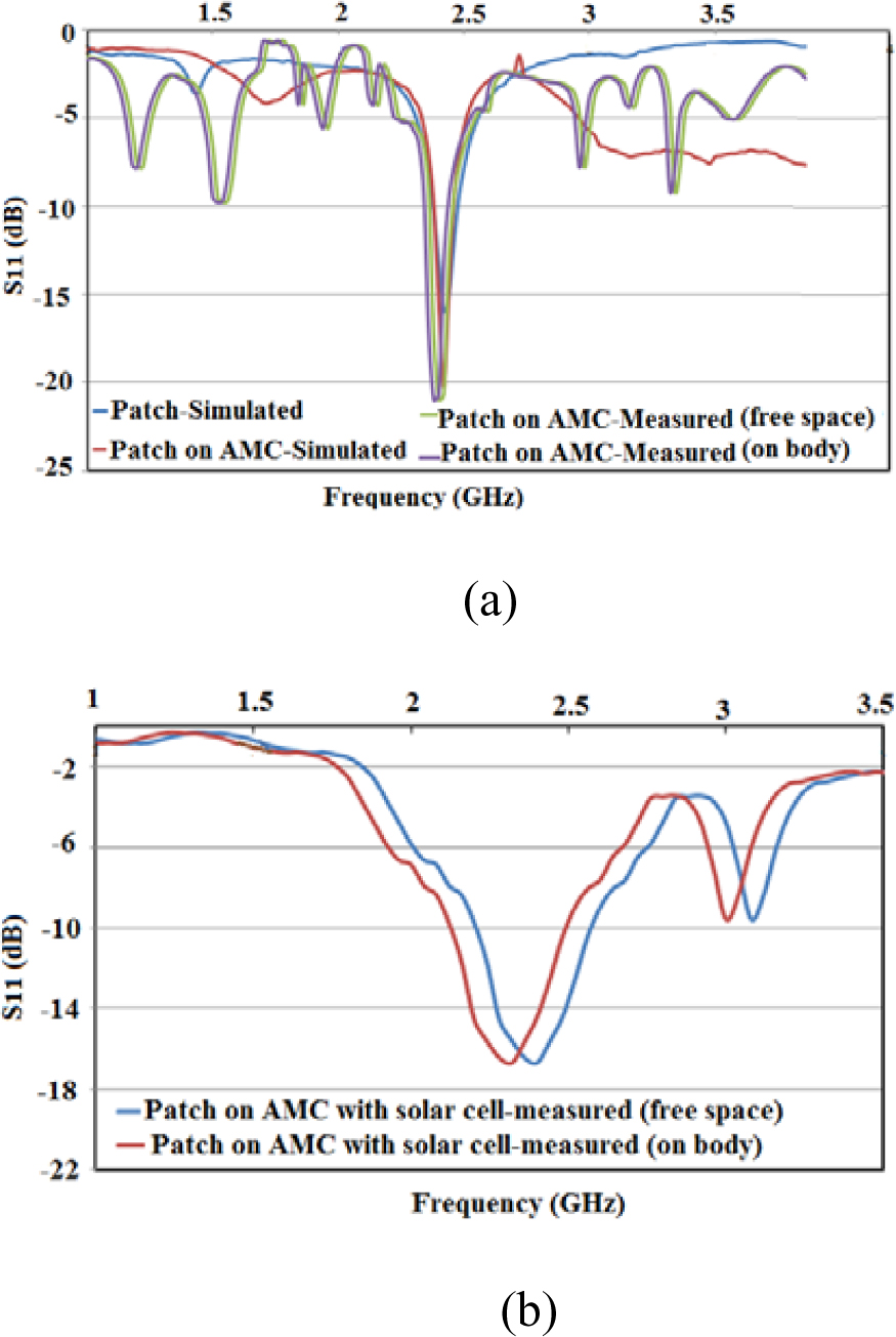
Figure 11: S versus frequency: (a) free space environment; (b) on-body environment.
The simulated and measured values of the S and VSWR concerning the frequency are shown in Figures 11 and 12 in free space and in the body environment. The simulated S and VSWR of the patch antenna on the AMC plane with the copper ground at 2.42 GHz are 20.26 dB and 1.23 with an impedance bandwidth of 3.3% from 2.38–2.46 GHz. By considering the free space environment, the measured S and VSWR of the patch antenna on the AMC plane with the copper ground at 2.4 GHz are 21 dB and 1.19 with an impedance bandwidth of 4.16% from 2.36–2.46 GHz. On the other hand, the measured S and VSWR of the same patch antenna on the AMC plane with partially copper-aided solar cells ground plane at 2.4 GHz is 16.695 dB and 1.06 with an impedance bandwidth of 13.33% from 2.24–2.56 GHz.
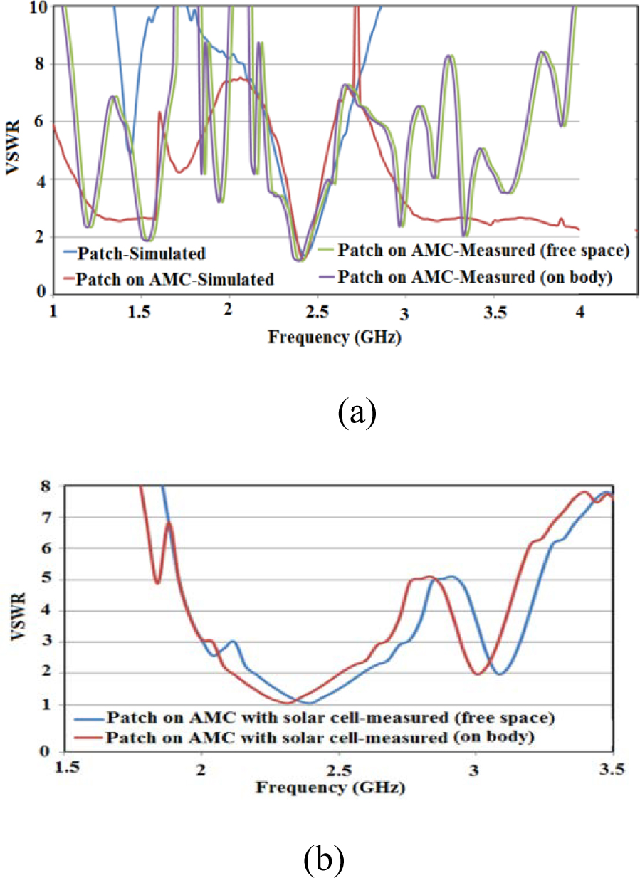
Figure 12: VSWR versus frequency: (a) free space environment; (b) on-body environment.
For on-body consideration, the proposed patch antenna on the AMC plane with the copper ground plane resonates over the 2.34–2.44 GHz band (impedance bandwidth of 4.2%) and also the same patch antenna on the AMC plane with a partially copper-aided solar cell ground plane resonates over the 2.16–2.48 GHz band (impedance bandwidth of 13.79%) with VSWR less than 2. Figures 11 and 12 show that S of the antenna encompasses a slight deviation, whereas the general performance of the antenna is largely the same as with the original antenna. It is often seen that the designed wearable antenna suffers less from the electrical characteristics of human tissues, and its performance is comparatively stable.
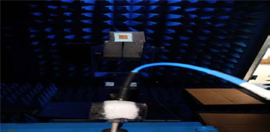
Figure 13: Photograph of the measurement environment: the anechoic chamber with standard horn antenna and proposed antenna.
The proposed antenna gain was measured overan anechoic chamber measurement setup and is shown in Figure 13. The radiation pattern of the simulated gains of the proposed antenna at 2.4 GHz is shown in Figure 14.
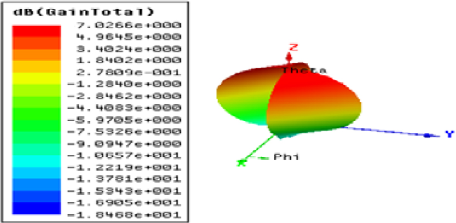
Figure 14: Simulated 3D gain radiation pattern of the proposed antenna.
The realized peak gain of the proposed patch antenna loaded with AMC under simulation is 7.02 dBi. The simulated antenna gain was enhanced from 4.51 dBi for the patch antenna to 7.02 dBi for the patch on the AMC reflector. From an application point of view, an AMC reflector can be evaluated by comparing antenna radiation features in the presence of an AMC reflector with and without the aid of solar cell ground.
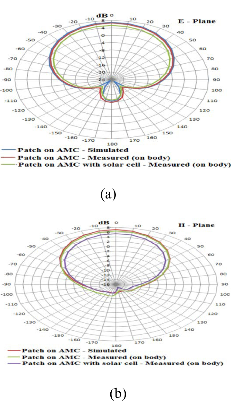
Figure 15: 2D radiation patterns of simulated and measured gain: (a) E-plane; (b) H-plane.
The far-field E-plane (YZ-plane) and H-plane (XZ-plane) radiation patterns at 2.4 GHz are shown in Figure 15 (a) and (b) based on simulation and measurement results. In the physical body environment, the measured peak gain of the proposed antenna on the AMC plane with copper ground and the same patch on the AMC with copper ground aided with solar cells is 6.53 dBi and 5.33 dBi, respectively.
The AMC loaded antennas have decreased side and back lobe radiation, as shown in Figure 15, and have good unidirectional radiation properties. When compared to the proposed antenna with copper ground, the proposed antenna with copper ground aided by solar cells emits the least amount of radiation in the broadside direction and has a gain along the antenna plane that is only a few decibels below the maximum. When such an antenna is placed on the human body, the antenna’s small rear lobe shows that very little energy is emitted into the tissue. Because of this property, the antenna is more robust to human body loading, making it an excellent fit for wearable applications.
On discussion of the effect of solar cells on AMC ground, the proposed antenna will not affect the radiation much and will only cause a minor deviation in gain due to the solar cells’ semiconductor nature. Another limitation on the discussion about the operation of the proposed antenna in the body environment is that the solar cells are aided on the ground plane of the AMC, on the external body side, and the antenna patch on the internal body side. As a result, the maximum radiation is directed at the human body, and its radiation gainperformance suffers slightly. This proposed design is useful for in-body and on-body communication. Meanwhile, the utilization of solar cells must be considered for its DC energy conversion performance when externally falling solar light hits the solar cells.
Table 2: Comparison with previous works
| Parameter/Ref. | Conducting parts | Substrate parts | Reflected plane/number of unit cells/size (mm) | No. of band | GaindBi | Band of operation (GHz) | 1 g aver. SAR W/kg | Applications |
| [36] | Shieldex conductivemetalized nylon (Zell) | Leather | EBG8 circular periodic100 100 | 1 | 0.75 | 5.7–5.87 | 1.21 | ISM band for on-body communication |
| [37] | Copper | PolyDimethylsiloxane | EBG2 340 32 | 1 | 2.1–5.6 | Center frequency 2.4 | 0.0536 | WBAN applications |
| [38] | Copper | Rogers RT/Duroid 5880 | Metasurface 2 2– | 2 | 4.544.71 | 3.2–3.5 3.9–4.3 | 0.1740.207 | WBAN communication |
| [40] | Copper | Rogers RO3003 | Metasurface 2 262 40 | 1 | 6.2 | 2.36–2.4 | 0.66 | Medical BAN devices |
| [41] | Nickel-copper-polyester | Felt | Metamaterial 7 7100 100 | 1 | 6 | 4.55–13 | 0.067 | UWB-WBANapplication |
| [44] | ShieldIt Super | Felt | AMC3 387 77 | 2 | 5.57.5 | 2.4–2.75.04–6.04 | - | Wi-Fi on-body applications |
| [46] | ShieldIt Super | Felt | AMC4 4100 100 | 2 | 2.50–4 | 2.455.04–5.93 | 0.04640.0232 | WLAN applications |
| [49] | ShieldIt | Fleece fabric | AMC6 4306 306 | 1 | 6.53 | 2.17–2.57 | 0.03(for10 g aver.) | Wearableapplications |
| [50] | ShieldIt | Felt (antenna)Denim (AMC) | AMC3 385 85 | 2 | - | 2.4–2.69 5.15–5.87 | - | Wi-Fi and the 4G-LTE applications |
| [51] | Copper | Pellon(antenna)RO3003 (AMC) | AMC4 4124 124 | 1 | 4.6 | 2.2–2.6 | 0.33 | ISM bandapplications |
| [52] | Zelt | FeltJeans Cotton | AMC2 342 63 | 2 | 7.149.9 | Center frequency2.45 & 5.8 | 0.340.27 | Wi-Fi applications |
| [53] | Copper | Polyimide | AMC2 266.8 66.8 | 1 | 7.47 | 2.27–2.76 | 0.15 | Medical BAN devices |
| The proposed antenna | Copper | Jeans fabric | AMC7 8101 96 | 1 | 5.33 | 2.16–2.48 | 1.272 | ISM band applications & DC energy conversion |
Table 3: Evaluation results of the proposed antenna
| Model | Band of operation (GHz) | Impedance bandwidth | VSWR | S(dB) | Gain total (dBi) |
| Patch sim. | 2.38–2.48 | 4.13% | 1.38 | 15.94 | 4.51 |
| Patch on AMC sim. | 2.38–2.46 | 3.3% | 1.23 | 20.26 | 7.02 |
| Patch on AMC meas. | 2.34–2.44 | 4.2% | 1.19 | 21 | 6.53 |
| Patch on AMC with solar cells meas. | 2.16–2.48 | 13.79% | 1.272 | 18.3 | 5.33 |
A small difference between the simulated and measured curves is examined. This is clarified by the vulnerability concerning the material substrate properties and the mechanical errors brought about by the manual manufacturing method with basic apparatuses. Note that utilizing machine dimensions or laser slicing does not lead to better outcomes because of the unavoidable irregularity of the antenna during practical operation. The most significant thing is that antenna performance, despite everything, satisfies the necessities for WLAN communication. SAR measurements and thermal impacts [48, 59] are used to examine the biological effects of the performing antenna. Due to lower permittivity at higher frequencies, there was a decline in biological effect as the resonant frequency increased. As a result, SAR is reduced, and the heat effect is also reduced. Electronic textiles, which are hybrid products that incorporate electrical functionality into textiles, must frequently resist washing operations in order to maintain textile usability. However, washability, which is critical for many electronic textile applications such as medical or sports due to cleanliness standards, is frequently insufficient. The elements that determine washing damage in textile integrated electronics, as well as common weak points, have not been substantially explored, making a targeted strategy to improve washability in electronic textiles problematic [60, 61].
The solar cell parameters, open circuit voltage (V) and short circuit current (I) were measured by concentrating the normal sun-based light on solar cells, embedding them with and without the antenna. From the measurements, the proposed solar cells carry a current of I = 100 mA with a voltage V = 8 V when none is integrated with the antenna. Nevertheless, the same solar cells are connected with an antenna; the measured I current and V voltage are 96 mA and 8 V, respectively. The voltage-current (VI) characteristics of solar cells integrated with and without antennas are shown in Figure 16. The power delivered by a solar cell is the product of current and voltage. If the multiplication is done point for point, for all voltages from short-circuit to open-circuit conditions, the power curve is obtained for a given radiation level. Of course, neither of these two conditions generates any electrical power, but there must be a point, called the “Knee” point, somewhere in between where the solar cells generate maximum power, P. The observed P of the solar cell without and with the antenna is 378 mW and 363.08 mW, which is a small decrease in maximum outputDC power of 14.92 mW and is also commonly acceptable.
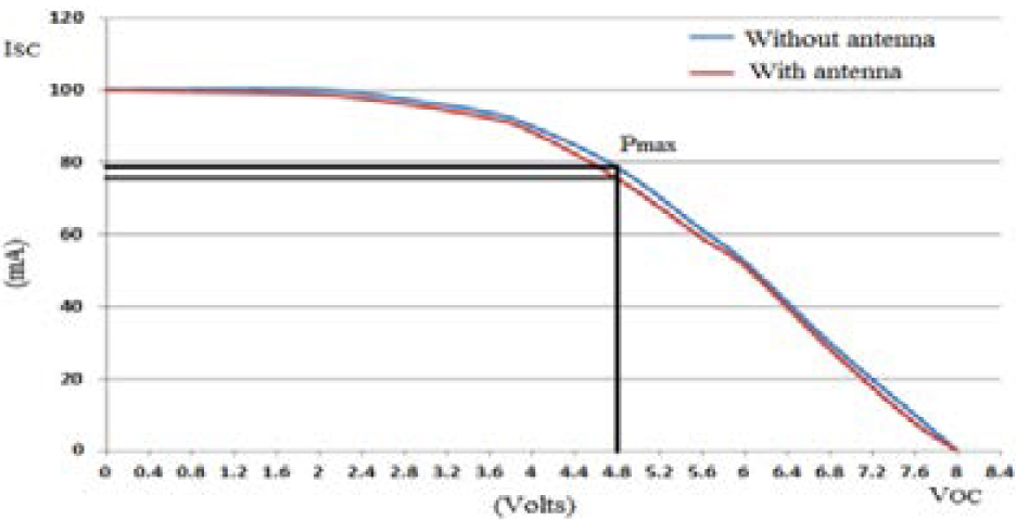
Figure 16: Solar cell VI characteristics with and without antenna.
Table 2 shows the novelty of the proposed antenna compared with several reported wearable antennas. The evaluation results in Table 3 indicate that the proposed antennas have a lower profile and operate in the ISM band used for green wearable wireless on-body and in-body communications with acceptable bandwidth.
IV. CONCLUSION
In this article, a textile patch antenna on the AMC surface stacked silicon solar cells partially with its copper ground is presented and tested for its performance. A technical viewpoint on the loading of the AMC with the antenna and also the RF behavior of solar cells by incorporating them into the AMC ground plane is elucidated. The improvement of radiation efficiency with a reduction in specific absorption rate levels is achieved over frequencies clustered around 2.4 GHz. The bending and crumbling tests on the proposed antenna are limited due to the brittle nature of solar cells stacked with the AMC ground plane. Currently, flexible solar cells are a research-level technology. In order for solar clothing to function at an optimal level, direct exposure to sunlight is required for very long periods. It is hoped that solar clothing will be able to charge phones, tablets, and GPS units for people who enjoy outdoor activities such as skiing, snowboarding, or hiking.
REFERENCES
[1] A. Maskooki, G. Sabatino, and N. Mitton, “Analysis and performance evaluation of the next generation wireless networks,” M. Simul. Comput. Netw. Syst. Methodol. Appl., vol. 21, pp. 601-627, Apr. 2015.
[2] N. F. M. Aun, P. J. Soh, A. A. Al-Hadi, M. F. Jamlos, G. A. E. Vandenbosch, and D. Schreurs, “Revolutionizing wearables for 5G: 5G technologies: Recent developments and future perspectives for wearable devices and antennas,” IEEE Microw. Mag., vol. 18, no. 3, pp. 108-124, May 2017.
[3] R. Dangi, P. Lalwani, G. Choudhary, I. You, and G. Pau, “Study and investigation on 5G technology: A systematic review,” Sensors, vol. 22, no. 1, Dec. 2021.
[4] R. K. Kanth, P. Liljeberg, H. Tenhunen, Y. Amin, Q. Chen, L. Zheng, and H. Kumar, “Quantifying the environmental footprint of rigid substrate printed antenna,” in Proc. 2012 IEEE Conf. Technol. Soc. Asia (T&SA), Singapore, pp. 27-29, Oct. 2012.
[5] R. K. Kanth, Q. Wan, H. Kumar, P. Liljeberg, Q. Chen, L. Zheng, and H. Tenhunen, “Evaluating sustainability, environment assessment and toxic emissions in life cycle stages of printed antenna,” Procedia Eng., vol. 30, pp. 508-513, Jan.2012.
[6] O. Boric-Lubecke, V. M. Lubecke, B. Jokanovic, A. Singh, E. Shahhaidar, and B. Padasdao, “Microwave and wearable technologies for 5G,” in Proc. 12th Int. Conf. Telecommun. Modern Satellite, Cable Broadcasting Services (TELSIKS), Nis, Serbia, pp. 183-188, 14-17, Oct. 2015.
[7] O. Galinina, H. Tabassum, K. Mikhaylov, S. Andreev, E. Hossain, and Y. Koucheryavy, “On feasibility of 5G-grade dedicated RF charging technology for wireless-powered wearables,” IEEE Wireless Commun., vol. 23, no. 2, pp. 28-37, Apr. 2016.
[8] K. N. Paracha, S. K. Abdul Rahim, P. J. Soh, and M. Khalily, “Wearable antennas: A review of materials, structures, and innovative features for autonomous communication and sensing,” IEEE Access, vol. 7, pp. 56694-56712, Apr. 2019.
[9] A. Desore and S. A. Narula, “An overview on corporate response towards sustainability issues in textile industry,” in Environment, Development and Sustainability: A Multidisciplinary Approach to the Theory and Practice of Sustainable Development, vol. 20, no. 4. Berlin, Germany: Springer, pp. 1439-1459, Aug. 2018.
[10] C. C. Zarakovitis, Q. Ni, and M.-A. Kourtis, “Enabling radioprotection capabilities in next generation wireless communication systems: An ecological green approach,” Trans. Emerging Telecommun. Technol., vol. 29, no. 10, pp. 1-21, Oct. 2018.
[11] A. Srivastava, M. S. Gupta, and G. Kaur, “Energy efficient transmission trends towards future green cognitive radio networks (5G): Progress, taxonomy and open challenges,” J. Netw. Comput. Appl., vol. 168, Oct. 2020.
[12] S. Vaccaro, J. R. Mosig, and P. de Maagt, “Making planar antennas out of solar cells,” Electron. Lett., vol. 38, no. 17, pp. 945-947, Aug. 2002.
[13] O. Yurduseven, D. Smith, N. Pearsall, and I. Forbes, “A solar cell stacked slot-loaded suspended microstrip patch antenna with multiband resonance characteristics for WLAN and WiMAX systems,” Prog. Electromagn. Res., vol. 142, pp. 321-332, Sep. 2013.
[14] O. Yurduseven and D. Smith, “Solar cell stacked dual-polarized patch antenna for 5.8 GHz band WiMAX network,” Electron. Lett., vol. 49, no. 24, pp. 1514-1515, Nov. 2013.
[15] M. Elsdon, O. Yurduseven, and X. Dai, “Wideband metamaterial solar cell antenna for 5 GHz Wi-Fi communication,” Prog. Electromagn. Res. C, vol. 71, pp. 123-131, Feb. 2017.
[16] S. V. Shynu, M. J. R. Ons, P. Mcevoy, J. A. Max, J. M. Sarah, and B. Norton, “Integration of microstrip patch antenna with polycrystalline silicon solar cell,” IEEE Trans. Antennas Propag., vol. 57, no. 12, pp. 3969-3972, Jun. 2009.
[17] S. V. Shynu, M. J. R. Ons, J. A. Max, and B. Norton, “Dual band a-Si:H solar-slot antenna for 2.4/5.2 GHz WLAN applications,” in Proc. IEEE 2009 3rd European Conference on Antennas and Propag., Berlin, Germany, pp. 408-410, Mar. 2009.
[18] M. J. R. Ons, S. V. Shynu, M. J. Ammann, S. J. Mccormack, and B. Norton, “Transparent patch antenna on a-Si thin-film glass solar module,” Electron. Lett., vol. 47, no. 2, pp. 85-86, Jan. 2011.
[19] O. O’Conchubhair, A. Narbudowicz, P. Mcevoy, and M. J. Ammann, “Circularly polarised solar antenna for airborne communication nodes,” Electron. Lett., vol. 51, no. 9, pp. 667-669, Apr. 2015.
[20] F. Nashad, S. Foti, D. Smith, M. Elsdon, and O. Yurduseven, “Ku-band suspended meshed patch antenna integrated with solar cells for remote area applications,” Prog. Electromagn. Res. C, vol. 83, pp. 245-254, Apr. 2018.
[21] T. N. S. Babu and D. Sivakumar, “Stepped slot patch antenna with copper ground plane and solar cell ground plane for future mobile communications,” Prog. Electromagn. Res. C, vol. 98, pp. 187-198, Jan. 2020.
[22] B. Naresh, V. K. Singh, and V. K. Sharma, “Integration of RF rectenna with thin film solar cell to power wearable electronics,” Int. J. Microw. Wireless Technol., vol. 13, no. 1, pp. 46-57, Feb. 2021.
[23] T. N. S. Babu and D. Sivakumar, “Patch antenna integrated on solar cells for green wireless communication: A feature oriented survey and design issues,” Int. J. RF Microw. Comput.-Aid. Eng., vol. 32, no. 1, pp. 1-29, Sep. 2021.
[24] S. Sankaralingam and B. Gupta, “Experimental results on HIPERLAN/2 antennas for wearable applications,” Prog. Electromagn. Res. C, vol. 25, pp. 27-40, Oct. 2011.
[25] R. Poonkuzhali, C. Alex Zachariah, and T. Balakrishnan, “Miniaturized wearable fractal antenna for military applications at VHF band,” Prog. Electromagn. Res. C, vol. 62, pp. 179-190, Mar. 2016.
[26] D. Ferreira, P. Pires, R. Rodrigues, and F. S. C. Rafael, “Wearable textile antennas-examining the effect of bending on their performance,” IEEE Antennas Propag. Mag., vol. 17, pp. 1045-9243, Jun. 2017.
[27] I. A. Mohamed, F. A. Mai, and A. S. Abd-El, “Novel electro-textile patch antenna on jeans substrate for wearable applications,” Prog. Electromagn. Res. C, vol. 83, pp. 255-265, Apr. 2018.
[28] I. Agbor, K. B. Dipon, and I. Mahbub, “A comprehensive analysis of various electro-textile materials for wearable antenna applications,” in Proc. 2018 Texas Symp. Wireless Microw. Circuits Syst. (WMCS), Waco, TX, USA, pp. 1-4,Apr. 5-6, 2018.
[29] S. Zhang, W. Whittow, R. Seager, A. Chauraya, and C. J. Vardaxoglou (Yiannis), “Non-uniform mesh for embroidered microstrip antennas,” IET Microw. Antennas Propag., vol. 11, no. 8, pp. 1086-1091, Feb. 2017.
[30] F. N. Mohd Hussin Ezzaty, P. J. Soh, M. F. Jamlos, H. Lago, and A. Al-Hadi Azremi, “Wideband microstrip-based wearable antenna backed with full ground plane,” Int. J. RF Microw. Comput.-Aid. Eng., vol. 29, no. 7, pp. 1-12, Mar. 2019.
[31] B. Sanz-Izquierdo, J. C. Batchelor, and M. I. Sobhy, “Button antenna on textiles for wireless local area network on body applications,” IET Microw. Antennas Propag., vol. 4, no. 11, pp. 1980-1987, Nov. 2010.
[32] S. J. Boyes, P. J. Soh Boyes, Y. Huang, G. A. E. Vandenbosch, and N. Khiabani, “On-body performance of dual-band textile antennas,” IET Microw. Antennas Propag., vol. 6, no. 15, pp. 1696-1703, Dec. 2012.
[33] E. F. Sundarsingh, S. Velan, M. Kanagasabai, K. S. Aswathy, C. Raviteja, and M. G. N. Alsath, “Polygon-shaped slotted dual-band antenna for wearable applications,” IEEE Antennas Wireless Propag. Lett., vol. 13, pp. 611-614,Mar. 2014.
[34] C. Mendes and C. Peixeiro, “A dual-mode single-band wearable microstrip antenna for body area networks,” IEEE Antennas Wireless Propag. Lett., vol. 16, pp. 3055-3058, Oct. 2017.
[35] S. Chilukuri and S. Gogikar, “A CPW-fed denim based wearable antenna with dual band-notched characteristics for UWB applications,” Prog. Electromagn. Res. C, vol. 94, pp. 233-245,Aug. 2019.
[36] J. Tak, Y. Hong, and J. Choi, “Textile antenna with EBG structure for body surface wave enhancement,” Electron. Lett., vol. 51, no. 15, pp. 1131-1132, Jul. 2015.
[37] G. Gao, R. Zhang, C. Yang, H. Meng, W. Geng, and B. Hu, “Microstrip monopole antenna with a novel UC-EBG for 2.4 GHz WBAN applications,” IET Microw. Antennas Propag., vol. 13, no. 13, pp. 2319-2323, Oct. 2019.
[38] B. Hazarika, B. Basu, and J. Kumar, “A multi-layered dual-band on-body conformal integrated antenna for WBAN communication,” AEU-Int. J. Electron. Commun., vol. 95, pp. 226-235, Oct. 2018.
[39] C. Wang, L. Zhang, S. Wu, S. Huang, C. Liu, and X. Wu, “A dual-band monopole antenna with EBG for wearable wireless body area networks,” Appl. Comput. Electromagn. Soc. J., vol. 36, no. 1, pp. 48-54, Jan. 2021.
[40] Z. H. Jiang, E. B. Donovan, E. S. Peter, and H. W. Douglas, “A compact, low-profile metasurface-enabled antenna for wearable medical body-area network devices,” IEEE Trans. Antennas Propag., vol. 62, no. 8, pp. 4021-4029, Aug. 2014.
[41] H. Yalduz, T. E. Tabaru, V. T. Kilic, and M. Turkmen, “Design and analysis of low profile and low SAR full-textile UWB wearable antenna with metamaterial for WBAN applications,” AEU-Int. J. Electron. Commun., vol. 126, no. 153465, Sep. 2020.
[42] E. Delihasanlar and A. H. Yuzer, “Wearable textile fabric based 3D metamaterials absorber in X-band,” Appl. Comput. Electromagn. Soc. J., vol. 35, no. 2, pp. 230-236, Feb. 2020.
[43] M. R. I. Faruque, M. T. Islam, and N. Misran, “Influence of SAR reduction in muscle cube with metamaterial attachment,” J. Microelectron. Electron. Compon. Mater., vol. 41, no. 3, pp. 233-237, Aug. 2011.
[44] M. Mantash, A. C. Tarot, S. Collardey, and K. Mahdjoubi, “Investigation of flexible textile antennas and AMC reflectors,” Int. J. Antennas Propag., vol. 2012, no. 236505, pp. 1-10, May2012.
[45] A. Alemaryeen and S. Noghanian, “AMC integrated textile monopole antenna for wearable applications,” Appl. Comput. Electromagn. Soc. J., vol. 31, no. 6, pp. 612-618, Jun. 2016.
[46] S. Yan, P. J. Soh, and A. E. Vandenbosch Guy, “Low-profile dual-band textile antenna with artificial magnetic conductor plane,” IEEE Trans. Antennas Propag., vol. 62, no. 12, pp. 6487-6490, Dec. 2014.
[47] C. K. Chou, H. Bassen, J. Osepchuk, Q. Balzano, R. Petersen, M. Meltz, R. Cleveland, J. C. Lin, and L. Heynick, “Radio frequency electromagnetic exposure: Tutorial review on experimental dosimetry,” Bioelectromagnetics, vol. 17, no. 3, pp. 195-208, Jan. 1996.
[48] V. Karthik and T. Rama Rao, “Investigations on SAR and thermal effects of a body wearable microstrip antenna,” Wireless Personal Commun., vol. 96, no. 7, Mar. 2017.
[49] K. Kamardin, A. R. M. Kamal, S. H. Peter, S. N. Asmawati, M. E. Jalil, and M. F. A. Malek, “Textile diamond dipole and artificial magnetic conductor performance under bending, wetness and specific absorption rate measurements,” Radio Eng., vol. 24, no. 3, pp. 729-738, Sep. 2015.
[50] M. Mantash, A. C. Tarot, S. Collardey, and K. Mahdjoubi, “Design methodology for wearable antenna on artificial magnetic conductor using stretch conductive fabric,” Electron. Lett., vol. 52, no. 2, pp. 95-96, Jan. 2016.
[51] A. Alemaryeen and S. Noghanian, “Crumpling effects and specific absorption rates of flexible AMC integrated antennas,” IET Microw. Antennas Propag., vol. 12, no. 4, pp. 627-635, Feb. 2018.
[52] A. Mersani, O. Lotfi, and J. M. Ribero, “Design of a textile antenna with artificial magnetic conductor for wearable applications,” Microw. Optical Technol. Lett., vol. 60, pp. 1343-1349,Jun. 2018.
[53] B. Yin, J. Gu, X. Feng, B. Wang, Y. Yu, and W. Ruan, “A low SAR value wearable antenna for wireless body area network based on AMC structure,” Prog. Electromagn. Res. C, vol. 95, pp. 119-129, Sep. 2019.
[54] N. I. Zaidi, M. T. Ali, N. H. A. Rahman, M. S. A. Nordin, A. A. S. A. Shah, M. F. Yahya, and H. Yon, “Analysis of different feeding techniques on textile antenna,” in Proc. 2019 Int. Symp. AntennasPropagation (ISAP), Xi’an, China, pp. 1-3, 27-30, Oct. 2019.
[55] S. K. Dargar and V. M. Srivastava, “Moisture content investigation in the soil samples using microwave dielectric constant measurement method,” Int. J. Elect. Comput. Eng., vol. 10, no. 1, pp. 704-710, Feb. 2020.
[56] S. Sankaralingam and B. Gupta, “Determination of dielectric constant of fabric materials and their use as substrates for design and development of antennas for wearable applications,” IEEE Trans. Instrum. Meas., vol. 59, no. 12, pp. 3122-3130,Dec. 2010.
[57] A. P. Feresidis, G. Goussetis, S. Wang, and J. C. Vardaxoglou, “Artificial magnetic conductorsurfaces and their application to low-profile high-gain planar antennas,” IEEE Trans. Antennas Propag., vol. 53, no. 1, pp. 209-215,Jan. 2005.
[58] G. A. Casula, G. Montisci, A. Fanti, G. Mazzarella, and P. Maxia, “Design of low-cost uniplanar AMC structures for UHF applications,” in Proc. IEEE Int. Symp. Antennas Propagation USNC/URSI National Radio Sci. Meeting, Vancouver, BC, Canada, pp. 1598-1599, Jul. 19-24, 2015.
[59] M. B. Lodi, G. Muntoni, A. Ruggeri, A. Fanti, G. Montisci, and G. Mazzarella, “Towards the robust and effective design of hyperthermic devices: Improvement of a patch antenna for the case study of abdominal rhabdomyosarcoma with 3D perfusion,” IEEE J. Electromagn., RF Microw. Med. Biol., vol. 5, no. 3, pp. 197-205, Sep. 2021.
[60] F. Andriulli, “Washable Antennas? Be Careful While Doing Laundry! [Editor’s Comments],” IEEE Antennas Propagation Mag., vol. 63, no. 4, pp. 4-4, Aug. 2021.
[61] J. Pei, J. Fan, and R. Zheng, “Protecting wearable UHF RFID tags with electro-textile antennas: The challenge of machine washability,” IEEE Antennas Propagation Mag., vol. 63, no. 4, pp. 43-50, Aug. 2021.
BIOGRAPHIES

Suresh Babu T. Naganathan received the B.E. degree in Electronics and Communication Engineering from Madurai Kamaraj University, India, in 1997 and the M.E. degree in Power Electronics and Drives from Anna University, India, in 2009, respectively. He is currently working as an Assistant Professor in the Department of Electronics and Communication Engineering at Adhiparasakthi Engineering College, Tamilnadu, India. His research interests include those in the areas of Electromagnetics, Antenna design and Wave Propagation.

Sivakumar Dhandapani received the B.E. degree in Electronics and Communication Engineering from the University of Madras, India, in 1995, the M.E. degree in Process Control and Instrumentation from Annamalai University, India, in 2002, and the Ph.D. degree in Faculty of Information and Communication from Anna University, India, in 2010, respectively. He is now a Professor at Easwari Engineering College in Chennai, India, in the Department of Electronics and Communication Engineering. His research interests include those in the areas of MANET, Wireless Sensor Networks, Mobile Computing, and Network Security.
ACES JOURNAL, Vol. 37, No. 5, 576–587.
doi: 10.13052/2022.ACES.J.370507
© 2021 River Publishers