Research on EBE-FEM Parallel Algorithm Combined with Fast Color Marking Method Based on CUDA Platform
Xvdong Ren, Xiuke Yan, Jinpeng Lan, Ziyan Ren, and Yanli Zhang
School of Electrical Engineering
Shenyang University of Technology, Shenyang, 110870, China
yanxke@126.com
Submitted On: April 20, 2021; Accepted On: August 22, 2021
Abstract
The element-by-element finite element method (EBE-FEM) parallel algorithm has been realized on Compute Unified Device Architecture (CUDA) platform in this paper. An improved fast color marking method (FCM) combined with tabu search algorithm is proposed to solve the problem that the elements sharing a node wait for accessing the same memory space in parallel computation. The elements in the same color can be processed at the same time without waiting. This method can get more even color grouping faster than the classical coloring method (CCM). Combining it with the EBE parallel algorithm can achieve faster element-level operations. The validity and accuracy of the method has been verified by comparing the computed results with the analytical solution of the magnetic field produced by the solenoid. The parallel program is applied to analyze the main magnetic field of a single-phase transformer, which shows higher speedup performance.
Index Terms: EBE-FEM, parallel computation, fast color marking, element grouping.
I INTRODUCTION
Large-scale numerical calculation is usually involved in electromagnetic field analysis of large power equipment. It is difficult to obtain accurate and reasonable results by traditional serial finite element method (FEM) [1]. In recent years, parallel finite element methods and advanced computing platforms are developed and applied to numerical computation [2]. The traditional FEM realizes parallel computing by using Internet resources and cloud computing, splitting the program into multiple subprograms, which are computed simultaneously by multiple processors and returned to the terminal. In order to realize the complete parallel calculation of FEM, it is necessary to change the solution process of traditional FEM and add parallel algorithm into it. The element-by-element finite element method (EBE-FEM) is different from the traditional FEM [3, 4]. It does not form the global system matrix, solves the equation for each element, which can save the memory storage space and perform the solving process in parallel. The operations of each element are independent of each other, so it is easy to achieve parallelism between elements [5, 6]. The EBE-FEM is a method which transforms a highly memory dependent problem to a massively computational dependent one, the latter can be parallelized efficiently.
Compute Unified Device Architecture (CUDA) is a CPU + GPU heterogeneous computing platform, in which GPU is one of the newest types of parallel processors [7], its multi-core nature can fully exploit the parallelism of EBE-FEM. When implementing parallel computation of EBE-FEM on CUDA, to avoid race conditions, different threads cannot access the same memory space simultaneously. Generally, two methods have been used to solve this problem. One is “atomic operation,” on the early Nvidia GPU architectures such as Fermi, the storage space is protected and only one thread is allowed to access, which will affect the parallel efficiency of the algorithm [8]. On new architectures such as Kepler, these operating instructions have the “fire-and-forget” semantics and can be returned immediately. The conflict resolution is the responsibility of the cache system [9]. Another method is coloring [10, 11]. The elements with the common node have been given different colors to achieve the purpose of grouping. Elements in different colors are not calculated at the same time. The coloring result is repeatable, because each run will produce the same sequence of operations with the same round-off error accumulation, which is impossible for atomic addition. Different color grouping methods have different processor resource utilization, and the grouping results are also different [12].
In the classical coloring method (CCM), color A is marked first by traversing all elements, then mark color B [13, 14], only one color is marked in one traversal process. It introduces a lot of nested loops, which makes it run slowly and unevenly grouped. While the coloring efficiency and the grouping rationality will directly affect the calculation efficiency of EBE-FEM parallel algorithm. The fast color marking method (FCM) colors the elements sequentially, and all the elements need to be traversed only once. The FCM can obtain even grouping of elements quickly, and it has been used for element coloring in traditional FEM. However, all nodes still need to be traversed once when coloring an element, which leads to insufficient efficiency, especially for dealing with large-scale meshes.
In this paper, the parallel computation of EBE-FEM for engineering electromagnetic field analysis is implemented on CUDA platform. An optimized fast color marking method (OFCM) which combines FCM with tabu search algorithm is proposed to improve computational efficiency. The magnetic field produced by solenoid and single-phase transformer have been analyzed by EBE-FEM combined with FCM and OFCM respectively. The results have been compared and discussed. The corresponding FEM programs are developed in C++ language.
II METHOD DESCRIPTION
A EBE-FEM parallel algorithm based on CUDA
Using FEM, the Maxwell electromagnetic field equations can be discretized as linear equations
| (1) |
where A is the global coefficient matrix, x is the vector of unknowns, b is the right-hand vector.
The EBE establishes the relationship between the local quantity and the global quantity through the transition matrix
| (2) |
where Q is the connection matrix between the coefficient matrix of the element e and the global coefficient matrix, E is the set of elements. (1) can be transformed as
| (3) |
| (4) |
where A is the matrix of element coefficients, which is directly obtained by finite element analysis. b is the element right-hand.
The main operation of CG method is the inner product of vectors, which are appropriate to realize parallel computation. Therefore, CG method has been used to solve the equations of EBE-FEM.
| (5) |
where r is global residual vector. In EBE-FEM, it can be expressed by,
| (6) |
where r is the element residual.
In CG, (r, r) and (p, Ap) are the most important calculations, occupying the most computer resources. In EBE-FEM, the inner product can be calculated on each element as
| (7) |
| (8) |
| (9) |
where adj(e) represents the adjacent element which share the common node with element e.
| (10) |
| (11) |
where p is global direction vector, p is the local element direction vector.
The equations obtained by discretization are ill-conditioned, which causes the convergence speed of the CG method to slow down or even not converge. In order to improve the convergence, the Jacobi preconditioned (JP) technology is applied to EBE-CG. The Jacobi preconditioner is a simple preconditioned method with good parallelism [15]. The Jacobi preconditioned factor consists of the diagonal elements of the coefficient matrix and does not increase memory and communication time. The Jacobi preconditioned factor can be calculated on each element as
| (12) |
where m is the Jacobi preconditioned factor.
The computation for all the elements will be executed in parallel through thousands of threads on CUDA platform.
B Classical coloring method
Coloring problem is a branch of graph theory problems in mathematics. The coloring method needs to group the elements as even as possible with as few colors as possible [16]. The number of colors is not the smaller the better, it should meet the needs of the current calculation. CCM is shown in Algorithm 1.
Algorithm 1: Classical coloring method
1: Use a new color.
2: Get the nodes of the adjacent element.
3: Get all the element numbers associated with the nodes.
4: Get the color numbers of adjacent elements.
5: If the current color is not used for adjacent elements, provide it for the current element. Otherwise, return to 2.
6: If all elements are colored, stop. Otherwise, return to 1.
The CCM can obtain crude element grouping, but the grouping is uneven; there are “rich” groups containing too many elements and “poor” groups with too few elements. The grouping diagram is shown in Figure 1.
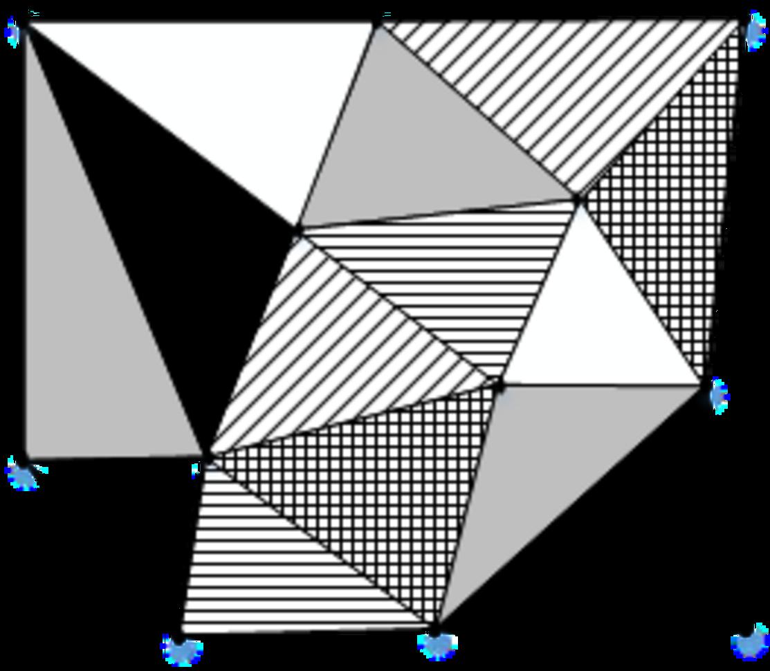
Fig. 1. A 2D coloring group diagram.
These groups require additional operation to make them more even. In addition, the CCM has the problem of excessive nesting of loops. These problems make the coloring time long and efficiency low.
C Fast color marking method
To solve the problems of the CCM, the FCM is proposed to get more even groups faster. The FCM is as follows:
Algorithm 2: Fast color marking method
1: Get the nodes of the current element.
2: Get all the element numbers associated with the nodes.
3: Get the color numbers of adjacent elements.
4: Provide the current element with the smallest number among the unused color numbers of adjacent elements.
5: If all elements are colored, stop. Otherwise, return to 1.
The FCM colored the elements sequentially, it reduces the loop nesting existed in CCM and makes the grouping more uniform.
D Optimized fast color marking method
When using FCM, all nodes need to be traversed once and the color numbers of adjacent elements also need to be retrieved once, which greatly increases the number of instructions to be executed.
In this paper, tabu search algorithm is introduced into FCM to improve grouping efficiency. A new array is set as a tabu table, in which the information of the elements that share the same nodes have been recorded as tabu object, and then marks the color of the current element, which can avoid repeated searches for nodes and the color serial. After optimization, the number of instructions has been reduced greatly, while the memory occupied by the new array is very small, therefore, the execution speed of the program can be improved obviously.
OFCM simplifies the looping process and logic judgment in FCM by introducing new arrays to record key information, the coloring process has been speeded up significantly. The optimized coloring algorithm can also be applied to face shading, edge shading, or vertex shading. Algorithm 3 shows the OFCM. The mathematical model of OFCM can be expressed as,
| (13) |
| (14) |
where C is the set of colors.
Algorithm 3: Optimized fast color marking method
1: Get the nodes of the current element.
2: Get all the element numbers associated with the nodes.
3: Create an array A to record the color of the current element, and retrieve the color numbers of adjacent elements from array A.
4: Provide the current element with the smallest number among the unused color numbers of adjacent elements.
5: Record the color of the current element in array A.
6: If all elements are colored, stop. Otherwise, return to 1.
Three coloring methods have been researched and programmed in this paper, a set of meshes has been colored by them respectively. The results are shown in Table 1.
Table 1: Comparison of three coloring methods
| Method | Elements | Nodes | Coloring | Colors |
| times (ms) | used | |||
| OFCM | 24106 | 12260 | 7634 | 7 |
| FCM | 24106 | 12260 | 19028 | 7 |
| CCM | 24106 | 12260 | 41358 | 8 |
From Table 1, it can be seen that the OFCM saves the execution time greatly, OFCM and FCM use less colors than CCM. Moreover, the grouping uniformity of OFCM and FCM is much higher than that of CCM. The number of elements in each group is about 3500 for FCM and OFCM, while the number of elements in each group varies greatly for CCM, ranging from 100 to 12,000. Based on the above results, in the following calculation examples, only FCM and OFCM are compared and discussed, and CCM is no longer used.
E Parallel EBE-FEM combined with OFCM
For EBE-FEM algorithm, the iterative solving process is performed for each element, and all elements can be solved at the same time by GPU. The local vector is pre-calculated and stored in memory. However, when the local element residual vector r and the vector m are accumulated in Jacobi preconditioner, if there are common nodes between adjacent elements, the access conflict will occur. Access conflict will reduce the calculation efficiency and even make calculation errors. After the coloring method divides the elements with common nodes into different groups, the element vectors of all elements in a group can be calculated simultaneously by EBE-FEM. In this way, access conflicts and calculation errors can be avoided, and complete parallelism within the group can be achieved. The loops between groups are still serial. The coloring process is executed by the CPU, and the EBE-FEM computing process is executed by the GPU, in which one element is processed by one thread.
The combination part of EBE and OFCM is shown in Algorithm 4.
Algorithm 4: The combination part of EBE and OFCM
1: for all colors c do // compute m
2: for do
3: M diag(e)
4:
5: end for
6: end for
7: for do
8: mm+M
9: end for
10: solve mzr
11: for all colors c do // compute r
12: for do
13: Z r
14:
15: end for
16: end for
17: for do
18: z z+Z
19: end for
III APPLICATION AND ANALYSIS
The proposed method has been applied to analyze the magnetic field produced by a solenoid and a single-phase power transformer. All the programs have been developed in C++. The computations have been carried out on a heterogeneous CUDA platform with a quad-core Intel i7-6700 CPU and an NVIDIA GTX 965m GPU.
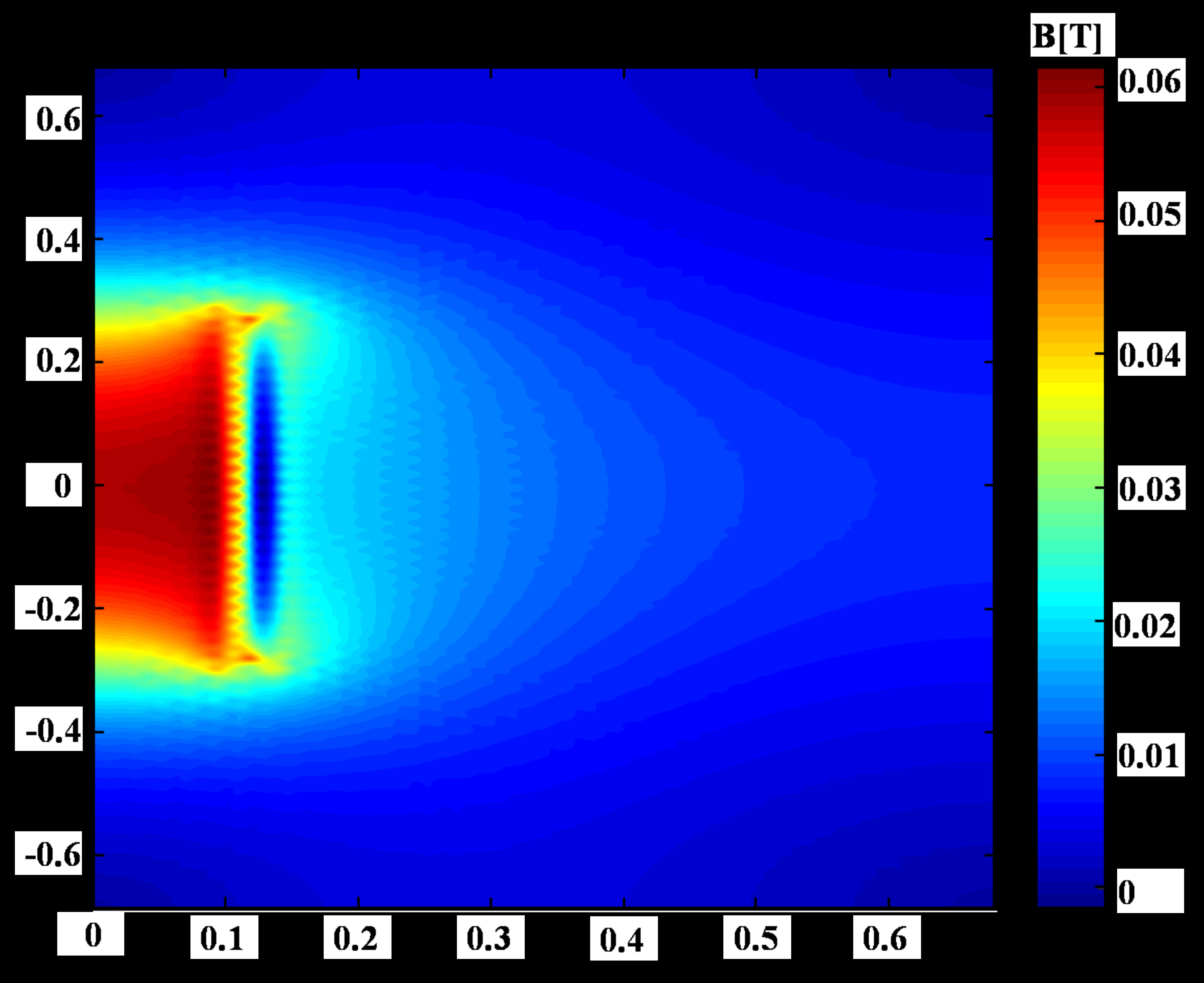
Fig. 2. The magnetic field distribution of the solenoid.
A Calculation and comparison of solenoid magnetic field
In order to verify the validity and accuracy of the algorithm and program, the magnetic field of a solenoid has been analyzed by the parallel EBE-FEM combining the OFCM and the FCM respectively. According to Biot–Savart Law, the analytical solution of the magnetic field at the points on the central axis can be calculated by
| (15) |
where is the permeability in vacuum, n is the number of turns, I is the current, R is the radius of the solenoid.
A rectangle region is set as the solution domain, and the magnetic field distribution is shown in Figure 2. Comparing the calculation results on the central axis of the solenoid with the analytical solution, the relative errors can be determined. The maximum relative errors are showed in Table 2.
It can be seen from Table 2 that the proposed method is valid and accurate, the OFCM is more efficient than FCM. The serial EBE-FEM only runs on the CPU without parallel computing and element coloring. The results show that the algorithm proposed in this paper has more advantages in calculation efficiency. The coloring algorithm does not change the calculation process and input variables of the EBE-FEM, the difference of relative errors is produced by the round-off error of the computer.
B Magnetic field in single-phase transformers
EBE-FEM parallel algorithm combined with different coloring methods have been investigated and applied to calculate the magnetic field produced by single-phase DSP-241000kVA/500kV transformer. The secondary side of the transformer is opened and the primary side is excited by rated current. The model of the transformer is shown in Figure 3. The model is subdivided into a triangular mesh, as shown in Figure 4.
Table 2: Calculated results of EBE method with different coloring method
| Method | Elements | Nodes | Coloring | Execution | Max relative |
| times (ms) | time (ms) | error (%) | |||
| OFCM+EBE | 4260 | 2224 | 227 | 2562 | 4.51 |
| FCM+EBE | 4260 | 2224 | 534 | 3008 | 4.43 |
| Serial EBE | 4260 | 2224 | 0 | 6441 | 4.50 |
Fig. 3. The model of the single-phase transformer.
Fig. 4. The mesh of the single-phase transformer.
Fig. 5. The magnetic field distribution of the transformer.
Fig. 6. The magnetic lines of transformer.
The distribution of the magnetic flux density and the magnetic lines are shown in Figures 5 and 6.
The calculation results of EBE-FEM combined with different coloring methods are shown and compared in Table 3. From Table 3, it can be seen that the coloring time of OFCM is twice faster than that of FCM. The larger scale mesh is involved, the higher efficiency can be obtained. The number and uniformity of the groups obtained by two coloring methods are similar, which can be seen from the similar calculation time of EBE-FEM.
Table 3 Calculated results of EBE method with different coloring method
| Test | Elements | Nodes | Coloring | Computation time | ||
| case | time (ms) | of EBE-FEM | ||||
| OFCM | FCM | OFCM | FCM | |||
| 1 | 11,443 | 5860 | 1862 | 4269 | 5704 | 5755 |
| 2 | 19,328 | 9848 | 5971 | 12,267 | 11,776 | 11,670 |
| 3 | 40,816 | 20,685 | 24,642 | 55,691 | 27,173 | 28,015 |
| 4 | 61,390 | 31,028 | 56,019 | 122,850 | 45,783 | 45,616 |
| 5 | 171,338 | 86,223 | 275,698 | 702,756 | 82,900 | 83,387 |
IV CONCLUSION
In this paper, the EBE-J-PCG method has been implemented in parallel on CUDA platform, an optimized fast color marking method is proposed to solve the access conflict in parallel computation. The OFCM can use less colors to get even grouping in the least coloring time, and even and reasonable color grouping is important for large-scale EBE parallel computing. The OFCM can be applied to face shading or vertex shading.
ACKNOWLEDGMENT
This work is supported in part by the National Natural Science Foundation under Grant 51777128.
References
[1] M. Macedonia, “The GPU enters computing’s mainstream,” IEEE Computer, vol. 36, no. 10, pp. 106-108, Oct. 2003.
[2] N. Godel, N. Nunn, T. Warburton, and M. Clemens, “Accelerating multi GPU based discontinuous Galerkin FEM computations for electromagnetic radio frequency problems,” Applied Computational Electromagnetics Society (ACES) Journal, vol. 25, no. 4, pp. 331-338, Apr. 2010.
[3] T. Hughus, I. Levit, and J. Winget, “An element-by-element solution algorithm for problems of structural and solid mechanics,” Computer Methods in Applied Mechanics and Engineering, vol. 36, no. 2, pp. 241-254, Feb. 1983.
[4] W. Dongyang, Y. Xiuke, T. Renyuan, X. Dexin, and R. Ziyan, “Parallel realization of element by element analysis of eddy current field based on graphic processing unit,” Applied Computational Electromagnetics Society (ACES) Journal, vol. 33, no. 2, pp. 168-171, Feb. 2018.
[5] C. Cecka, A. J. Lew, and E. Darve, “Assembly of finite element methods on graphics processors,” International Journal for Numerical Methods in Engineering, vol. 85, no. 5, pp. 40-669, Aug. 2011.
[6] Z. Yan, Y. Xiuke, R. Xvdong, W. Sheng, and W. Dongyang, “Parallel implementation and branch optimization of EBE-FEM based on CUDA platform,” Applied Computational Electromagnetics Society (ACES) Journal, vol. 35, no. 6, pp. 595-600, Jun. 2020.
[7] Y. Jararweh, M. Jarrah, A. Bousselham, and S. Hariri, “GPU-based Personal Supercomputing,” Proceedings of the 2013 IEEE Conference on Applied Electrical Engineering and Computing Technologies (AEECT), Amman, Jordan, Dec. 2013.
[8] I. Kiss, S. Gyimothy, Z. Badics, and J. Pavo, “Parallel Realization of the Element-by-Element FEM Technique by CUDA,” IEEE Transactions on Magnetics, vol. 48, no. 2, pp. 507-510, Feb. 2012.
[9] M. Kronbichler and K. Ljungkvist, “Multigrid for matrix-free high-order finite element computations on graphics processors,” ACM Transactions on Parallel Computing, vol. 6, no. 1, pp. 3-34, May 2019.
[10] G. F. Carey, E. Barragy, R. Mclay, and M. Sharma, “Element-by-element vector and parallel computa-tions,” Communications in Numerical Methods in Engineering, vol. 4, no. 3, pp. 299-307, 1988.
[11] K. Kormann and M. Kronbichler, “Parallel finite element operator application: graph partitioning and coloring,” IEEE Seventh International Conference on E-Science, Dec. 2011.
[12] A. Czumaj, K. Jansen, M. Friedhelm, and I. Schiermeyer, Algorithmic Graph Theory, Cambridge University Press, 1985.
[13] D. Komatitsch, D. Michea, and G. Erlebacher, “Porting a high-order finite-element earthquake modeling application to NVIDIA graphics cards using CUDA,” Journal of Parallel and Distributed Computing, vol. 69, no. 5, pp. 451-460, Jan. 2009.
[14] U. Kiran, D. Sharma, and S. Singh Gautam, “GPU-warp based finite element matrices generation and assembly using coloring method,” Journal of Computational Design and Engineering, vol. 4, no. 4, pp. 705-718, Nov. 2018.
[15] Y. Xiuke, H. Xiaoyu, W. Dongyaong, X. Dexin, B. Baodong, and R. Ziyan, “Research on preconditioned conjugate gradient method based on EBE-FEM and the application in electromagnetic field analysis,” IEEE trasactions on Magnetics, Jan. 2017.
[16] G. Chunlei and T. Hubing, “Development and application of a fast multipole method in a hybrid FEM/MoM field solver,” Applied Computational Electromagnetics Society (ACES) Journal, vol. 19, no. 3, pp. 126-134, Nov. 2004.
Biographies

Xvdong Ren Mr. Ren received a B.S degree in electrical engineering from Shandong Jianzhu University, China, in 2018. Currently studying at Shenyang University of Technology, studying for a Ph.D. in electrical engineering, and his research direction is numerical analysis and optimization of engineering electromagnetic fields.

Xiuke Yan (correspondence author) Ms. Yan received her B.S degree, M.S degree, and Ph.D. degree in electrical engineering from Shenyang University of Technology, China, in 1996, 1999, and 2005, respectively. She is currently a professor in Shenyang University of Technology. Her research interests include numerical analysis of coupled field and optimization design of electrical equipment, parallel algorithm research of finite element method.
ACES JOURNAL, Vol. 36, No. 10, 1281–1287.
doi: 10.13052/2021.ACES.J.361003
© 2021 River Publishers