Investigation of Electromagnetic Exposure of WPT Coil to Human Body Based on Biological Electromagnetic Safety Assessment
Hongyan Sun1, Shiliang Hou2, Yang Zhao3, Wei Yan3, and Yongji Wu3
1Nanjing Normal University Taizhou College
Taizhou, Jiangsu, 225300, China
2State Grid Shandong Maintenance Company
Jinan, Shandong, 250118, China
nnuhsl@163.com
3School of Electrical and Automation Engineering
Nanjing Normal University, Nanjing, Jiangsu, 210097, China
Submitted On: May 13, 2021; Accepted On: August 28, 2021
Abstract
When the wireless power transmission (WPT) system of electric vehicle (EV) is working, the leakage of high frequency electromagnetic field (EMF) to the non-working area will be a threat to human safety. According to SAE J2954 standard, the coupling coils modeling of WPT and car shell modeling are established. WPT’s bit-directional guidance technology and deviation correction control strategy are given. According to the harm degree of SAR, power density P, current density J, and magnetic induction intensity B to human body when the human model is in different positions of standing, lying, and sitting, the comprehensive harm index of electromagnetic radiation is creatively proposed to assess the electromagnetic radiation hazard of EV. Field circuit co-simulation helps us to study the bio-electromagnetic safety of WPT in vehicle environment. A human exposure EMF joint test system is designed and made to measure vehicle’s surrounding EMF. Through simulation and experimental verification, WPT coil’s electromagnetic exposure level to the human body inside the EV meets the requirements of ICNIRP, the EMF at the ankle outside the EV exceeds the standard and needs to be protected.
Index Terms: electric vehicle wireless power transmission (EV WPT), bio-electromagnetic safety assessment, comprehensive hazard index, human body model, field circuit co-simulation, electromagnetic exposure.
I. INTRODUCTION
With the improvement of people’s environmental awareness and the deepening of energy conservation and emission reduction ideas, electric vehicles (EVs) represent the development direction of the world automobile industry [1]. Wireless power transmission (WPT) technology does not need wires or other physical contacts. By converting electric energy into high-frequency magnetic energy, the energy is transmitted from the transmitting end to the receiving end, achieving complete electrical isolation [2]. The transmitting end is installed on the ground side. After rectification, power factor correction, inverter and resonance compensation network, the AC of the power grid turns into higher-frequency AC. By controlling the value of compensation capacitor, the frequency of AC is made the same as the resonance frequency of the system [3, 4]. The receiving end is located in the chassis of the vehicle, which is connected with the battery of the EV through the resonance compensation network and the rectifier and filter. It is proposed in paper [5] that there is a large air gap between the coupled transmitting coil and the receiving coil. Compared with paper [5], we find that the air gap will inevitably produce complex electromagnetic fields (EMFs) around the coil and form a strong and harmful electromagnetic radiation to human body. The human body can be regarded as a system with good electromagnetic compatibility (EMC), which can be independent from the electromagnetic environment of the surrounding space [6]. When the human body is exposed to the electromagnetic environment with great changes, the distribution characteristics of the EMF in the human body will change accordingly, which has a potential threat to human health [7, 8].
It is proposed in paper [9] that the influence of electromagnetic radiation on human body is mainly divided into thermal effect and non-thermal effect. After comparing and summarizing papers [9, 11], we found that the essence of thermal effect is that the electromagnetic wave radiated into the biological tissue makes the protein, fat, carbohydrate, and water molecules rotate and swing, makes various inorganic ions and charged colloidal particles in the body vibrate rapidly, and makes the organism generate heat locally or integrally. Non-thermal effect refers to the destruction of weak, stable, and orderly EMFs in the human tissues and organs by external EMF. It refers to the biological changes that does not belong to temperature changes after the organism absorbs electromagnetic energy [12, 13].
According to the theory of bio-electromagnetics, human organs show different electromagnetic characteristics under different frequency and power of electromagnetic radiation, that is, different dielectric constant, conductivity, and relative permeability [14]. The basic unit of all human organs is the cell. The composition and structure of a cell determine the different electromagnetic characteristics of organs [15]. The outer layer of the cell is the cell membrane, on which some polar lipid molecules form electric dipoles. The effect of EMF on human body is realized by electric dipole, and the cell membrane has the characteristics of low leakage, so it will have a certain degree of polarization in the EMF [16, 17]. Secondly, there will be intercellular fluid between cells, which contains a certain concentration of charged particles. Because of the selective permeability of the cell membrane and high-frequency EMF, some charged ions in the intercellular fluid can pass through the cell membrane.
The organization of this article is as follows. The model of the WPT coils and vehicle shell are established in Section II. Then, simulation about electromagnetic exposure level of WPT coil to human body model in vehicle environment is studied. In Section III, by setting the comprehensive hazard index of electromagnetic radiation, the safety of electromagnetic exposure of EV wireless charging is evaluated. In Section IV, human exposure EMF joint test system for EV wireless charging is designed, and the EMF around the wireless charging coils of EV is measured. Section V gives the conclusions of this paper.
II. ALIGNMENT GUIDANCE AND DEVIATION CORRECTION CONTROL STRATEGY FOR ALIGNMENT GUIDANCE VISUALIZATION SYSTEM
Because there are multiple solutions to the guidance path in the alignment guidance, it is necessary to study the alignment guidance path planning criteria and perform a global optimization of the path. When the car is parked for charging, it is necessary to study real-time dynamic correction due to the random operation of the driver and passengers to ensure that the vehicle runs according to the established road. In the case of improper operation, the vehicle will deviate from the route. Therefore, it is necessary to formulate the evaluation criteria of the path deviation and study the path re-planning. As shown in Figure 1, it is the guidance and correction controller. The controller can improve the tolerance for accurate alignment of vehicles in storage.
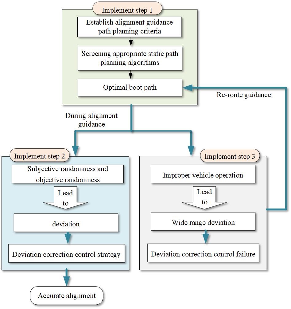
Fig. 1. Overall block diagram of alignment guidance and deviation correction control.
The specific implementation steps are as follows: first of all, determine the alignment guide path planning criteria, and conduct a global optimization of the guide path. Study the characteristic parameters associated with the vehicle’s warehousing path, and establish the constraint relationship between the relevant parameters and the path planning. Comprehensively, consider the size and orientation of the charging area, the surrounding environment of the garage, the distance of the guide path, the guide time, and the difficulty of the driver’s operation. Based on the static path planning method of the two-dimensional binary map scene, the appropriate static path planning algorithm is screened, and the guidance path evaluation system is determined. And quantitative indicators of key parameters. The shortest distance is used as the evaluation index, and the traditional Dijkstra algorithm and the improved Dijkstra algorithm are used as the path optimization method to obtain the optimal guidance path. Construct relevant constraints, study methods to avoid falling into local optima, and study evaluation methods of guiding paths.
Then, based on the optimal alignment guidance path, study the correction control strategy of EV when deviation occurs during parking as shown in Figure 2. In the process of real-time dynamic positioning and guidance of EVs, due to the subjective arbitrariness of human operation, certain deviations will inevitably occur, so it is necessary to propose corresponding control strategies to correct and control them. For this reason, based on real-time monitoring of deviations, in order to realize the dynamic correction control of EVs, an adaptive correction control strategy is proposed to complete the accurate alignment between the on-board end of the EV and the ground end. The specific pairing process is shown in the figure below for guidance and correction.
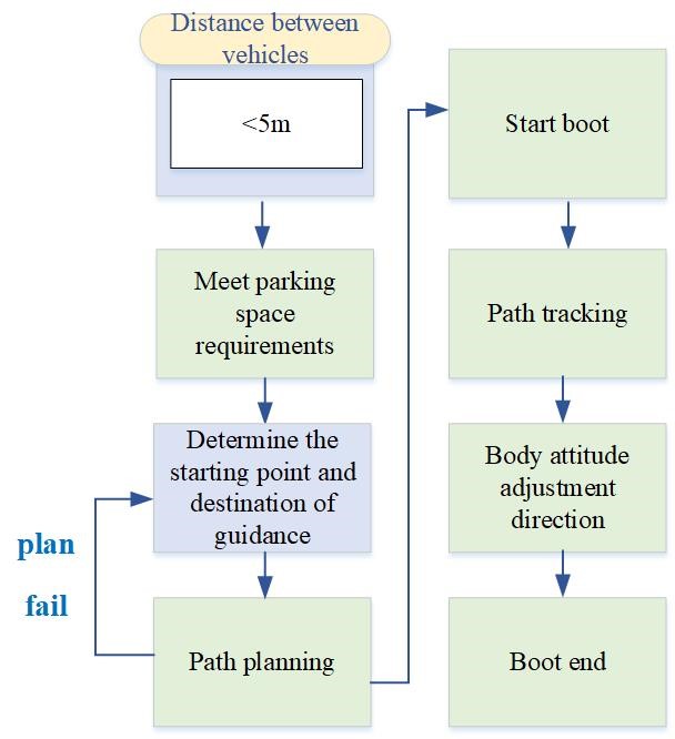
Fig. 2. Flow chart of alignment guidance and deviation correction control.
In the end, formulate the criteria for judging the deviation of the vehicle path, and study the method of re-planning the alignment guidance path. During the parking process, the vehicle may not enter the warehouse according to the alignment guide path, or due to improper operation, the vehicle deviates from the prescribed path in a large area, and the correction control fails. At this time, it is necessary to re-establish a new alignment guide path. Therefore, we must first study the criteria for judging that the path deviation is too large and the vehicle cannot return normally. Comprehensive consideration of the vehicle size, garage size, vehicle turning radius, and vehicle speed and other parameters, as well as the dynamic performance of the correction controller, establish the boundary conditions of whether the vehicle can follow the established path. Research on the comprehensive evaluation method of vehicle excursion under this boundary condition, and establish an accurate and fast judgment mechanism. Study the method of re-planning the alignment guide path when the vehicle deviates from a large-scale path. Based on the path and criteria, combined with the real-time posture of the vehicle, the guidance path is re-optimized and calculated, which improves the fault tolerance rate of vehicle alignment guidance and reduces the difficulty of warehousing.
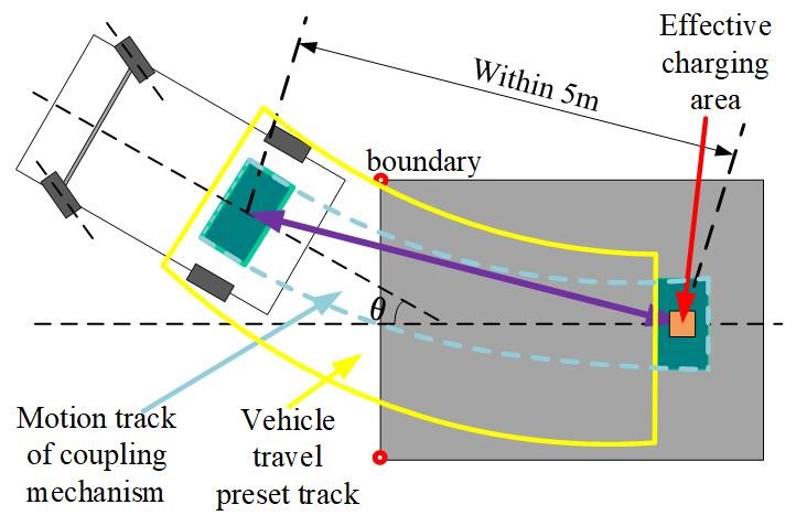
Fig. 3. Schematic diagram of parking guidance path.
III. FIELD CIRCUIT CO-SIMULATION OF HUMAN MODELS EXPOSED TO THE EMF OF EV WPT
A. Planar spiral WPT coil model and voxel human model and car shell model
In view of the actual situation of the impact of electromagnetic radiation on human safety when the EV WPT system is applied to the whole vehicle, the WPT coil, the ferrite core, and the whole vehicle are modeled and simulated in detail. The wireless charging coupling mechanism model in the ideal alignment state is shown in Figure 4.

Fig. 4. The physical modeling of wireless charging coil.
CST Microwave Studio for planar spiral WPT coil modeling. The number of turns at the transmitting coil of the WPT is 23, the minimum radius of the transmitting coil is 230 mm, and the spacing between two adjacent wires is 6 mm; the number of turns at the receiving coil is 8, the minimum radius at the receiving end is 130 mm, and the spacing between two adjacent wires is 6 mm. The minimum air gap is 140 mm, the maximum air gap is 170 mm, the standard air gap is 150 mm, and the maximum tolerance offset distance is 100 mm. A simple two-coil magnetic coupling will lead to the divergence and leakage of the magnetic line of force to the non-working area, and reduce the transmission efficiency of the system. Therefore, round cake ferrite cores are respectively arranged at 2 mm above the coil on the receiving side and 2 mm below the transmitting side. The relative permeability of the core is set to 1200, and the conductivity is set to 0.01 S m. In consideration of the cost and the weight of the WPT, the thickness of the ferrite core is 2 mm, and its radius is equal to the maximum radius of the coils on both sides.
Use the Hugo voxel model in the CST voxel family library as a human voxel anatomical model. In order to reduce simulation time and save computer resources, the accuracy of voxel dissection is set to 5 5 5 mm. The front view and dissection diagram of human voxel model are shown in Figure 5 (a) and Figure 5 (b), respectively.
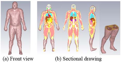
Fig. 5. Front view and sectional view of human voxel model for simulation.
EV can be regarded as a metal shell with good conductivity, which is mainly composed of floor, body and door, similar to a metal shielding shell with cavity. When modeling the car shell, it is divided into body, door, chassis, glass, tire, and seat. Considering the complexity of mesh generation and GPU resources, only the conductive material components such as body, door, and chassis are retained. The material property is set to iron, its conductivity is 1.04 10 S m, and the relative permeability is 4000. Figure 6 shows the interface after the 3D model of car shell is imported into CST. The size of car shell is 4.5 m 1.7 m 1.45 m. According to the requirements of GB/T38775.3-2020 electric vehicle wireless charging system Part 3 special requirements on the installation position of primary device, when using single module WPT charging device, the primary device of WPT coil is located between the middle and rear end of parking space.
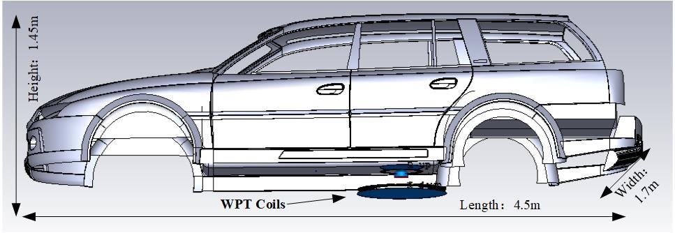
Fig. 6. Simulation model of car shell.
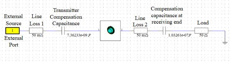
Fig. 7. Circuit topology diagram of wireless charging system.
B. Simulation study on electromagnetic exposure level of WPT coil to human body model in vehicle environment
Here, add the transient simulation task in CST design studio, and set the sine voltage with amplitude of 380 V and frequency of 85 kHz as the excitation of EMF simulation. The space EMF around the WPT coil is simulated by field circuit co-simulation method. According to the extracted parameters and the relationship between RLC resonant frequency and capacitance (1), the circuit topology simulation structure is established, as shown in Figure 7.
| (1) |
Take the basic full-wave formula of the electromagnetic safety numerical calculation of the human body model as the eqn (2).
| (2) |
where, H is the magnetic field intensity, B is the magnetic induction intensity, J is the current density, A is the vector magnetic potential, E is the electric field intensity, V is the potential, and D is the potential shift vector.
Import the human body voxel model Hugo into the car shell model, the vertical magnetic coupling resonance WPT system, lying and sitting positions, respectively. The body, resonator, and vehicle shell constitute a complete electromagnetic safety simulation system. The human body is set close to the resonator to simulate and calculate the electromagnetic radiation of the human body in different positions relative to the EV in different postures. They are standing close to the door (outside the car) near the resonator, lying on the front seat inside the car, and sitting on the front seat inside the car. The bio-electromagnetic safety of WPT system is evaluated in CST high-frequency simulation environment. The evaluation indexes are SAR, current density J, power density P of different organs, and magnetic induction intensity B of organs.
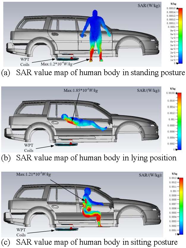
Fig. 8. SAR value distribution of EMF in WPT vehicle environment exposed to human body in three positions and different postures.
In the CST simulation, set the magnetic induction B probe, SAR probe, and current density J probe in the brain, heart, lung, liver, kidney, and foot of human voxel model, and the quantitative values of each organ under the electromagnetic radiation of WPT system in vehicle environment under three postures are calculated. According to ICNIRP, for electromagnetic waves from 3–400 kHz, the magnetic induction intensity B of public exposure should not exceed 27 T, the SAR limit is 0.02 W kg, the power density limit P is 10 W m, and the current density limit J is 2000 mA m.
From Figure 8, it can be concluded that the SAR index of electromagnetic exposure meets the limit requirements of 0.02 W kg, whether it is standing, lying and sitting, whether it is outside or in the vehicle. The results show that when lying in the car, the SAR value of lung is the largest, and the SAR value reaches 1.75 10 W kg, which is 8.75% of the standard. As can be seen from Figure 6, for current density J, the J of the heart position in the vehicle when lying in the car is the largest, which is 629 mA m, accounting for 31.45% of the standard limit; for magnetic induction intensity B, when standing at the door side, the maximum B at the foot reaches 45 T, which is 1.67 times of the standard limit.
The automobile chassis is a metal material. The magnetic field formed by eddy current generated by electromagnetic induction is just opposite to the working magnetic field of WPT system. Therefore, the chassis has a better shielding effect on the interior of the EV. However, the magnetic line of the counter magnetic field excited by eddy current effect will circle under the chassis and radiate to the side of the door, and then the EMF will be strengthened. This is the reason why the electromagnetic radiation in the area sandwiched between the chassis and the transmitting coil is bad.
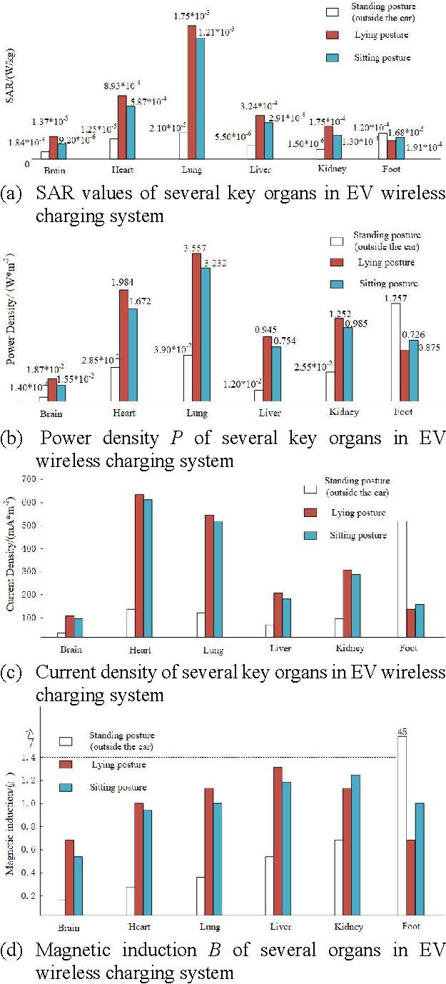
Fig. 9. SAR, P, J, B of six organs in EV wireless charging system.
From Figure 9, it can be drawn that the electromagnetic radiation of EV WPT system in the vehicle environment has a more serious impact on heart and lung organs than other organs, so they need to be focused on protection. Due to the electromagnetic shielding effect of car shell and the law that the electromagnetic dose decreases sharply with the increase of distance, the electromagnetic radiation index in the area above the safe height is basically better than that in the car. But the human foot is basically in the same horizontal plane with the WPT transmitting coil, and it is not protected by the electromagnetic shielding of the metal car shell, so when the human body is on the side of the car door, the electromagnetic radiation within the foot is very strong, the magnetic induction intensity of the foot is even as high as 45 T, which is beyond the safety limit, and the foot current density J is also large, about 500 mA m. It shows that the electromagnetic environment in the area between the plane of the chassis and the ground outside the coupling mechanism is relatively bad. Therefore, it is necessary to take corresponding electromagnetic shielding measures.
IV. BIO-ELECTROMAGNETIC SAFETY ASSESSMENT OF EV WPT
Through the theory of bio-electromagnetics, combined with the different weights of SAR, P, J, B damage to human organs, the comprehensive hazard index of electromagnetic radiation on human safety is proposed. As the main factor causing bio thermal effect, SAR index can represent the amount of electromagnetic energy absorbed by local organs of human body, which can best represent the impact of electromagnetic radiation on human body. The harm weight of SAR to human body is defined as 60%; power density P is the power value of the local tissue in the organ per unit cross-sectional area, and it also reflects the absorption of electromagnetic radiation by organisms. According to the requirements of GB/T 38775.4 (limits and test methods for electromagnetic environment of EV WPT) for exposure limits of active implantable medical devices, the magnetic induction intensity B ultrasonic standard will seriously interfere with the normal operation of human implantable medical devices, and the consequences are very serious. Therefore, B must be included in the comprehensive hazard index, and its weight is defined as 20%. According to the knowledge of bio-electromagnetics, it is pointed out in some progress of the research on specific absorptivity rate that the effect of selecting internal electric field strength E, induced current I (induced current density J) or SAR is the same, so the influence of current density J is not considered in the comprehensive hazard index , that is, the hazard weight of J to human body is defined as 0. In conclusion, the formula of comprehensive hazard index is as follows
| (3) |
where, SAR, P, and B are the limits of SAR, power density P, and magnetic induction B, obtained from ICNIRP and GB/T 38775.4-2020 respectively, and the limits are 0.02 W kg, 10 W m, and 27 T, respectively.
According to the formula, the comprehensive hazard index of each organ with three different postures in the vehicle’s different positions is summarized and calculated, as shown in Table 1. Case 1 represents human body in standing posture outside the EV. Case 2 represents human body lying in the EV. Case 3 represents human body sitting in the EV.
Generally speaking, the feet are most severely affected by electromagnetic radiation in the standing position, because the feet are close to the WPT coil or there is no metal shield in the standing position; the lung is the most seriously affected by electromagnetic radiation in lying posture, followed by the heart, which is significantly higher than other organs; in sitting posture, it is also the main cause of lung and heart. The comprehensive harm of electromagnetic radiation is greater, and the indexes of the two are slightly lower in the sitting position than in the lying position, because the organs are closer to the transmitting coil in the lying position. Therefore, the impact of the system on the heart and lung in the car is more serious than other organs, and it needs to be taken as the key protection object. The of other organs outside the car is significantly lower than that inside the car, except for the foot, which is the result of the shielding effect of metal car shell and the sharp attenuation of electromagnetic parameters with distance.
Table 1: Comprehensive hazard index of organs under three conditions
| Brain(%) | Heart(%) | Lung(%) | Liver(%) | Kidney(%) | Foot(%) | |
| Case 1 | 0.148483 | 0.316722 | 0.437296 | 0.484944 | 0.574019 | 37.207333 |
| Case 2 | 0.597019 | 7.387741 | 13.252889 | 3.824963 | 3.917889 | 2.057956 |
| Case 3 | 0.466007 | 5.845741 | 10.834741 | 3.269889 | 3.285926 | 3.063741 |
V. HUMAN EXPOSURE EMF TEST SYSTEM FOR EV WIRELESS CHARGING AND EMF MEASUREMENT
A. Non-emission non-metal carrier platform
Considering that the human body is directly exposed to the EMF of EV wireless charging system, the hand-held probe for EMF measurement has great risk, this chapter proposes the design of a joint test system for human body exposure to EMF of EV wireless charging, which is composed of a non-emission non-metallic carrying platform and a three-dimensional EMF test system for EV wireless charging. The EMF three-dimensional test system for EV wireless charging consists of EMF detection module, carbon fiber rod carrying module, servo lifting module, automatic positioning module, and EMF exposure limit evaluation module. The EV wireless charging pile used in the experiment was customized by a company in Xiamen. The experiment was carried out in the 10 m anechoic chamber of EMC laboratory in the experimental verification center of State Grid Electric Power Research Institute.
This non-emission bearing platform can carry the primary and secondary coils of the electric vehicle wireless charging pile, and can freely adjust the position parameters of the air gap distance, radial offset, and tilt angle in the six-axis direction, which can meet the requirements of the electric vehicle wireless charging pile Demand. Space electromotive force measurement under various working conditions of EV WPT. It is composed of non-metallic nylon 66, and the thermoplastic resin material avoids the interference of metal to electromagnetic radiation. Figure 10 is the design model and size drawing of the bearing platform.
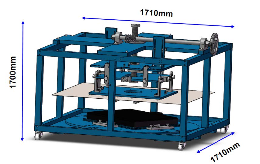
Fig. 10. Design model and dimension drawing of non-launch non-metal carrier.
The device needs to manually adjust the hand wheel and rotating components to adjust the relative position and angle between the transmitting plate and the receiving plate for EMF test. Control parameters include: X, Y, Z axis travel, translation distance, pitch (tilt) angle, and yaw (rotation) angle. The adjustable effective stroke of X, Y, and Z axes are 150 mm, 150 mm, and100 mm, respectively; the pitch angle (inclination angle) of receiving coil pad relative to transmitting coil pad is within ; the rotation around Z-axis is . Figure 11 is the main view of the non-emission platform and the functional description diagram of the components. In the receiving plate element, the upper part of the receiving coil-carrying plate is covered with steel plate, which is used to simulate the automobile chassis.
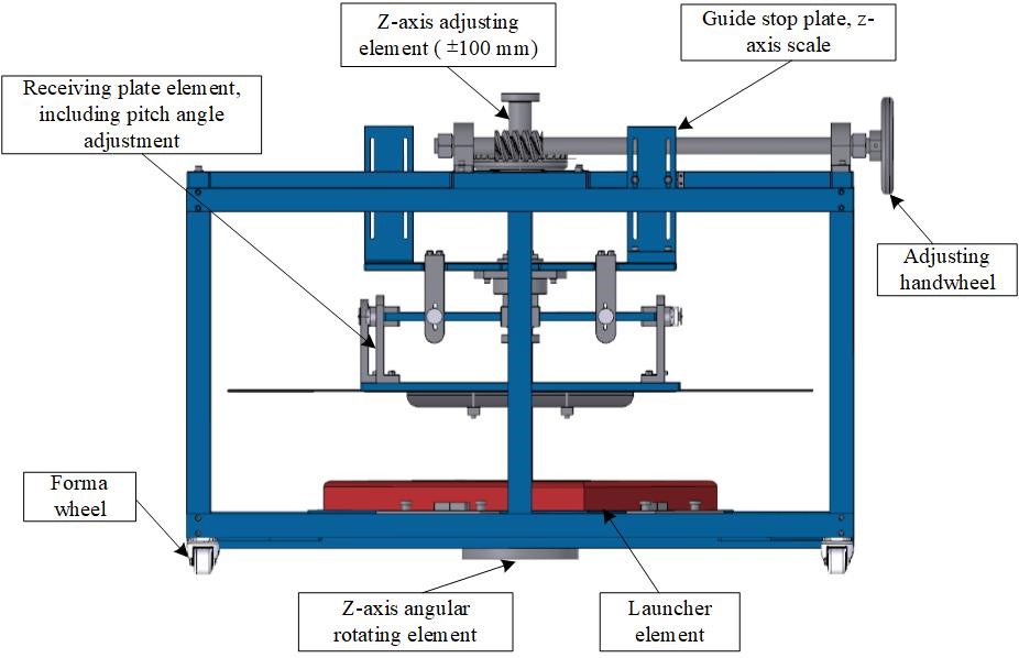
Fig. 11. Main view and component function description diagram of no launching carrier.
As shown in Figure 12, this is the physical drawing of the nylon-66 EV WPT non-emission carrying platform customized by the manufacturer according to the design model and dimension drawing.
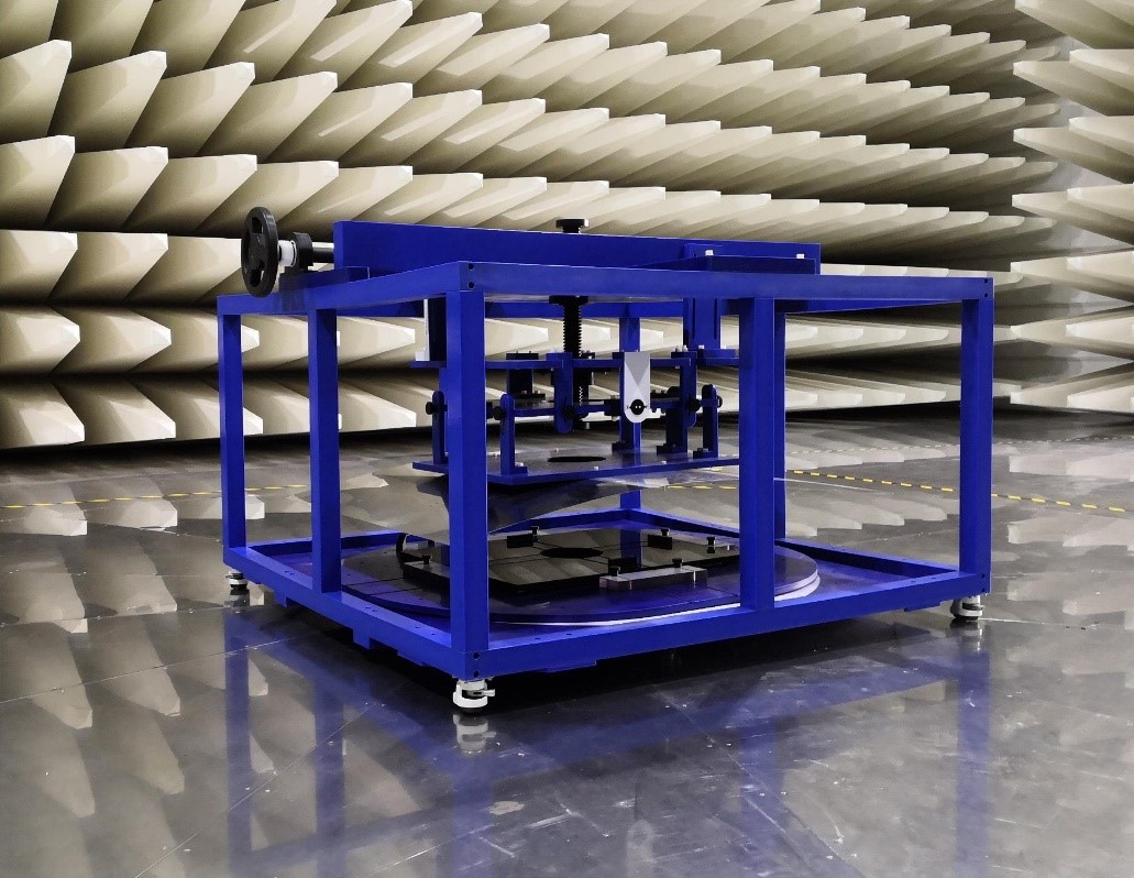
Fig. 12. Physical picture of non-emission non-metal carrying platform.

Fig. 13. Narda ELT-400 electromagnetic radiation analyzer.
B. EMF 3D test system for WPT of EV
As the above has completed the description of the components of the system. It has the function of automatically locating and measuring the EMF according to the protection area and test point specified in the standard. The EMF detection module is the probe for the actual measurement of EMF, and its main component is the German Narda ELT-400 electromagnetic radiation analyzer, as shown in Figure 13, with the frequency range of 1 Hz–400 kHz. Narda ELT-400 instrument is compact in design and equipped with three-dimensional omnidirectional electric and magnetic field sensors. The magnetic field strength can be measured up to 80 mT. Two sets of test standards, IEC 62233 and ICNIRP 1998, are stored in the instrument. In this paper, ICNIRP 1998 standard is selected for the experiment. The instrument displays the percentage of ICNIRP 1998 standard limit value, which can be converted into standard unit Tesla after processing.
The servo lift module and the carbon fiber rod carrying module form the probe positioning module. The servo lifting module can control the height of the probe and the forward distance of the probe relative to the original position. The carbon fiber rod carrying module can adjust the extended length of the carbon fiber rod, so as to control the X and Y coordinates of the probe. The automatic positioning module is controlled by the path-finding algorithm built in the host computer of the system. After the testers manually input the coordinates of the points to be tested according to the standard position, the test drive transmission system moves the probe to the points to be tested. The human exposure EMF limit evaluation module is a comprehensive processing module of three-dimensional human body model EMF simulation analysis and EV WPT electromagnetic environment evaluation method. The design diagram and physical diagram of EMF test system for EV WPT are shown in Figures 14 and 15, respectively.
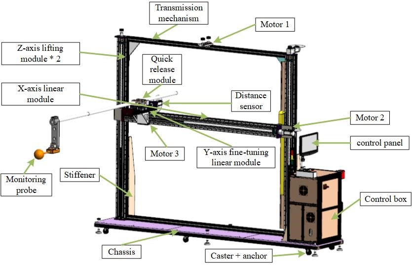
Fig. 14. Design of EMF test system for EV WPT.
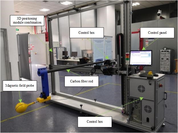
Fig. 15. Physical diagram of EMF test system for EV WPT.
WPT platform construction and surrounding EMF distribution test
According to the analysis of the circuit and hardware topology model of the magnetic coupling resonant WPT system, the primary rectifier inverter, power factor correction circuit, and WPT transmitter circuit are connected, and the secondary receiving circuit is well connected with rectifier and programmable load. The hardware diagram is shown in Figure 13. Since the electromagnetic radiation of programmable load will interfere with the test of WPT space EMF, the load is placed outside the darkroom, and the indoor WPT system is connected with the outdoor load through the connecting line. Therefore, the load is not reflected in Figure 16.

Fig. 16. Charging coil and loading platform.
As shown in Figure 17, the division direction of the eight corners of the WPT charging platform is based on the vertical direction of its four sides and four corners. On each angle, four lines are divided according to the vertical distance of 0 cm, 6 cm, 12 cm, and 18 cm from the WPT primary side coil (above). The WPT standard air gap is 15 cm. The specific test path is shown in Figure 17. Angles 1, 2, and 3 have been marked in the figure, and the angle increases clockwise. The magnetic induction intensity of 0–80 cm is measured from the four edge lines and four corners of the outer side of WPT transmitting coil along the straight line of eight angles. The EMF distribution curve measured in the space around the WPT coil with a standard air gap of 15 cm is given below. EMF distribution joint test system is given in Figure 18.
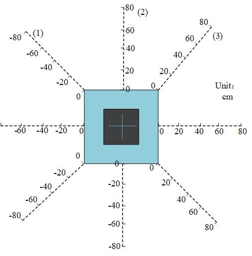
Fig. 17. EMF measurement angles and paths.
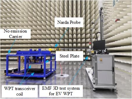
Fig. 18. EMF distribution joint test system.
It can be concluded from Figure 19 that when the 15 cm standard air gap is aligned, the magnetic field distribution of WPT at angles 1, 2, 3, 4, 5, and 8 is roughly the same, and the magnetic field distribution at different heights shows exponential attenuation with distance. Except for angle 2, when the distance between the primary coils is 0 cm or 6 cm, the magnetic field is the strongest, indicating that the magnetic field on the transmitting coil side is strong. When the radial safety distance from the outside of the transmitting coil is set to 20 cm, all angle can meet the limit value of 27 T. For angles 6 and 7, the EMF distribution is not quasi-exponential decay, and the magnetic induction of angle 6 is even as high as 120 T away from the transmitting coil 0 cm. The EMF value reaches limit requirements 27 T, when the radial distance is 40 cm from the outside of the transmitting coil. The radial safety distance which meets the magnetic field limit of angle 7, is also larger, which is 50 cm. The reason may be that the leading out direction of WPT primary and secondary sides power lead is close to angle 6, which makes the magnetic field distribution and amplitude of angle 6 and 7 change obviously compared with other angles.
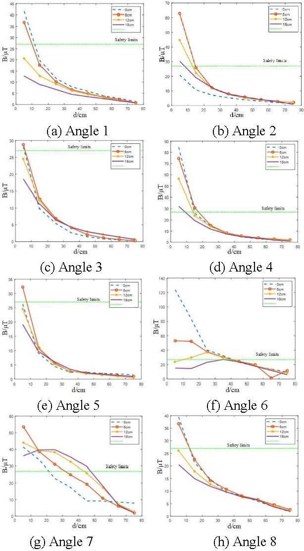
Fig. 19. EMF distribution around WPT with 15 cm air gap aligned.
Next, test the distribution of EMF around WPT when the radial offset is 10 cm (maximum offset).
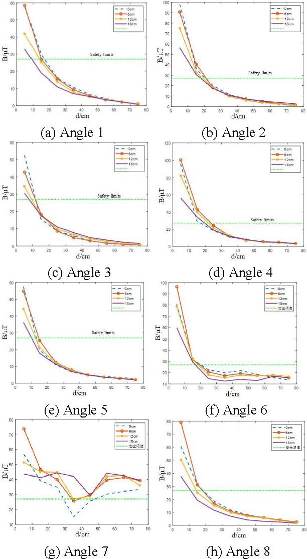
Fig. 20. EMF distribution around WPT with 10 cm radial offset.
It can be drawn from Figure 20 that the EMF distribution around the WPT coil with the maximum radial offset of 10 cm shows that the magnetic induction intensity is increased compared with the standard air gap of 15 cm aligned, which indicates that the offset will enhance the electromagnetic leakage of WPT. From the amplitude of EMF, the strongest magnetic field appears in the direction of angle 4, and the maximum value reaches 102.5 T when the vertical distance from the primary coil is 6 cm. The second largest magnetic field is 98.5 T when the vertical distance from the primary coil is 6 cm in the direction of angle 6. Except for angle 6 and 7, the other angles show exponential attenuation, and the maximum value still appears at 0 cm or 6 cm above the primary side coil of WPT, which verifies that the magnetic field near the primary side in the clamping area of WPT transceiver coil is strong, and the maximum EMF of angle 2 reaches 98 T when it is 0 cm away from the primary side coil. The maximum EMF of angle 8 is about 80 T when it is 6 cm away from the primary coil. The larger and irregular EMF values of angle 6 and 7 are related to the current leads between angle 6 and 7. The results show that the radial safety distance from the outside of the transmitting coil is set to 30 cm, which can basically meet the requirements of the EMF safety limit under the condition of full load maximum offset. Compared with the coil aligned, the safety distance under the condition of maximum offset is increased to 10 cm. In addition, the high magnetic field near the current leads on the primary and secondary sides should be treated separately, such as installing shielding sleeves on the leads to minimize the magnetic field.
VI. CONCLUSION
According to ICNIRP and SAE J2954 standards, based on the comprehensive hazard index of WPT electromagnetic radiation on human safety was proposed, the electromagnetic exposure level of WPT circular spiral coil to human body model in vehicle environment was studied. The simulation results show that the indexes of other organs exposed to WPT electromagnetic radiation except feet meet the standard limit requirements. In view of the problem that the EMF of the foot on the side of the door exceeds the standard, the electromagnetic shielding scheme should be adopted. This paper also designs a joint test system for spatial EMF distribution of WPT consisting of non-metallic non-emission platform and EV wireless charging EMF three-dimensional test system. The EMF distribution at different heights of 0–80 cm from the outside of the transmitting coil at eight angles around WPT is measured under the condition of 15 cm standard air gap aligned and the maximum radial deviation of 10 cm, so as to determine the safe working distance of WPT. It provides an effective interactive channel for the guidance of simulation prediction model to experiment and the verification of experiment to simulation prediction model.
ACKNOWLEDGMENT
The support of work from GYW51202001558 of Wuhan Branch of China Electric Power Research Institute, BE2019716 of Jiangsu social development project, 5500-202055070A-0-0-00 of Electric Power Research Institute of State Grid Jiangsu Electric Power Co., Ltd and 201911021 of Nanjing international cooperation project.
REFERENCES
[1] J. Pries, V. P. Galigekere, O. C. Onar, and G. J. Su, “A 50-kW three-phase wireless power transfer system using bipolar windings and series resonant networks for rotating magnetic fields,” IEEE Trans. on Power Electro., vol. 35, no. 5, pp. 4500-4517, May 2020.
[2] L. Wang, U. Madawala, and M. C. Wong, “A wireless vehicle-to-grid-to-home Power Interface with an adaptive DC link,” IEEE Jour. of Emerging and Selec. Topics in Power Electro., vol. 9, no. 2, pp. 2373-2383, Apr. 2021.
[3] A. S. Kaddour and S. Georgakopoulos, “Wireless power transfer using magneto-electric dipoles,” in 2019 International Appl. Comp. Electro. Society (ACES), Miami, FL, USA, pp. 1-2, Apr. 2019.
[4] Y. Liu, U. K. Madawala, R. Mai, and Z. He, “Zero-Phase-Angle controlled bidirectional wireless EV charging systems for large coil misalignments,” IEEE Trans. on Power Elrctro., vol. 35, no. 5, pp. 5343-5353, May 2020.
[5] L. Zhao, D. J. Thrimawithana, and U. K. Madawala, “Hubrid bidirectional wireless EV charging system tolerant to pad misalignment,” IEEE Trans. on Indus. Electro., vol. 64, no. 9, pp. 7079-7086, Mar. 2017.
[6] G. M. Noetscher, A. T. Htet, N. D. Maino, and P. A. Lacroix, “The visible human project male CAD based computational phantom and its use in bio-electromagnetic simulations,” 2017 Annual International Conference of the IEEE Engineering in Medicine and Biology Society (EMBC), Jeju, Korea, pp. 4227-4230, Sep. 2017.
[7] T. Campi, S. Cruciani, G. P. Santilli, and M. Feliziani, “Numerical analysis of EMF safety and thermal aspects in a pacemaker with a wireless power transfer system,” 2015 IEEE Wireless Power Transfer Conference, Boulder, USA, pp. 1-4, May 2015.
[8] A. Christ, M. Douglas, J. Nadakuduti, and N. Kuster, “Assessing human exposure to electromagnetic fields from wireless power transmission systems,” Proceedings of the IEEE, vol. 101, no. 6, pp. 1482-1493, Mar. 2013.
[9] J. H. Shim, K. J. Jung, and J. K. Byun, “Analysis of coupling factors for assessment of human exposure to magnetic field from wireless power transfer systems,” Journal of the Korean Institute of Illumina. and Electr. Installa. Engineers, vol. 32, no. 3, pp. 59-65, Mar. 2018.
[10] H. Schwan and C. Kay, “The conductivity of living tissues,” Annals of the New York Academy of Sciences, vol. 65, no. 06, pp. 1007-1013, Aug. 2010.
[11] A. Nazeri, A. Abdolali, and M. Mwhdi, “An extremely safe LOW-SAR antenna with study of its electromagnetic biological effects on human head,” Wireless Personal Communica., vol. 109, no. 3, pp. 1-14, Nov. 2019.
[12] L. Gun and X. F. Pang, “Biological effects of environmental electromagnetic fields,” Advanced Materials Research, vol. 183, no. 185, pp. 532-536, Jan. 2011.
[13] L. Hardell and C. Sage, “Biological effects from electromagnetic field exposure and public exposure standards,” Biomedi. & Pharmaco., vol. 62, no. 2, pp. 104-109, Feb. 2008.
[14] S. T. Khang, S. C. Chae, T. D. Yeo, and J. W. Yu, “Open-loop maximum efficiency tracking wireless power transfer for biomedical implants,” 2016 European Microwave Conference, London, UK, pp. 1147-1150, Oct. 2016.
[15] Q. Rui, D. Wu, C. Ji, S. Wang, D. Wilton, and W. Kainz, “An efficient two-dimensional FDTD method for bio-electromagnetic applications,” IEEE Trans. on Magnetics, vol. 42, no. 4, pp. 1391-1394, May 2006.
[16] I. Meny, N. Burais, F. Buret, and L. Nicolas, “Finite-element modeling of cell exposed to harmonic and transient electric fields,” IEEE Trans. on Magnetics, vol. 43, no. 4, pp. 1773-1776, Apr. 2007.
[17] N. Shinohara, “Trends in wireless power transfer: WPT technology for energy harvesting, mllimeter-wave/THz rectennas, MIMO-WPT, and advances in near-field WPT applications,” IEEE Microwave Magazine, vol. 22, no. 1, pp. 46-59, Jan. 2021.
BIOGRAPHIES

Hongyan Sun is an Assoc. Professor with Nanjing Normal University, Taizhou College. She is a graduate student from Nanyang, Henan Province, graduated in Control Theory and Control Engineering from Zhongyuan University of Technology. Her main research interests are Intelligent Control and Electromagnetic Compatibility.

Shiliang Hou was born in Shandong Province, China. He received his master’s degree from School of Electrical and Automation Engineering from Nanjing Normal University, Nanjing, China, in 2021. He is currently working in State Grid Shandong Maintenance Company, Jinan, China. His major research interest is new technology of electrical engineering.

Yang Zhao received his B.E., M.E., and Ph.D. degrees in Power Electronic Technology from Nanjing University of Aeronautics and Astronautics, Nanjing, China, in 1989 and 1992, and 1995, respectively. He is currently the professor with Nanjing Normal University. His research interests are in the areas of Electromagnetic Compatibility, Power Electronics, and Automotive Electronics.

Wei Yan is a Doctor and Assoc. Professor with Nanjing Normal University. He received his M.S. degree in Electrical Engineering and obtained Ph.D. in Physics and Electronics from Nanjing Normal University in 2011 and 2014, respectively. He is the Senior Member of China Electrical Technology Association and the evaluation expert of the Electromagnetic Compatibility Calibration Specification of China.

Yongji Wu was born in Shanxi Province, China. He received his bachelor’s degree from Shanxi Institute of Engineering and Technology in 2018. He is currently studying for a master’s degree in Electrical Engineering at Nanjing Normal University. The main research direction is new technology of power system.
ACES JOURNAL, Vol. 36, No. 10, 1355–1366.
doi: 10.13052/2021.ACES.J.361012
© 2021 River Publishers