Design and Analysis of Multi-Mode Distributed Array with Hybrid Optimization Method
Shutao Fang, Weiming Li, Wu Ren, and Zhenghui Xue
School of Information and Electronics
Beijing Institute of Technology, Beijing, 100081, China
bit_fst@163.com, wmli@bit.edu.cn, renwu@bit.edu.cn, zhxue@bit.edu.cn
Submitted On: October 9, 2021; Accepted On: November 17, 2021
Abstract
In this paper, we presented an improved hybrid optimization method to construct distributed array with two identical sub-arrays, which is mainly applied on airplanes as the front-end of communication and detection system. According to different demands on array’s gain and operating distances, the proposed method presents a scheme of implementation of two operate modes by optimizing elements’ positions and excitations. Two sub-arrays are able to work together to realize high gain when the object is quite far away, and one sub-array is able to work alone when the object is relatively close. This method is presented based on Particle Swarm Optimization (PSO) method and convex method, accomplishing that peak sidelobe level (PSLL) of whole array is lowered under -10 dB, and PSLLs of sub-arrays are lowered under -20 dB by supplementing some auxiliary units and re-optimizing array’s excitation distribution. In the procedure of optimization, the hybrid method is designed catering to multiple constraints according to the requirements of practical application. A specific example for synthesizing reconfigurable distributed array is provided and the sensitivity of obtained performance affected by interference of optimized results is discussed.
Index Terms: convex optimization, differential evolution algorithm, distributed array synthesis, grating lobe suppression, PSO Optimization Algorithm.
I. INTRODUCTION
With the requirements of radar and communication systems applied on complex platform, distributed array is attracting more and more attention and research nowadays[1, 2]. Different from traditional array, distributed array has better flexibility of array configuration and enlarges array’s aperture on account of the cooperation of sub-arrays. With large array aperture, distributed array has higher directivity and narrower main lobe width, realizing desirable features like good spatial resolution and angular accuracy[3]. As for distributed array with a few sub-arrays, it has broad application prospects because of its good flexibility on array arrangement. For example, when applied on airplane as the front-end of radar system, distributed array is able to be arranged on a side of the fuselage, taking full advantage of the available space to make the aperture as large as possible. In [4], we have proposed a hybrid method to optimize distributed array, the optimized PSLL is –10 dB.
Considering that optimized distributed array’s PSLL is still higher than traditional antenna array, it will be helpful to enhance array’s applicability if it can operate in different modes in which array’s PSLL can be suppressed lower. For example, when the target is relatively close to the plane, the detecting result obtained from a single sub-array might be better since the sub-array has the potential of reaching lower PSLL, ensuring sub-arrays’ ability of isolated operation would be a good way of improvement. However, performance of sub-arrays with elements’ locations and excitation distribution presented in [4] is not good enough to put into practical application. Therefore, the optimized distributed array should be further improved to cater to the demand.
Nowadays, a lot of optimization researches have been done to improve the performance of large-spaced antenna array. Many global optimization algorithms are used on array synthesis, such as Genetic Algorithm (GA), Simulated Annealing (SA), Particle Swarm Optimization (PSO) and Differential Evolution (DE) [5, 6, 7, 8, 9, 10, 11, 12, 13, 14, 15]. Considering that array optimization problem has high degree of freedom, global optimization methods will be helpful to improve array’s performance. Furthermore, distributed array synthesis is a high-dimensional nonlinear problem, convex optimization method has been considered and widely researched for array synthesis. As proposed in [16, 17, 18, 19], convex optimization is usually applied to improve the sparsity of array. According to its optimization principle of using -norm, convex optimization is also able to be leverage to solve the problem of distributed array synthesis.
In this paper, based on the result in [4], we propose a hybrid optimization method specially for designing and constructing distributed array with multiple operating modes. Considering that the array to be modified is sparse, and only change the locations and excitations of original elements will badly affect the whole array’s pattern, it is possible to improve sub-arrays’ performance by interpolating elements and adjusting their parameters. To accomplish the model switch of array, binary codes are adopted to control the on-off state of array elements to make the whole array reconfigurable and normally operate in different mode. Meanwhile, in order to guarantee both whole array and sub-arrays perform well, the distributed array should be holistically optimized after sub-array construction. With this method, the performance of sub-arrays are significantly improved and the pattern of the whole array is almost unaffected. Since elements’ positions and excitations are optimized and fixed, it is also convenient to switch operation mode by just changing the on-off state of array elements.
The paper is organized as follows: In Section II, configuration and performance of array to be improved are introduced and the hybrid method to design reconfigurable distributed array are proposed. Optimized numerical results are presented in Section III. Array’s tolerance to excitation error and element position error are statistically analyzed in Section IV. Conclusions are given in Section V.
II. ARRAY’S CONFIGURATION AND HYBRID METHOD TO DESIGN MULTI-MODE DISTRIBUTED ARRAY
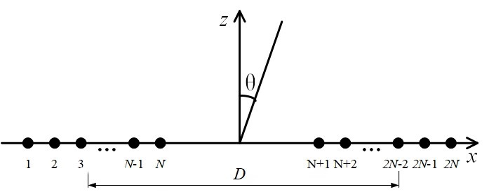
Figure 1: Model of distributed array with two identical sub-arrays.
Uniform distributed array is formed by two identical sub-arrays arranged in line, as shown in Figure 1. Each sub-array has N isotropic elements, and the distance between two adjacent units equals to half wavelength. The far-field pattern of distributed array can be calculated by
| (1) |
where represents sub-arrays’ pattern and is the distance between two sub-arrays. The whole distributed array can be regarded as a large binary array. The radiation performance of the distributed array factor is coherent with the typical pattern of a binary array. If all elements in every sub-array are evenly spaced arranged and uniformly excited, patterns of whole array and sub-array are shown in Figure 2. PSLL of distributed array is -2.47 dB.
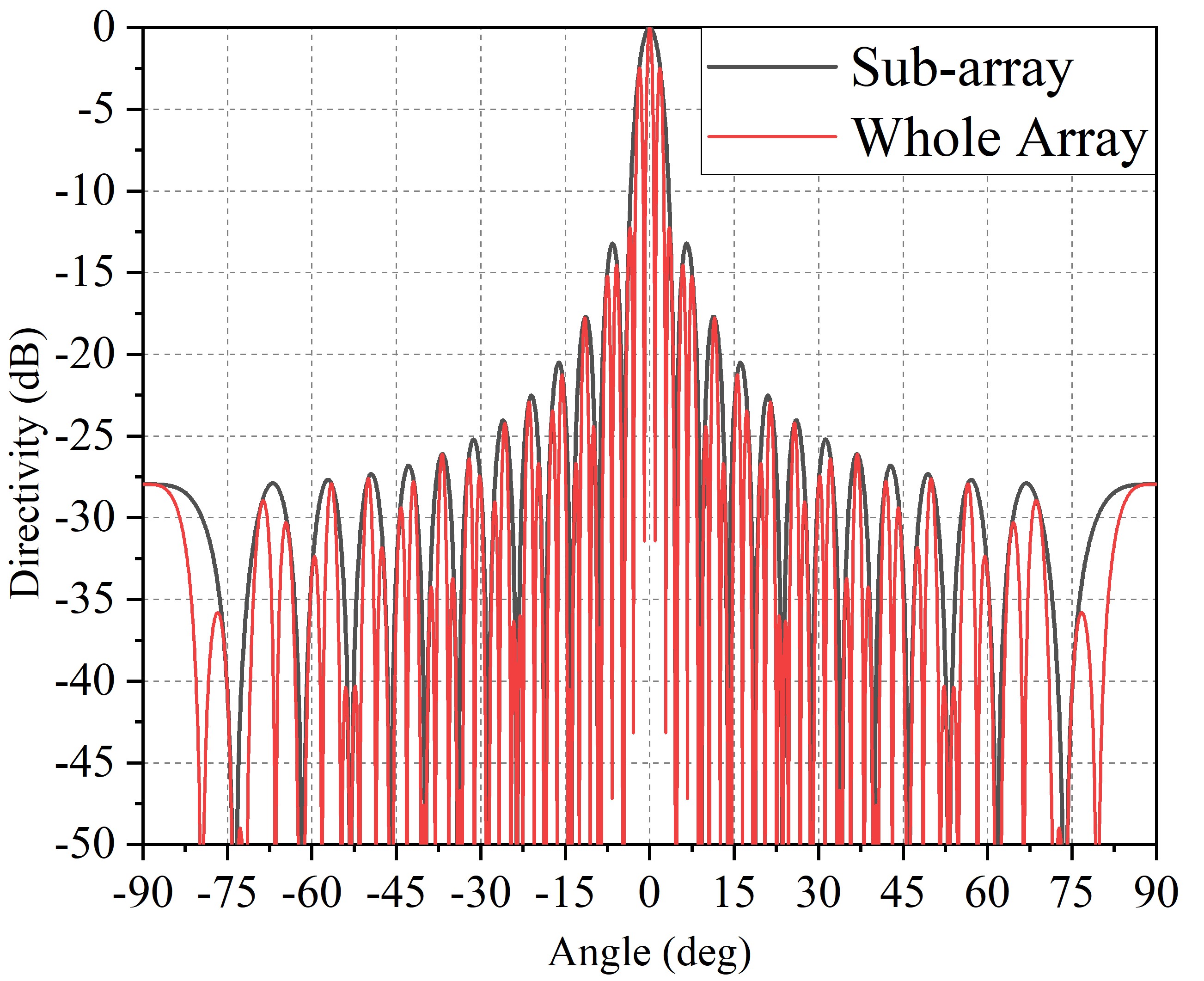
Figure 2: Normalized Patterns of distributed array and sub-array. All elements are evenly spaced arranged and uniformly excited.
In [4], we proposed a new hybrid method to optimize the global performance of distributed array, in which every sub-array has 25 elements. PSLL of the whole array is lower than -10 dB, exactly equal to -10.6624 dB, far lower than original PSLL of -2.1594 dB. However, both sub-arrays are badly deteriorated, where the PSLL of left and right sub-arrays are respectively equal to -6.5776 dB and -2.5718 dB. The patterns of two sub-arrays resulted from global optimization are shown in Figure 3.
In order to accomplish the reconfiguration of distributed array, sub-arrays’ performance should be improved first. Based on the sparsity of sub-arrays, we present a hybrid method to improve the performance of sub-array method by adding supplementary units into sub-arrays and presenting binary code to control the on-off state of array’s elements.
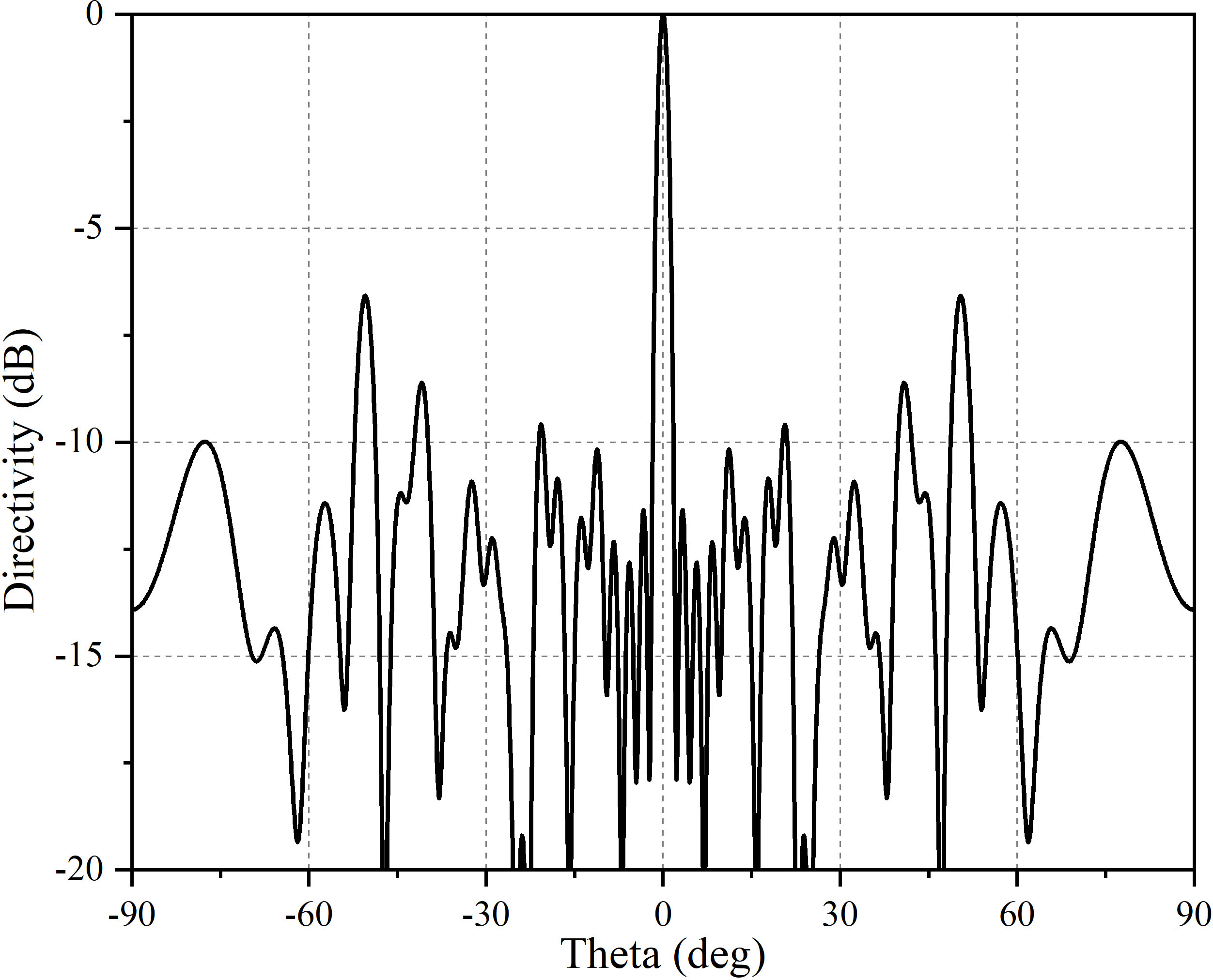
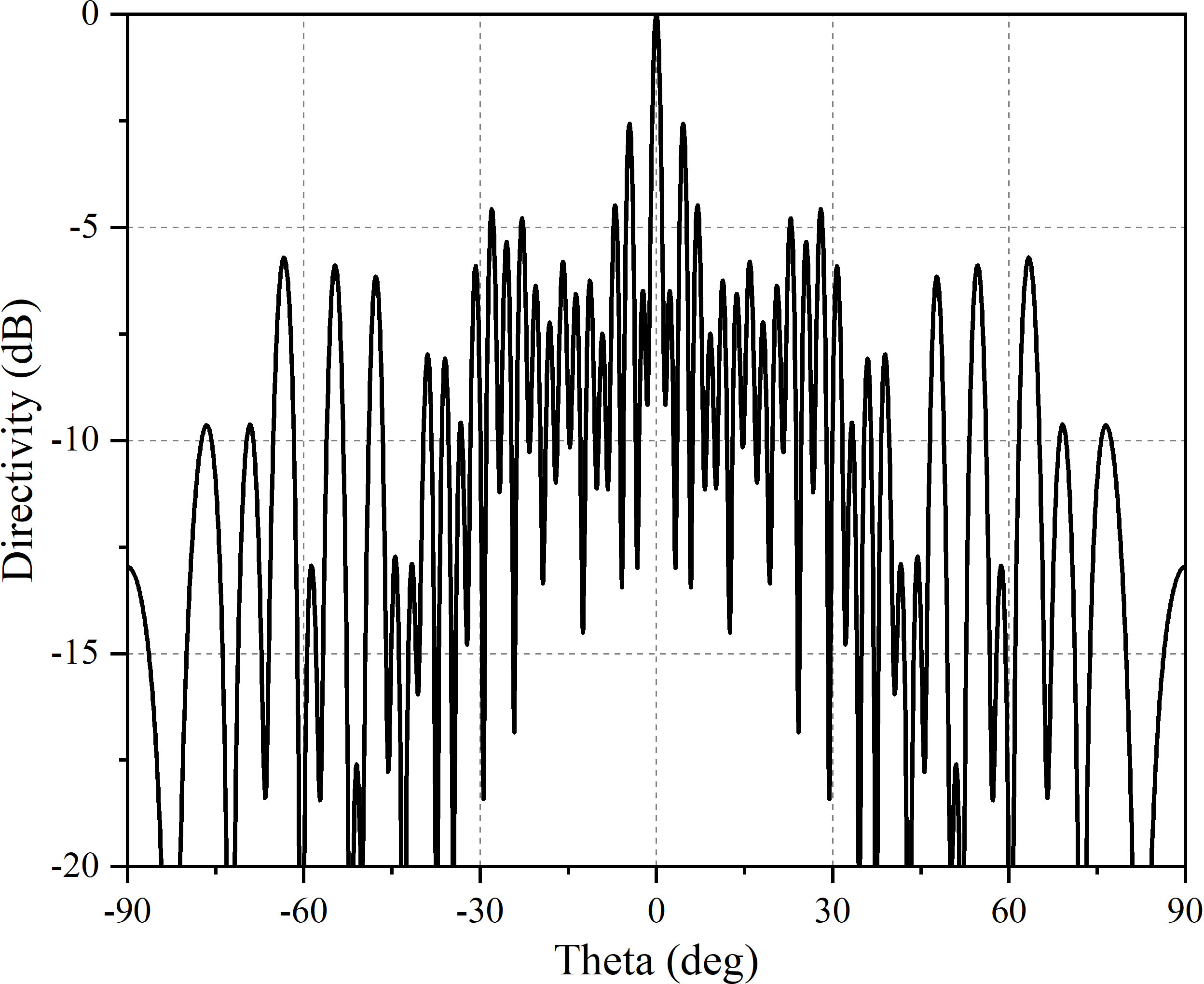
Figure 3: Normalized directivity pattern of left and right sub-arrays. Elements’ positions and excitations are respectively as Table 1 and Table 2 shows.
A. Reconfigurable sub-array design
For the optimized distributed array, inter-element distances of sub-arrays are enlarged, the sparsity of which gives enough space to interpolate more elements. After presetting minimum inter-element spacing, supplementary elements should be added as much as possible to ensure enough degrees of freedom of sub-array optimization. According to test, not all elements are required to get involved in sub-arrays. Therefore, sub-arrays with added elements should be thinned in the next step to find optimal sparse scheme.
During the process, global optimization algorithms will be helpful to interpolate elements. In this paper, PSO is adopted with advantages of simpleness and quickness. To accomplish optimization of sub-arrays, we take PSLL as an indicator to search the optimal result. Therefore, PSLL and the fitness function are
| (2) |
| (3) |
The iterative formula of PSO is shown as
| (4) |
where and are velocity vector position vector of th element, is the best individual in one iteration and is the best individual during the whole process of optimization, and k is the inertia weight to control the search capability of algorithm.
During the process, we set that the interval between two adjacent elements is no less than . The fitness function and constraints are described as
| (5) |
After this procedure, optimal result of element interpolation is obtained. All added elements are temporarily uniform excited in the result. In the next step, both original elements and added elements are getting involved in the selection to form new sub-arrays. In this process, binary PSO (BPSO) is used to determine the selection of sub-arrays’ elements, which is presented by Kennedy in 1997 [20] and used for antenna and array design to get better radiation performance[21, 22, 23, 24].
Here a logistic transformation sigmoid() is used to constrain to the integer 1 or 0, and the relationship between the value of and sigmoid() is shown as follow.
| (6) |
| (7) |
During the interpolation and selection of elements, two weight vectors should be recorded. One is the thinning weight vector describing sub-arrays’ sparsity, named as . The other is to mark interpolated elements, named as . Two vectors are defined as follows.
| (8) |
| (9) |
Assuming that the sum of elements making up new sub-array is , the pattern of new sub-array will be calculated by
| (10) |
B. Excitation Optimization
In order to get optimal performance of sub-arrays, elements’ excitations should be optimized as well. Assuming is the directivity of sub-array before optimized, the constraints can be expressed as
| (11) |
where is the preset parameter to help finding the lowest PSLL. Assuming sub-arrays’ excitation vector is . To identify elements whose excitations should be optimized, weight vector are obtained by
| (12) |
By vectorizing eqn (10) and adding the weight vector , constraints in eqn (11) can be rewritten as
| (13) |
The optimization problem is described as
| (14) |
Here minimization optimization is considered to optimize the excitations of array. To get a better solution, a range of favorable weighting matrices for a fixed when is unknown and iterative computation procedure that alternates between obtained and redefining new weights are adopted. The optimization problem in th iteration is
| (15) |
| (16) |
It should be noticed that excitation optimization is supposed to proceed simultaneously with element selection to find the optimal result. After this process, excitations of original elements getting involved in restructuring sub-arrays are changed, resulting in bad influence to the performance of the whole array. Therefore, original elements not involved in new sub-arrays will be helpful to reduce the deterioration by tweaking their excitations. Here, convex optimization method is also suitable for the operation. Assume that is the weight vector to mark elements to be adjusted, in which 1 represents elements whose excitations will be tweaked and 0 represents elements which remain unchanged. The adjustment problem is described as
| (17) |
The iteration during the process is the same as eqn (16).
After all procedures proposed above, the design of distributed array with multiple operation modes is finished. Binary codes controlling elements’ on-off state are also obtained. The design process is summarized as follows:
1. Add supplemental elements into sub-arrays as much as possible and adjust their locations.
2. Select proper elements to reassemble new sub-arrays.
3. Solve convex problem (15) to get optimal result under arrangement designed in step 2.
4. If the optimal result meet the demand, end the iteration.
5. If not, repeat steps 1 to 3 until the desirable PSLL is obtained or the number of iterations is reached.
6. Get weight vectors to control the working state of elements.
7. Solve convex problem (17) to optimize performance of the whole array.
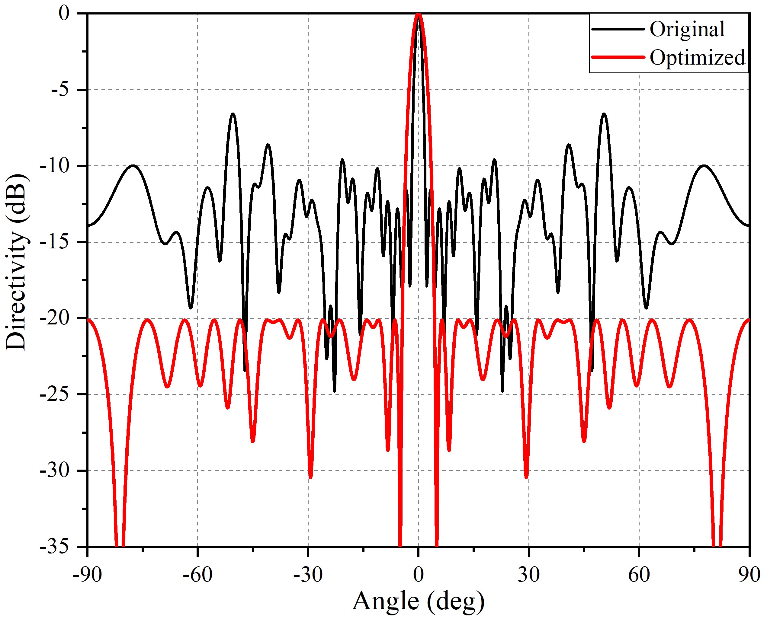
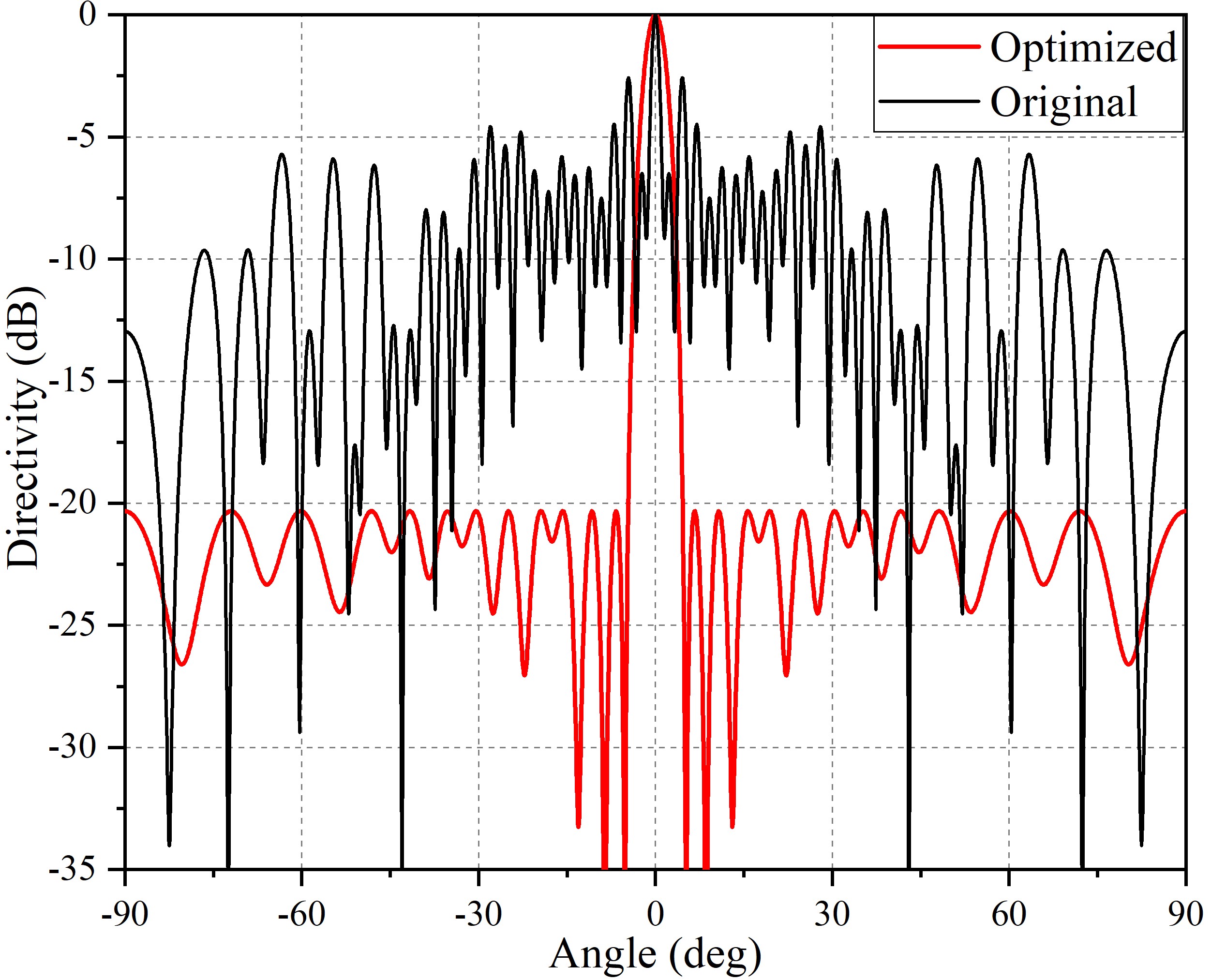
Figure 4: Comparison of normalized original pattern and optimized pattern of two sub-arrays. First figure is pattern of left sub-array and the other is pattern of right sub-array.
III. NUMERICAL RESULTS
Here, results of designing the multi-mode distributed array are presented to assess the capability and effectiveness of the hybrid method. Distance between two sub-arrays is . The number of elements in the whole array is 50 and both original sub-arrays contain 25 elements.
To keep the scale of reconstructed sub-arrays as the same as the original, the number of elements getting involved in new sub-arrays are artificially preset as 25. During the process, the desired PSLLs of sub-arrays are set as -20 dB and the PSLL of the whole array after sub-array design is hoped to be maintained under -10 dB. In the procedure of element interpolation, the minimum inter-element distance is preset as . According to practical calculation tests, 100 times of PSO iterations and 20 times of convex optimization iterations are enough to get optimal result.
Figure 4 shows the comparisons of original sub-arrays and the optimized reconstructed sub-arrays. Optimization results of elements’ positions and excitations of reconstructed two sub-arrays are presented in Table 1 and Table 2, in which the supplementary elements are marked “1” and original elements are marked “0”. The unit of element positionis .
Table 1: Optimized positions and excitations of left sub-array
| No. | Posit. | Excit. | If added |
|---|---|---|---|
| 1 | 8.50 | 0.0758 | 0 |
| 2 | 9.69 | 0.4898 | 0 |
| 3 | 10.84 | 0.7541 | 0 |
| 4 | 11.24 | 0.2145 | 1 |
| 5 | 11.64 | 1.0805 | 1 |
| 6 | 12.05 | 0.1824 | 0 |
| 7 | 12.47 | 0.8190 | 1 |
| 8 | 12.91 | 0.3002 | 1 |
| 9 | 13.50 | 0.8716 | 0 |
| 10 | 13.99 | 0.2831 | 1 |
| 11 | 14.40 | 0.9619 | 1 |
| 12 | 15.37 | 1.0704 | 1 |
| 13 | 16.21 | 0.9172 | 0 |
| 14 | 17.20 | 1.1829 | 0 |
| 15 | 17.70 | 0.8281 | 1 |
| 16 | 18.12 | 0.9002 | 0 |
| 17 | 18.63 | 0.3515 | 1 |
| 18 | 19.10 | 0.7759 | 1 |
| 19 | 19.57 | 0.0726 | 0 |
| 20 | 20.16 | 0.7240 | 0 |
| 21 | 20.76 | 0.6283 | 1 |
| 22 | 21.23 | 0.4384 | 0 |
| 23 | 21.89 | 0.4468 | 0 |
| 24 | 22.41 | 0.2567 | 0 |
| 25 | 22.95 | 0.6680 | 0 |
For the left sub-array, PSLL of original pattern is -6.5776 dB, while the PSLL of optimized pattern is -20.1245 dB. For the right sub-array, PSLL of original pattern is -2.5718 dB, and PSLL of optimized pattern is -20.3247 dB. Compared with original sub-arrays, performance of reconstructed sub-arrays has significantly improved.
Affected pattern and optimized pattern of whole array are shown in Figure 5. The PSLL of affected pattern is equals to -6.91 dB. By optimizing excitations of other elements, PSLL of the whole array is lowered to -10.12 dB. Optimized results are listed in Table 3. Compared with original distributed array, whose PSLL is -10.6624 dB, result obtained from design method proposed in this paper is slightly higher, which is acceptable.
To research if optimized pattern would be affected when main beam points at different angles, we calculated distributed array’s pattern when directions of main beam are 15 deg, 30 deg and 60 deg. Results are shown in Figure 6. It clearly shows that when array’s elements are isotropic, main beam deflection is of no influence on PSLL of optimized distributed array.
Table 2: Optimized positions and excitations of right sub-array
| No. | Posit. | Excit. | If added |
|---|---|---|---|
| 1 | 43.30 | 0.4787 | 0 |
| 2 | 43.81 | 0.4661 | 0 |
| 3 | 44.44 | 0.3169 | 0 |
| 4 | 44.99 | 0.5370 | 0 |
| 5 | 45.60 | 0.6914 | 0 |
| 6 | 46.42 | 0.9867 | 0 |
| 7 | 47.59 | 0.8062 | 0 |
| 8 | 48.06 | 0.5422 | 1 |
| 9 | 48.51 | 0.9421 | 1 |
| 10 | 48.98 | 0.1754 | 0 |
| 11 | 49.39 | 0.9837 | 1 |
| 12 | 49.80 | 0.0306 | 1 |
| 13 | 50.20 | 1.0501 | 0 |
| 14 | 50.71 | 0.1044 | 1 |
| 15 | 51.17 | 0.8562 | 1 |
| 16 | 51.59 | 0.4388 | 0 |
| 17 | 52.19 | 1.1783 | 1 |
| 18 | 52.61 | 0.3757 | 1 |
| 19 | 53.02 | 1.1090 | 0 |
| 20 | 53.45 | 0.3466 | 1 |
| 21 | 53.85 | 0.9394 | 1 |
| 22 | 54.25 | 0.1085 | 0 |
| 23 | 54.78 | 0.7255 | 1 |
| 24 | 55.20 | 0.0366 | 1 |
| 25 | 55.61 | 0.5992 | 0 |
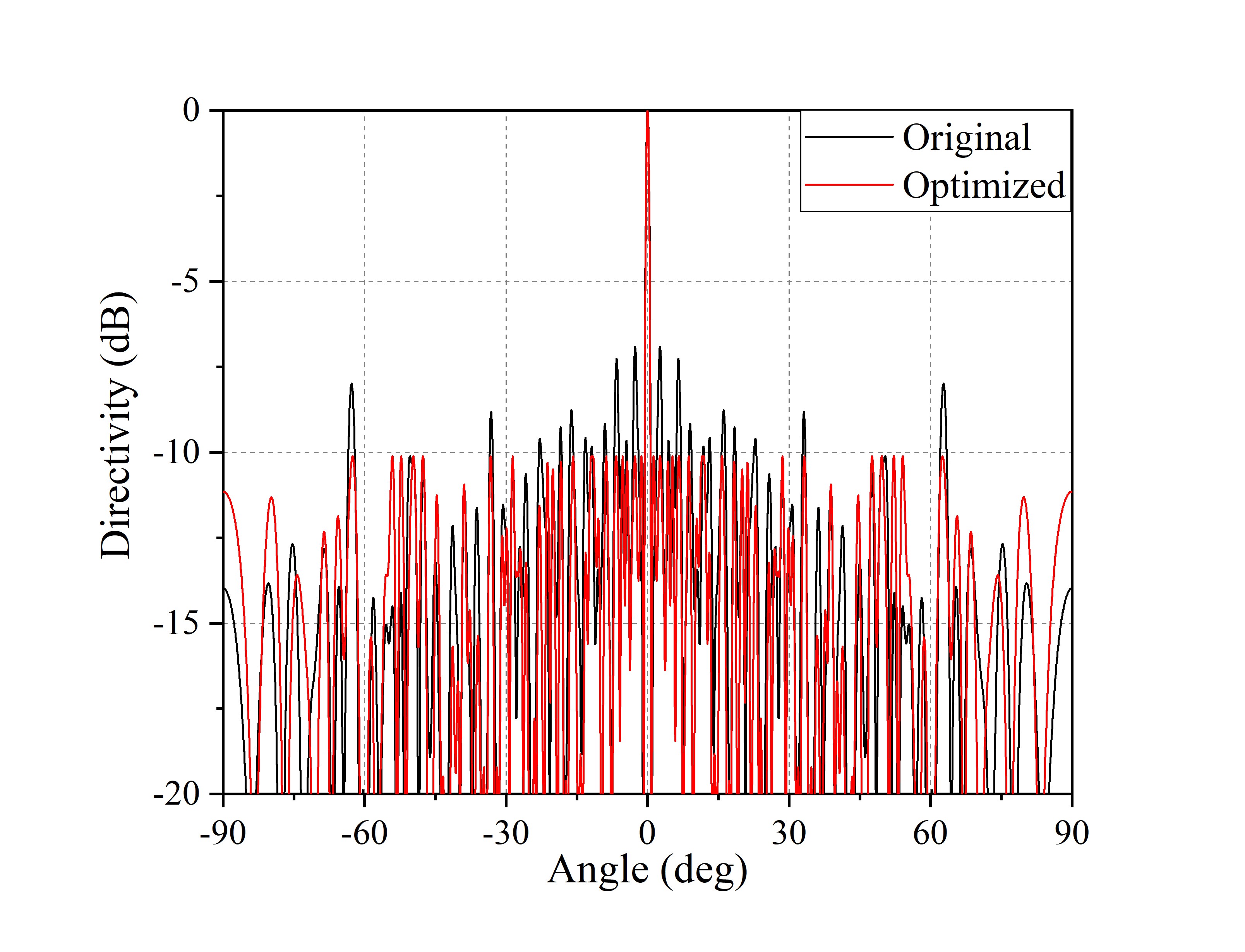
Figure 5: Comparison of normalized pattern of distributed array. The black line shows the deteriorated pattern of distributed array without second optimization, and the red line shows optimized pattern.
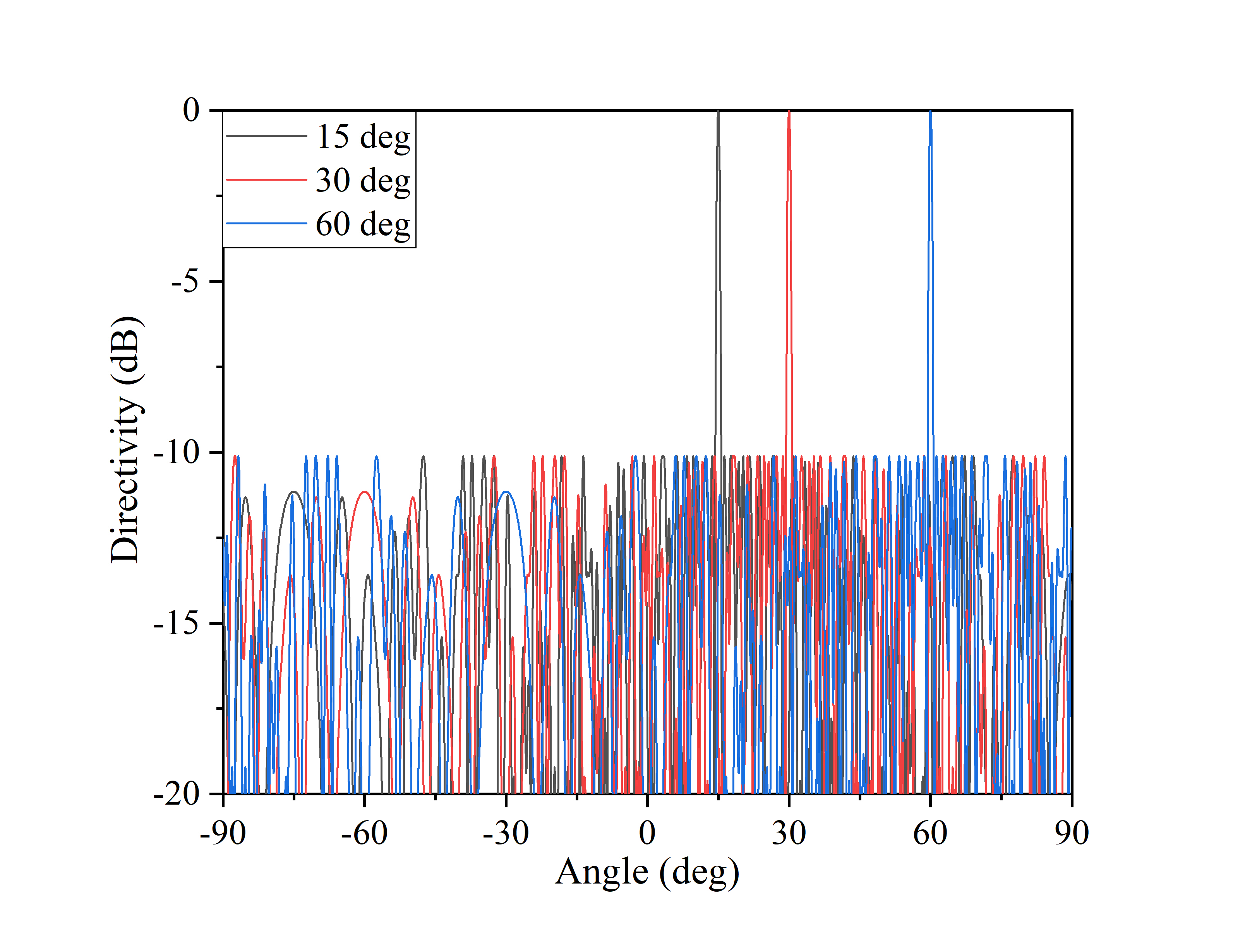
Figure 6: Normalized pattern of distributed array when its main beam points at 15 deg, 30 deg, and 60 deg respectively.
The entire process of optimization is based onMATLAB 2018b on Windows 10, with hardware configuration of Intel Core i7-8700 CPU 3.20GHz and 48.0GB RAM. The convex optimization problems discussed above can be solved by professional MATLAB toolbox efficiently, such as CVX Toolbox.
With sufficient sampling point on array’s pattern, computation time of a single circulation from step 1 to step 3 is around 55 seconds. Meanwhile, the process in step 7 with 20 iterations needs around 17 seconds.
IV. INFLUENCE OF POSITION AND EXCITATION ERRORS
Considering that all results obtained from the method proposed before are too accurate, when designed distributed array works in different modes, performances of both sub-arrays and whole array will be sensitively affected by errors in elements’ positions and excitations, which should be estimated to further analyze the stability of distributed array. Therefore, we will give error analysis on array performance in this section.
Table 3: Optimized positions and excitations of right sub-array
| No. | Posit. | Excit. | No. | Posit. | Excit. |
|---|---|---|---|---|---|
| 1 | 0 | 0.2673 | 26 | 42.01 | 4.1974 |
| 2 | 1.00 | 1.3577 | 27 | 42.60 | 1.9057 |
| 3 | 1.81 | 0.7584 | 28 | 43.30 | 0.4787 |
| 4 | 2.82 | 0.2774 | 29 | 43.81 | 0.4661 |
| 5 | 3.62 | 0.8353 | 30 | 44.44 | 0.3169 |
| 6 | 4.35 | 0.4523 | 31 | 44.99 | 0.5370 |
| 7 | 5.58 | 0.6042 | 32 | 45.60 | 0.6914 |
| 8 | 7.07 | 0.6341 | 33 | 46.42 | 0.9867 |
| 9 | 8.50 | 0.0758 | 34 | 47.59 | 0.8062 |
| 10 | 9.69 | 0.4898 | 35 | 48.97 | 0.1754 |
| 11 | 10.84 | 0.7541 | 36 | 50.20 | 1.0501 |
| 12 | 12.05 | 0.1824 | 37 | 51.59 | 0.4388 |
| 13 | 13.50 | 0.8716 | 38 | 53.02 | 1.1090 |
| 14 | 14.91 | 1.7641 | 39 | 54.25 | 0.1085 |
| 15 | 16.21 | 0.9172 | 40 | 55.60 | 0.5992 |
| 16 | 17.20 | 1.1829 | 41 | 56.73 | 2.5817 |
| 17 | 18.12 | 0.9002 | 42 | 57.79 | 1.8934 |
| 18 | 19.57 | 0.0726 | 43 | 59.26 | 0.9398 |
| 19 | 20.16 | 0.7240 | 44 | 60.42 | 0.9546 |
| 20 | 21.23 | 0.4384 | 45 | 61.84 | 0.7879 |
| 21 | 21.89 | 0.4468 | 46 | 63.32 | 0.0533 |
| 22 | 22.41 | 0.2567 | 47 | 64.47 | 0.5555 |
| 23 | 22.95 | 0.6680 | 48 | 65.61 | 0.2845 |
| 24 | 23.51 | 2.1102 | 49 | 66.51 | 0.3983 |
| 25 | 24.01 | 2.3182 | 50 | 67.71 | 3.5303 |
Table 4: Statistical results of influence of performance of whole array affected by excitation errors
| Mean | Median | STD | |
|---|---|---|---|
| 0.05 | -9.5865 dB | -9.5899 dB | 0.0297 |
| 0.1 | -9.5887 dB | -9.5849 dB | 0.0513 |
| 0.5 | -9.2738 dB | -9.3218 dB | 0.2327 |
Table 5: Statistical results of influence of performance of left sub-array affected by excitation errors
| Mean | Median | STD | |
|---|---|---|---|
| 0.05 | -19.5693 dB | -19.5953 dB | 0.1879 |
| 0.1 | -18.9642 dB | -19.0321 dB | 0.3873 |
| 0.5 | -15.0161 dB | -15.1379 dB | 1.0454 |
Table 6: Statistical results of influence of performance of right sub-array affected by excitations with errors
| Mean | Median | STD | |
|---|---|---|---|
| 0.05 | -19.6902 dB | -19.6956 dB | 0.1983 |
| 0.1 | -19.0137 dB | -19.0164 dB | 0.3547 |
| 0.5 | -14.8955 dB | -14.8412 dB | 1.2031 |
Table 7: Statistical results of influence of performance of whole array affected by position errors
| Mean | Median | STD | |
|---|---|---|---|
| 0.1 | -9.3233 dB | -9.4196 dB | 0.3074 |
| 0.5 | -7.9334 dB | -8.0707 dB | 1.0199 |
| 1 | -7.3616 dB | -7.4806 dB | 0.9001 |
Table 8: Statistical results of influence of performance of left sub-array affected by position errors
| Mean | Median | STD | |
|---|---|---|---|
| 0.1 | -16.6991 dB | -16.8060 dB | 1.1429 |
| 0.5 | -10.2251 dB | -10.4522 dB | 1.9255 |
| 1 | -7.9909 dB | -7.4586 dB | 1.5969 |
Table 9: Statistical results of influence of performance of right sub-array affected by position errors
| Mean | Median | STD | |
|---|---|---|---|
| 0.1 | -17.0452 dB | -17.2262 dB | 1.2713 |
| 0.5 | -9.9021 dB | -9.8193 dB | 1.7144 |
| 1 | -7.6588 dB | -7.7431 dB | 1.6792 |
Based on optimized results in Tables 1, 2 and 3, random errors obeying Gaussian distribution are added. The mean value of Gaussian distribution is set as 0. As for variance, We set of excitation errors respectively equaling to 0.05, 0.1, and 0.5, and of position errors respectively equaling to 0.1, 0.5, and 1 (), where is the variance of Gaussian distribution.
Statistical results including mean value, median, and standard deviation are calculated and presented to measure the sensitivity in varying degrees of random errors. Each result is obtained by 100 repetitive calculations considering the particularity of single experiment.
Table 4 shows how far the performance of the whole array is affected by excitation errors, Table 5 and Table 6 show the impacts on sub-arrays. According to these results, with errors becoming larger, performances of whole array and sub-arrays are all deteriorated more seriously. Meanwhile, performances of sub-arrays are more easily to be affected. Compared with optimized results in Table 3, it is indicated that the optimized distributed array can tolerate excitation errors to some extent.
Then the statistical results of influence caused by element position errors are displayed in Tables 7, 8 and 9. According to the results, obviously element position error can lead to more serious deterioration of array’s performance than excitation error. With the variance of error becoming larger, PSLL of optimized whole array and sub-arrays are rapidly increased, especially for sub-arrays, their PSLLs are raised over 10 dB. As shown in these three tables, when equals to 1(), PSLLs of whole array and sub-arrays are all higher than -8 dB, the optimized performances of every operating mode are deteriorated.
V. CONCLUSION
In this paper, a hybrid method for designing distributed array with different operating modes is proposed. The working modes are conveniently switched by changing on-off state of elements. After array optimizing, PSLLs of sub-arrays can be lowered under -20 dB, making their patterns significantly improved. Meanwhile, performance of the whole array is hardly influenced, PSLL of which maintains under -10 dB. Then, array’s sensitivity to excitation errors and element position errors are tested, and its tolerance to these two errors are given via statistical results, in which the effectiveness and capability of proposed method are proved. Therefore, the proposed method gives a new solution of designing distributed array with multiple operating modes, improving performance of distributed array and broadening its applicability on a variety of practical applications.
REFERENCES
[1] S. Rao, A. Pandya, and C. Ostroot, “Phased array antennas for aircraft applications,” IEEE Indian Conf. Antennas Propag. (InCAP), pp. 1-4, Dec. 2018.
[2] K. Buchanan, C. Flores-Molina, O. Sternberg, D. Overturf, S. Wheeland, and N. Johnson, “Near-field receive beamforming analysis using circularly distributed random arrays,” IEEE Int. Symp. Antennas Propag. USNC/URSI National Radio Science Meeting, pp. 1591-1592, Jul. 2017.
[3] P. Chatterjee and J. A. Nanzer, “Using platform motion for improved spatial filtering in distributed antenna arrays,” IEEE Radio Wirel. Symp., RWS, pp. 253-255, Jan. 2018.
[4] S. Fang, W. Li, Z. Xue, and W. Ren, “Synthesis of distributed array consisting of two subarrays via hybrid method of differential evolution optimization and convex optimization,” IEEE Antennas Wirel. Propag. Lett., vol. 20, no. 2, pp. 125-129, Feb. 2021.
[5] B. Feng and D. C. Jenn, “Grating lobe suppression for distributed digital subarrays using virtual filling,” IEEE Antennas Wirel. Propag. Lett., vol. 12, pp. 1323-1326, 2013.
[6] S. Fang, Z. Xue, W. Li, and W. Ren, “Grating lobe suppression of planar array with large inter-element spacing by using genetic algorithm,” Int. Conf. Microw. Millim. Wave Technol., ICMMT - Proc., pp. 1-3, May 2018.
[7] P. Chakravorty and D. Mandal, “Grating lobe suppression with discrete dipole element antenna arrays,” IEEE Antennas Wirel. Propag. Lett., vol. 15, pp. 1234-1237, 2016.
[8] S. Jayaprakasam, S. K. A. Rahim, L. C. Yen, and K. R. Ramanathan, “Genetic Algorithm based weight optimization for minimizing sidelobes in distributed random array beamforming,” Int. Conf. Parallel Distrib. Syst., ICPADS, pp. 623-627, Dec. 2013.
[9] Y. V. Krivosheev, A. V. Shishlov, and V. V. Denisenko, “Grating lobe suppression in aperiodic phased array antennas composed of periodic subarrays with large element spacing,” IEEE Antennas Propag. Mag., vol. 57, no. 1, pp. 76-85, Feb.2015.
[10] H. Xiaojian, T. Xinhuai, Y. Jinyuan, and W. Jianguo, ‘‘Distributed genetic algorithm for optimal planar arrays of aperture synthesis telescope,” J. Syst. Eng. Electron., vol. 15, no. 3, pp. 419-425, Sep. 2004.
[11] A. Trucco, “Synthesizing wide-band sparse arrays by simulated annealing,” in MTS/IEEE Oceans 2001. An Ocean Odyssey. Conf. Proc. (IEEE Cat. No.01CH37295), vol. 2, pp. 989-994, Nov.2001.
[12] N. Jin and Y. Rahmat-Samii, “Advances in particle swarm optimization for antenna designs: Real-number, binary, single-objective and multiobjective implementations,” IEEE Trans. Antennas Propag., vol. 55, no. 3, pp. 556-567, Mar. 2007.
[13] D. G. Kurup, M. Himdi, and A. Rydberg, “Synthesis of uniform amplitude unequally spaced antenna arrays using the differential evolution algorithm,” IEEE Trans. Antennas Propag., vol. 51, no. 9, pp. 2210-2217, Sep. 2003.
[14] A. Massa, M. Pastorino, and A. Randazzo, “Optimization of the directivity of a monopulse antenna with a subarray weighting by a hybrid differential evolution method,” IEEE Antennas Wirel. Propag. Lett., vol. 5, pp. 155-158, 2006.
[15] D. Mandal, A. K. Bhattacharjee, and S. P. Ghoshal, “Application of bio-inspired optimization technique for finding the optimal set of concentric circular antenna array,” in World Congr. Nat. Biol. Inspired Comput., NABIC, pp. 1247-1252, Dec. 2009.
[16] E. J. Candès, M. B. Wakin, and S. P. Boyd, “Enhancing sparsity by reweighted L1 minimization,” J. Fourier Anal. Appl., vol. 14, no. 5-6, pp. 877-905, 2008.
[17] S. E. Nai, W. Ser, Z. L. Yu, and H. Chen, “Beampattern synthesis for linear and planar arrays with antenna selection by convex optimization,” IEEE Trans. Antennas Propag., vol. 58, no. 12, pp. 3923-3930, Dec. 2010.
[18] B. Fuchs, “Synthesis of sparse arrays with focused or shaped beampattern via sequential convex optimizations,” IEEE Trans. Antennas Propag., vol. 60, no. 7, pp. 3499-3503, Jul. 2012.
[19] Y. Liu, L. Zhang, L. Ye, Z. Nie, and Q. H. Liu, ‘‘Synthesis of sparse arrays with frequency-invariant-focused beam patterns under accurate sidelobe control by iterative second-order cone programming,” IEEE Trans. Antennas Propag., vol. 63, no. 12, pp. 5826-5832, Dec. 2015.
[20] J. Kennedy and R. C. Eberhart, “A discrete binary version of the particle swarm algorithm,” Conf. Proc. IEEE Int. Conf. Syst. Man Cybern. Comput. Cybern. Simul., vol. 5, pp. 4104-4108, Oct.1997.
[21] X. Jia and G. Lu, “A hybrid taguchi binary particle swarm optimization for antenna designs,” IEEE Antennas Wirel. Propag. Lett., vol. 18, no. 8, pp. 1581-1585, Aug. 2019.
[22] W. Weng, W. Ho, and M. Chang, “Optimal design of a planar antenna using binary particle swarm optimization,” IEEE Int. Workshop Electromagn., (iWEM), pp. 68-69, Aug. 2014.
[23] F. Afshinmanesh, A. Marandi, and M. Shahabadi, “Design of a single-feed dual-band dual-polarized printed microstrip antenna using a boolean particle swarm optimization,” IEEE Trans. Antennas Propag., vol. 56, no. 7, pp. 1845-1852, Jul.2008.
[24] X. Jun and H. Chang, “The discrete binary version of the improved particle swarm optimization algorithm,” in 2009 Int. Conf. Manage. Serv. Sci., pp. 1-6, Sep. 2009.
BIOGRAPHIES

Shutao Fang received the B.S. degree in Information and Electronics from Beijing Institute of Technology, Beijing, China, in 2017. He is currently pursuing the Ph.D. degree in Electronic Science and Technology at the same university. His research interests include antenna array analysis and synthesis, array design and optimization method.

Weiming Li received the B.S. degree in Mathematics from the Jiangxi Normal University, Nanchang, China, in 1988, and the Ph.D. degree in electromagnetic field and microwave technology from the Beijing Institute of Technology, Beijing, China, in 2001. He is currently an associate professor with the Electronic Engineering Department, Beijing Institute of Technology. Mr. Li’s current research interests are computational electromagnetics, wideband antenna techniques. He has authored or coauthored over 20 papers.

Wu Ren received the B.S. and Ph.D. degrees in electromagnetic field and microwave technology from the Beijing Institute of Technology, Beijing, China, in 1998 and 2003, respectively. Now, Mr. Ren is an associate professor with the School of Information and Electronics, Beijing Institute of Technology. He has authored or coauthored over 60 papers. He has been in charge of more than 15 projects, including National Natural Science Foundation of China (NSFC) and other scientific research projects. His current research interests are computational electromagnetics, microwave and millimeter-wave techniques, electromagnetic compatibility, and metamaterials.

Zhenghui Xue received the B.S. and Ph.D degrees from the School of Information and Electronics, Beijing Institute of Technology. Now, he is a professor, doctoral supervisor and a discipline leader of the Institute of electronic science and technology at the School of Information and Electronics, Beijing Institute of Technology. He has been in charge of more than 20 projects including National Natural Science Foundation of China (NSFC) and other scientific research projects. Mr. Xue has authored or coauthored over 60 papers. His research interests include theory of electromagnetic field, microwave device design, and research of antenna array.
ACES JOURNAL, Vol. 36, No. 12, 1526–1534.
doi: 10.13052/2021.ACES.J.361203
© 2021 River Publishers