Electromagnetic–AI-Based Design Optimization of SynRM Drives
A.A. Arkadan1 and N. Al Aawar2
1Colorado School of Mines, Dept. of Electrical Engineering, Golden CO 80401, USA
2Marquette University, Dept. of Electrical and Computer Engineering, Milwaukee WI, 53233, USA
aaarkadan@mines.edu
Submitted On: March 1, 2021; Accepted On: September 29, 2021
Abstract
Characterization modules in electric machines and drives design optimization environments typically involve the use of electromagnetic finite element-state space models that require large number of iterations and computational time. It is shown in this work that the utilization of a Taguchi orthogonal arrays method in conjunction with a particle swarm optimization (PSO), search algorithm in a design optimization case study of a synchronous reluctance motor (SynRM) drive, resulted in about 80% reduction of computational time.
Index Terms: design optimization, particle swarm optimization, Taguchi algorithm, finite elements.
I. INTRODUCTION
Internal combustion engines (ICEs) running on fossil fuel and powering vehicles are major contributors to carbon emissions. In traction applications, hybrid (HEV) and electric (EV) vehicles utilizing electric motors are increasingly used as viable alternatives to ICE-driven ones. As such, electric motors design optimization is receiving more attention from researchers in this field. This is done to arrive at more efficient and reliable electric motor drive systems such as the axially laminated anisotropic (ALA) rotor synchronous reluctance motor (SynRM) drive. The SynRM has ideal characteristics for traction applications as it provides high developed torque per volume and has the ability to develop high torque at low speed for fast acceleration, and low torque at high speed for cruising purposes [1, 2, 3].
This paper presents a design optimization environment that employs three different computational modules. The first uses offline electromagnetic finite element (FE) and state space (SS) models of the motor drive system that account for anisotropy and predict the performance characteristics of the SynRM drive system. The FE-SS module is used to train, offline, a fuzzy logic (FL) module, which is used as a system identifier in the third module consisting of a particle swarm optimization (PSO) search algorithm. The input vector of the FL model is a design vector, I, and the output is a set of performance indicators. The PSO uses the FL module to evaluate a design objective function (OF) corresponding to the design vector in the search space. As can be appreciated, large number of PSO points are required to find an optimum design. A Taguchi orthogonal arrays method [4, 5] is employed to reduce computational time needed to reach an optimum design by determining the minimum number of input design parameter’s combinations required to cover the whole search space of the optimization problem. The following sections include descriptions of the prototype motor drive system used, the FE-SS characterization module, and the implementation of a PSO design optimization environment and results.
II. MOTOR DRIVE SYSTEM DESCRIPTION AND CHARACTERIZATION MODULE
The block diagram of the prototype traction motor drive system modeled in this work is shown in Figure 1. The main components of the drive system include an ALA rotor SynRM motor rated at 100 kW and 6000 rpm, the drive power electronics, and associated controller and sensors. As can be appreciated, it is critical that the characterization module of such drive system accounts for effects of magnetic saturation and nonlinearities, material anisotropy, and effects of space and time harmonics when predicting the system performance characteristics.
This paper presents a multi-objective design optimization environment that includes a FE-SS characterization module. The objective of the design optimization environment implemented in this work is to maximize the developed torque while minimizing the torque ripple and total (Ohmic, core, and switching) losses of a prototype ALA SynRM drive system (Figure 1). The controller utilizes a decoupled d- and q-axis current control and a flux controller in the inner loop that are implemented with PI controllers [6, 7]. In addition, the power converter implemented in this case study is of the full wave, 3-phase, PWM inverter type, rated at 100 kW, with a 300 V DC bus voltage. The motor is designed for traction applications (Figure 2), and is rated at 100 kW and 6000 rpm. The motor stator is constructed from nonlinear magnetic material that holds poly-phase windings like conventional AC machines. The rotor is made of ALA magnetic silicon steel laminations interleaved with thin insulation layers that form the rotor composite flux path segments.
The multi-objective design optimization environment implemented in this work includes a FE-SS characterization module that is used as a system identifier in the design optimization process. The SS model that governs the performance of the SynRM is expressed as:
| (1) |
In equation (1), matrix A is given as:
| (2) |
where I and V represent the motor current and voltage quantities, L and R are the motor inductance and resistance matrices, and are the rotor angle and speed, respectively.
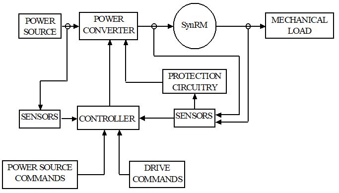
Fig. 1. SynRM drive system.
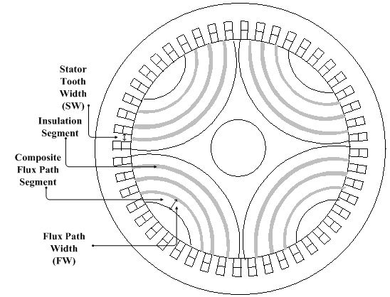
Fig. 2. ALA rotor SynRM cross-section.
Furthermore, the voltages V, V, and V represent the system input voltage vector, which accounts for the drive power electronics and associated controllers [6, 7, 8]. Also, F, is given as
| (3) |
where J is the moment of inertia of the rotor, is the friction coefficient, T is the mechanical load, and T is given as:
| (4) |
In addition, the FE formulations account for anisotropy by using a reluctivity tensor:
| (5) |
where and are the reluctivity normal and tangential components, and is the angle of the easy magnetization axis with the x-axis [7]. As such, the FE-SS module accounts for space harmonics due to material nonlinearities and machine complex geometry, time harmonics due to switching electronics, and for rotor material anisotropy [6, 7, 8] when predicting the performance characteristics of the SynRM drive system.
III. THE TAGUCHI-FE-PSO DESIGN ENVIRNOMENT
The objective of this work is to maximize the developed torque while minimizing torque ripple as well as Ohmic, switching, and core losses of the SynRM drive system (Figure 1). To optimize the design of the motor drive system, the FE-PSO environment of Figure 3 was developed. It uses the FE-SS characterization module described above to predict the performance characteristics of the SynRM drive system, which include various SynRM currents and voltage waveforms as well as the torques profile, which are used to train offline a fuzzy logic (FL) module [9]. The FL module as shown in Figure 4, consists of a fuzzification and defuzzification inference units, a knowledge base formed from a database and a rule base unit. A Sugeno type FL is used in this work and the fuzzification is implemented using double-sided Gaussian membership functions [9]. The input vector of the FL model is the design vector, I, and the output is a set of performance indicators. The FL module is incorporated within the PSO search algorithm, which is an evolutionary computation algorithm developed by Kennedy and Eberhart [10] and it mimics the social behavior of a flock of birds where information is shared among the individuals of a population. The PSO starts with an initial swarm of random particles in the search space where each particle is also assigned a randomized velocity. The velocity of each particle is dynamically updated based on the particle’s best previous position reached and the best position reached among previous generations. The PSO uses the FL module to evaluate the OF corresponding to any values of the design vector in the search space. As can be appreciated from the above, large number of FE solutions and PSO iterations are required to find an optimum design. As such, a Taguchi-FE-PSO environment, as shown in Figure 5, is developed to reduce computational time needed to reach an optimum design. At the heart of this environment is the Taguchi orthogonal arrays method. The one used in this work is of the four-level, L16 orthogonal array type [4, 5], which is used to determine the minimum number of input design parameter’s combinations required to cover the design optimization problem search space. The method assigns a range for each input design parameter. In addition, each range is divided into equal intervals.
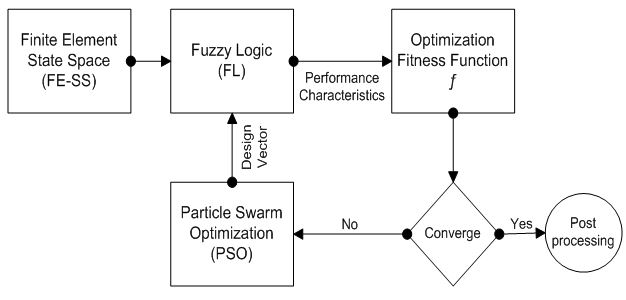
Fig. 3. FE-PSO design optimization environment.
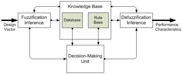
Fig. 4. Fuzzy logic module.

Fig. 5. Taguchi-FE-PSO design optimization environment.
IV. APPLICATION OF THE TAGUCHI-FE-PSO DESIGN ENVIRNOMENT AND RESULTS
As stated above, the objective of this work is to maximize the developed torque while minimizing torque ripple and losses of the SynRM drive system of Figures 1 and 2. The Taguchi-FE-PSO design optimization environment developed in this work utilizes the Taguchi four-level L16 orthogonal arrays method [4, 5] which is used to determine the minimum number of input design parameter’s combinations required to cover the design optimization problem search space. The values of the design parameters are determined in the FE-SS module that predicts the performance characteristics of the SynRM drive system, which are used to train, offline, the FL module, that is used as a system identifier in the PSO search algorithm. It should be noted here that the SynRM drive system for traction applications was implemented with both EPA Urban and Highway Federal Driving Schedules [11] (Figures 6 and 7).
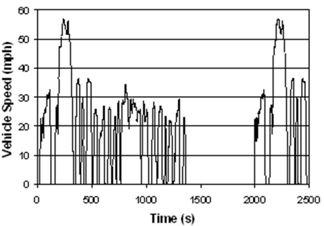
Fig. 6. Federal Urban Driving Schedule, “FUDS”.
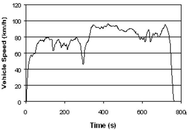
Fig. 7. Federal Highway Driving Schedule “FHDS”.
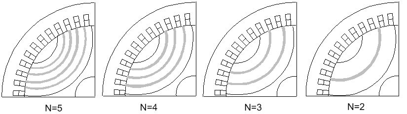
Fig. 8. Number of flux paths variation.
The Taguchi-FE-PSO design environment of Figure 5 was applied to find an optimum design for the prototype SynRM drive of Figure 1 operating at 90 Nm and 3000 rpm load conditions. In this optimization problem, the input design vector, I consists of the number of flux paths (N), the stator tooth width (SW), and the rotor flux path width (FW), shown in Figure 2. The design optimization environment starts by defining an objective function (OF). It is defined as the weighted sum of the performance indicators that include torque ripple, T, the total losses in the machine, T, and the developed torque average, T, constrained at a desired load, T:
| (6) |
where and are the weights of T and T, respectively, and is the Lagrangian multiplier.
Next, the input design parameters vector is defined as follows: P = N, represents the possible number of rotor flux paths, and it is restricted to be in the range of 2–5, due to physical design constraints of the machine. That is, the rotor has four possible designs corresponding to N = 2, 3, 4, or 5, as shown in Figure 8; P = SW, the stator tooth width; and P = FW, the rotor flux path width, shown in Figure 2. The PSO search method would require many design trials. Furthermore, the search for the optimum design would require accurate evaluation of each design vector or trial, using the FE-SS module, at relatively high computational cost. As such, the Taguchi four-level, L16, orthogonal arrays method was used to determine the minimum number of input design parameter’s combinations required to cover the design optimization problem search space. It assigns a range for each input design parameter and divides each range into equal intervals or levels designated as 1 for low, 2 for medium, 3 for high, and 4 for maximum, as given in Table 1. In addition, the search space ranges of SW and FW are given in Table 2 for each of the four possible rotor designs and were divided into equal intervals. The FE-SS module was used to compute the ALA rotor performance characteristics for the PSO trail particles of each of the 16 categories. Next, the results of the FE-SS module were used to train the corresponding adaptive neuro fuzzy inference system, ANFIS, for a category. In this work, the PSO starts by initiating 64 PSO trials or particles in each category. The output of each particle is computed by the category corresponding ANFIS. Next, the OF given in equation (5) is evaluated and compared with a preset threshold to select the winner particles. These winner particles are then cross-mutated with each other to define new trials.
Table 1: Taguchi array with three parameters
| Category # | P = N | P = SW | P = FW |
| 1 | 1 | 1 | 1 |
| 2 | 1 | 1 | 1 |
| 3 | 1 | 2 | 2 |
| 4 | 1 | 2 | 2 |
| 5 | 2 | 1 | 2 |
| 6 | 2 | 1 | 2 |
| 7 | 2 | 2 | 1 |
| 8 | 2 | 2 | 1 |
| 9 | 3 | 2 | 1 |
| 10 | 3 | 2 | 1 |
| 11 | 3 | 1 | 2 |
| 12 | 3 | 1 | 2 |
| 13 | 4 | 2 | 2 |
| 14 | 4 | 2 | 2 |
| 15 | 4 | 1 | 1 |
| 16 | 4 | 1 | 1 |
Table 2: Range of design parameters
| N | SW (in.) | FW (in.) |
| 2 | [0.09–0.16] | [0.08–0.34] |
| 3 | [0.09–0.16] | [0.08–0.32] |
| 4 | [0.09–0.16] | [0.08–0.23] |
| 5 | [0.09–0.16] | [0.10–0.18] |
The Taguchi-FM-PSO design environment of Figure 5 was applied to find an optimum design for the prototype SynRM drive of Figure 1 and Figure 2, operating at 90 Nm and 3000 rpm load conditions, and resulted in optimized design performance indicator’s values. A summary of the main results is given in Table 3, which shows the performance characteristics of the system for the initial (N = 4) and optimal (N = 5) designs, as well as the initial and final values of the design parameters SW and FW. An inspection of these results reveals that the total losses were reduced by 61%, in addition to reducing the torque ripple by 42%. Furthermore, a sample performance profile, showing the percentage torque ripple and corresponding search space, is shown in Figure 9. As expected, the complex geometry of this class of machines in addition to the electronic switching in the drive system showed an many local minima and many saddle points in the search space.
Table 3: Initial and optimal design
| Design/Parameters | Initial | Optimal | % Change |
| [N; SW (in); FW (in)] | [4;0.115;0.148] | [5;0.103;0.112] | N/A |
| Losses | 6265 W | 2401 W | –61% |
| Torque Ripple | 52% | 30% | –42% |
| Torque Average | 90 Nm | 90 Nm | N/A |
Table 4: Computational time comparison
| FE-PSO | Taguchi-FE-PSO | |
| % Computational Time | 100% | 20.4% |
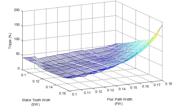
Fig. 9. Percentage torque ripple profile vs. search space.
In addition to the above, this work includes a comparison of computational time needed to solve this design optimization problem by using both, the FE-PSO approach of Figure 3 and the Taguchi-FE-PSO approach of Figure 5. The results are presented in Table 4, which shows a comparison of the normalized computational time needed for both approaches. Based on these results, it can be stated that the implementation of the Taguchi orthogonal arrays method resulted in about 80% reduction of needed computational time.
V. CONCLUSIONS
This work utilized a Taguchi orthogonal arrays method in conjunction with a particle swarm optimization search algorithm to reduce the computational time needed to solve the design optimization problem of electric motor drives for traction applications. The results of a case study involving a prototype 100 kW ALA Rotor SynRM drive for traction applications showed an improved performance characteristics and demonstrated that the use of a Taguchi orthogonal arrays method resulted in about 80% reduction of computational time needed for implementing the FE-PSO design optimization environment.
REFERENCES
[1] K. Rajashekara, “Present status and future trends in electric vehicle propulsion technologies,” IEEE J. Emerg. and Sel. Topics Power Electron., vol. 1, no. 1, pp. 3-10, Mar. 2013.
[2] N. Al-Aawar and A. A. Arkadan, “Hybrid electric vehicle characterization using generalized notion of power,” Applied Computational Electromagnetics Society (ACES) Journal, vol. 28, no. 11, pp. 1080-1087, Nov. 2013.
[3] J. M. German, Hybrid Powered Vehicles, SAE International, Warrendale, PA, 2003.
[4] R. N. Kacker, E. S. Lagergren, and J. J. Filliben, “Taguchi’s orthogonal arrays are classical designs of experiments,” J. Res. Natl. Inst. Stand. Technol., vol. 96, no. 5, 577-591, Sep-Oct. 1991.
[5] A. A. Arkadan, N. Al-Aawar, and A. O. Hariri, “EM-Taguchi module for the characterization of WAD,” IEEE Trans. on Magnetics, vol. 51, no. 3, Article 8202304, Mar. 2015.
[6] F. N. Isaac, A. A. Arkadan, A. A. Russell, and A. El-Antably, “Effects of anisotropy on the performance characteristics of an ALA synchronous reluctance motor drive system,” IEEE Trans. on Magnetics, vol. 34, no. 5, pp. 3600-3603, Sep. 1998.
[7] F. N. Isaac, A. A. Arkadan, and A. El-Antably, “Magnetic field and core loss evaluation of ALA-rotor synchronous reluctance machines taking into account material anisotropy,” IEEE Trans. on Magnetics, vol. 34, no. 5, pp. 3507-3510, Sep. 1998.
[8] A. A. Arkadan, F. N. Isaac, and O. A. Mohammed, “Parameters evaluation of axially laminated anisotropic synchronous reluctance motor drives,” IEEE Trans. on Mag., vol. 36, pp. 1950-55, Jul. 2000.
[9] T. Takagi and M. Sugeno, “Derivation of fuzzy control rules from human operator’s control action,” in IFAC Symp. Fuzzy Info., 1983.
[10] J. Kennedy and R. C. Eberhart, “Particle swarm optimization,” Proceedings of IEEE International Conference on Neural Networks, Piscataway, NJ., pp. 1942-1948, 1995.
[11] EPA, “Vehicle chassis dynamometer driving schedules. Available: online: dynamometer drive schedules, vehicle and fuel emissions testing,” US EPA. [Accessed Oct. 03, 2019].
ACES JOURNAL, Vol. 36, No. 11, 1407–1411.
doi: 10.13052/2021.ACES.J.361103
© 2021 River Publishers