Possible Leaky Wave Antennas for Propagation Therapy using SAR Analysis
Masoud Sarabi and Warren F. Perger
Department of Electrical & Computer Engineering
Michigan Technological University, Houghton, 49931, USA
msarabi@mtu.edu, wfp@mtu.edu
Submitted On: March 26, 2021; Accepted On: September 26, 2021
Abstract
This paper presents an overview of design and functionality of three novel leaky wave antennas (LWAs) that are proposed as a possible hyperthermia system using LWA logic. LWAs are best known for their interesting property of frequency scanning. This makes them appealing for beam steering applications such as biomedical hyperthermia and radar applications. Regarding the biomedical hyperthermia application, the property of beam scanning could be used for treatment of tumors found in different regions and depths of a given tissue. The proposed antennas are as follows: (1) mushroom-typed leaky wave antenna, (2) two-dimensionally (2D) periodically slotted leaky wave antenna, (3) belt-shaped leaky wave antenna. Each antenna provides distinguished advantages for hyperthermia therapy which will be discussed in the corresponding sections. For example, the belt-shaped leaky wave antenna is a conformal antenna that could follow the cylindrical shape of the patient’s neck and focus the electromagnetic beam on the neck tumors. Two-dimensional LWAs such as mushroom-typed leaky wave antennas provide more beam steering flexibility compared to 1D types such as 1D slotted leaky wave antennas.
Index Terms: hyperthermia, leaky wave antenna (LWA), mushroom-typed leaky wave antenna, 2D periodically slotted leaky wave antenna, belt-shaped leaky wave antenna.
I. INTRODUCTION
A promising therapeutic treatment for dealing with cancerous tumors, is a nonsurgical modality known as hyperthermia. Hyperthermia can be applied to a human body tissue in which the electromagnetic radiation of the near field of an antenna or applicator is exposed to that tissue and elevates the temperature of it. Hyperthermia is applied to a target tissue such that the regions other than the cancerous ones are not affected by this radiation and thus no temperature elevation should happen in the surrounding healthy regions [1, 2]. Hyperthermia is not necessarily the final treatment for cancerous tumors but could be used in combination with other treatment methods such as chemotherapy to achieve the best results [3, 4]. Hyperthermia has two types: superficial hyperthermia (SHT) and deep hyperthermia (DHT). SHT is usually used for the tumors that are found in depths of about 4 cm or less and DHT is used for tumors that are situated in regions deeper than 4 cm. Usually the frequency ranges that are used for SHT are about 915 MHz or 2.45 GHz for US and 434 MHz for Europe and Japan [5]. The efficient temperature elevation for hyperthermia treatment is between . The metabolism and the blood flow of the malignant cells are different from the normal cells and they are more vulnerable to temperature elevation. Different antenna types and beam focusing methods have been proposed in the corresponding literature. The treatment efficiency of each antenna or applicator depends on the dimensions of a tumor, depth of the tumor, size, and the intrinsic characteristics of the tissue such as conductivity. For superficial tumors, microstrip patch antennas have been used while for deep-seated tumors slot antennas have been proposed to be inserted into a tissue since for such tumors, heat needs to be transferred to the tissue depth [4]. In [8], a microwave hyperthermia system using a coaxial-slot antenna in both single and array forms has been introduced. The single antenna was used to treat a shallow tumor in the right shoulder area of a 60-year-old patient and the array applicator was used for the treatment of a tumor in the right shoulder region of a 61-year-old patient. Another literature [9] proposes a balun-free helical antenna with two different matching systems of quarter-wave network and also a -network. This system was tested upon a bovine liver tissue using the input power of 42W for a time length of 5–10 minutes. Another design has been introduced in our earlier work [10] that proposes a substrate integrated waveguide LWA for hyperthermia functionality in frequency range of 13.8–15.2 GHz which is capable of addressing superficial cancerous tumors. Antenna arrays are typically used to illuminate the beam on a tissue with higher focusing capability compared to single-antenna systems. A promising application of antenna arrays has been in imaging of the leukemia, breast cancer [17]-[42], and cardiac anomalies [43, 44]. For example, [2] introduces a hexagonal focused array that operates at 433 MHz. In this design, there is an array of patch antennas located on each side of the hexagon and the sample bio-tissue is placed at the center of this structure to be heated up. In [3], a SIGMA-Eye applicator array has been designed. The applicator system consists of three rings of dipole antennas. The best performance with this applicator array has been observed when all the antennas were in phase and fed with the same power. In [4], the authors have introduced two types of antennas that both function at the frequency of 2.45 GHz. Usually, in order to treat malignant tumors that are in-depth, antenna arrays are used. Lower working frequencies such as 915 MHz could provide a considerable heat penetration. In order to avoid having superficial skin burns, a water bolus is basically used that is placed between the antenna system and the tissue [5]. Some designs are introduced to have hyperthermia treatment for a specific part of the body. For example, in [6], a patch antenna design is used as a phased-array head and neck applicator. Based on [7] and [8] the most optimal configuration for head and neck hyperthermia is a circular array, and in [6] the same setup is used that consists of 12 antennas. This paper is organized as follows: in section II, we are going to discuss the proposed antenna structures and evaluation of their electromagnetic performances such as propagation patterns and return loss. In section III the specific absorption ratio (SAR) mechanism and heating methodology will be discussed. Section IV will contain the results and discussion, and the conclusion will be given in section V.
The state-of-the-art hyperthermia solutions use antenna arrays which have higher complexities and higher manufacture cost, while in the present work, we have proposed simple and cheap solutions for hyperthermia therapy. The design and methodology of each antenna system will be explained in the corresponding sections but in short, we have focused on planar antennas with different feeding mechanisms and structural topology which would offer diverse hyperthermia treatment depending on the geometry of the focused beams on tissue. In each study, the antenna has been designed using CST software and after calculation of the propagation patterns, return loss and power loss density, finally the SAR on a slice of tissue has been calculated. The bio-tissue has been selected from the library of materials in CST Software and the slice has been placed in close proximity to each antenna, while this whole antenna-tissue set has been considered as a closed thermal system for thermal simulations. Finally, all the SAR maps have been analyzed using a developed MATLAB code and comparisons regarding the geometry of the heated tissue regions and the corresponding areas have been summarized in tables.
II. ANTENNA STRUCTURES AND PERFORMANCE
In the following sections A, B, and C, we will introduce three antennae. For each antenna, the main features such as return loss, propagation patterns, and directivity will be discussed. The functionality of each antenna as a candidate hyperthermia system will be investigated using SAR analysis results and the comparison with internationally accepted SAR values for biomedical instruments as a numerical validation tool for each antenna system. Investigation of the SAR results illuminate at which frequency points each antenna system tends to generate focal beams and at which frequencies wider areas of bio-tissues can be affected by heat. It is significant to have an estimate of the dimensions of the tissue areas affected by temperature elevation, which is calculated in using MATLAB as discussed in section IV.
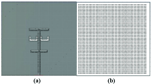
Fig. 1. The structure of 2D mushroom-type leaky wave antenna: (a) back side, (b) front side.
A. 2D mushroom-type leaky wave antenna
The mushroom-type leaky wave antenna is composed of a ground plane of a perfect electric conductor (PEC) with dimensions , a substrate of TMM 10i with permittivity of , the same planar dimensions as the ground plane and the thickness of =. There are 47 by 48 square cells that are each connected to the ground plane by via. The ground plane has two U-shaped slots and a microstrip line. This antenna is fed through the ground plane using an aperture coupling feed mechanism. The excitation signal of the antenna is a default gaussian signal used in CST Microwave Studio software within the frequency range of to . The benefit of the aperture coupling feed is that it minimizes the spurious radiation. The advantage of the rectangular PEC cells is that they form a mushroom structure which suppresses surface waves and hence improves the radiation.

Fig. 2. (a) Propagation pattern of mushroom-type LWA at 2.5 GHz, (b) Return loss graph.
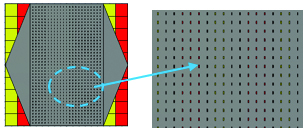
Fig. 3. The structure of 2D periodically slotted leaky wave antenna.
As we can see on Figure 2 (a), there are several beams with directivity of about 5.44 dBi at f = 2.5 GHz. The return loss graph on Figure 2 (b), illustrates three decent frequency bands of operation, B1, B2, and B3 which have return loss values of less than -10 dB. For the two frequency points of =2.15 GHz and = 2.5 GHz, the mushroom-type leaky wave antenna shows return loss values of less than -18 dB. Especially, the frequency point of about 2.5 GHz is a common frequency for many medical instruments that work in ISM bands.
B. Two dimensionally periodically slotted leaky wave antenna
In this type of LWA shown on Figure 3, there is a ground plane of PEC with dimensions of and two different substrates, Rogers RT6010 with permittivity and RO3003 with permittivity . Each individual substrate cell is and the whole substrate consists of 100 cells shown in red and yellow. The authors believe that by using two different columns of higher permittivity and lower permittivity, one could achieve better propagation characteristics such as having more beam directivity, that could be of high interest in biomedical applications that need considerable beam focusing. Figure 4 (a) shows that beam directivities of up to 12.3 dBi have been achieved. The superstrate is a PEC which has 39 by 23 slots. The slots cause the leakage mechanism in this antenna and give the antenna the capability to produce scanned beams over a wide range of angles from broadside to end-fire directions. There are two tapered feeding lines connected to both sides of the superstrate. The purpose of tapered feedlines is for having better impedance matching properties which lead to more decent return loss values.
Figure 4 (a) illustrates the propagation pattern of this antenna at 2.45 GHz with highly directive beams, and Figure 4 (b) shows the return loss graph for frequency range of 2-3.6 GHz. The antenna shows very decent impedance matching around 2.5 GHz, 2.65 GHz, 2.85 GHz, and 3.55 GHz as marked by points , , and on Figure 4 (b).
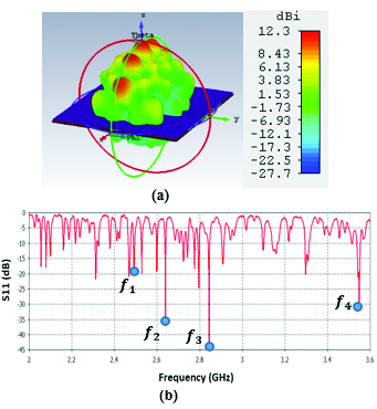
Fig. 4. (a) Propagation pattern of 2D periodically LWA at 2.45 GHz, (b) Return loss graph.
C. Belt-shaped leaky wave antenna
In this section, we would like to introduce the belt-shaped leaky wave antenna for the first time. In the belt-shaped leaky wave antenna, we actually have a 1D slotted antenna with a tapered microstrip feeding mechanism as shown in Figure 5. In this structure, the main motivation is to have a conformal antenna that could fit the shape of the head or neck to focus on cancerous tumors of these regions. In the simulation environment, the tissue was placed at the center of the antenna, which is shown as violet cylinder on Figure 5 and the thermal distribution patterns of the given tissue were studied. The substrate is TMM10 with a permittivity value of . In LWAs, we consider the mode as a fast mode, i.e., (c=speed of light) and plugging it into the Floquet formula (1)
| (1) |
Will give the following inequality (2):
| (2) |
And solving for will lead to the following design condition (3):
| (3) |
In simpler words, the mode , which is considered as a fast mode, enforces some design principles on LWAs. This fast mode actually excites other slow modes and leads to wave propagation from the antenna. A portion of the EM wave leaks out of each slot as the wave travels along the structure. The frequency range for simulation is to . This antenna could be designed with a considerably thin substrate to increase the bendability of it.
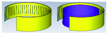
Fig. 5. The structure of ring-shaped leaky wave antenna.
Figure 6 (a) illustrates the propagation pattern of this antenna at 2.45 GHz as well as the return loss graph. The propagation pattern at 2.45 GHz looks like a fan beam rather than pencil beam which is applicable to hyperthermia treatment scenarios that need larger tissue area is to be targeted with temperature elevation. Figure 6 (b), illustrates the return loss graph for this antenna. Sample frequency points of, , , and correspond to 2.45 GHz, 2.9 GHz, 3.7 GHz, 4 GHz, and 5.2 GHz which show very decent return loss values such as –20 dB or –25 dB.
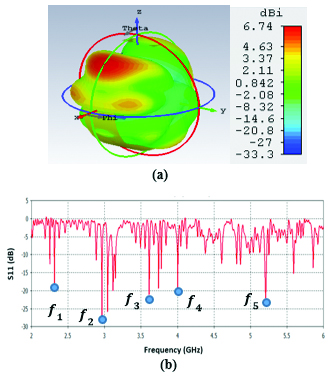
Fig. 6. (a) Propagation pattern of ring-shaped LWA at 2.45 GHz, (b) Return loss graph.
III. SAR AND METHODOLOGY
SAR gives a measure of the rate of the absorption of energy by a human body tissue. This measure can be expressed by electric field intensity or temperature variation. SAR is expressed as equation (4),
| (4) |
In which, is the conductivity of tissue, is the electric field intensity of the incident wave and is the density of tissue. In other words, is defined as the average power loss density mathematically expressed as in density volume of a given tissue in human body (. It is important to note that a given tissue is composed of four layers: bone, muscle, fat, and skin. In the simulation steps of CST software, we can set field monitors for calculation of power loss density as explained in the SAR formula and finally the software is able to give us the SAR as thermal maps expressed in W/Kg (Watt per Kilogram of a tissue). There are two main methods for SAR analysis in CST software which are average SAR and point SAR. In the average SAR, basically a cube of 1 g or 10 g is considered and power loss density is calculated for this whole 3D region. In point SAR, the software allocates a SAR value to a given point without doing any averaging. Table 1 shows the maxima of the mass averaged SAR values that are acceptable world-wide [12]. The results of this work are based on US and Canada SAR standards suggesting that the acceptable average SAR values are to be about 1.6 W Kg or lower than that, as summarized in Table 1.
Table 1: SAR guide
| Typical Standards | SAR Limit ( |
| US & Canada | 1.6 ) averaged over 1 g of tissue |
| EU, Japan, Brazil | 2 averaged over 10 g of tissue |
The research regarding the most optimal antenna solutions for hyperthermia treatment is very extensive simply because the thermal characteristics of a given tissue differs from patient to patient and from tissue to tissue. The Pennes bioheat equation interestingly connects the temperature (T) and the applied energy distribution using biomedical properties of a tissue [13] as expressed by equation (5)
| (5) |
in which, is the specific heat capacity, is temperature, t is the time, is volume density, is the metabolic heat rate, is the specific absorption ratio, is the blood mass density, is the specific heat capacity of blood, is the blood perfusion rate, and is the blood temperature which is about . By applying RF electromagnetic field, we could derive equation 4 which is an approximated solution of the Pennes equation for our study. We developed an image processing tool in MATLAB that is able to extract the 2D image of tissue areas affected by maximal SAR values in each of the three antenna systems. The MATLAB code, gives us a good insight into the geometry of the heat dissipation on tissue areas and understanding how frequency variation could affect the SAR values.

Fig. 7. SAR map [W/kg] of Mushroom LWA on kidney tissue at 2 GHz: (a) 1 g average SAR, (b) point SAR.
IV. RESULTS AND DISCUSSION
To study the capability of each antenna system as a potential hyperthermia system, 1 g average SAR and point SAR were calculated. In point SAR study, the local SAR value is calculated but without any mass or volume averaging. In the average SAR study after the calculation of the local SAR, this value is normalized by a fixed volume. In this study, the tissue was placed in the near field of each antenna. Each antenna system was excited by gaussian excitation and the solver used was Time Domain Solver of the CST software to calculate the EM results including propagation patterns, return loss, VSWR, and the power loss densities at the given frequencies. After the EM simulation was done for each antenna, then the power loss values for targeted frequency points were calculated as a post-processing step. Based on the power loss values, the Thermal Solver of CST calculated the SAR maps on bio-tissues, where there was the option to choose between 1 g average SAR and point SAR. The main frequency of operation based on ISM regulation is around 2.45 GHz for medical instruments. However, in our study, frequency values of up to 6 GHz have been considered for simulation, in order to have a better understanding of how each antenna system operates in higher frequency bands for hyperthermia functionality. In the following section, the SAR analysis results are illustrated. There are eight figures for each antenna. Figures labeled with (a) show the average SAR results and figures labeled with (b) show the point SAR results. SAR values are summarized in the corresponding tables for each set of results. The tissue area is a constant number of for the mushroom type, and 2D periodically slotted leaky wave antennas. The results for the mushroom-type leaky wave antenna have been shown on the Figures 7–10. We can see how the geometry of the heat distribution changes by shifting from 2 GHz to 2.45 GHz and 3 GHz up to 3.6 GHz. At 2.45 GHz, the pattern looks like a clover. Such SAR patterns could be suitable for targeting tissues which have several adjacent tumor regions. Figure 7 shows the SAR analysis for the frequency of 2 GHz. The maximal SAR value is about 1.26 W Kg.

Fig. 8. SAR map [W/kg] of Mushroom LWA on kidney tissue at 2.45 GHz: (a) 1 g average SAR, (b) point SAR.
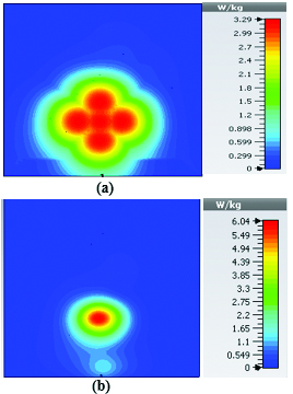
Fig. 9. SAR map [W/kg] of Mushroom LWA on kidney tissue at 3 GHz: (a) 1 g average SAR, (b) point SAR.
Figure 8 shows the SAR analysis for the frequency of 2.45 GHz. The maximal SAR value is about 1.63 W Kg. We can observe that by frequency shift of only about 450 MHz, the main beam of the mushroom-type leaky wave antenna changes its direction.
Table 2: SAR values for mushroom-type leaky wave antenna
| Frequency | 1g Average SAR | Point SAR |
| (GHz) | [W/kg] | [W/kg] |
| 2 | 1.26 | 2.3 |
| 2.45 | 1.63 | 2.63 |
| 3 | 3.29 | 6.04 |
| 3.6 | 2.66 | 4.74 |
By switching to frequencies 3 GHz and 3.6 GHz, we can observe that both the average SAR and point SAR maps illustrate more focal behavior in heat dissipation. Due to the skin effect in microwave frequencies, the penetration depth of the electromagnetic waves in the corresponding bio-tissue decreases as frequency increases and the SAR maps verify this principle.
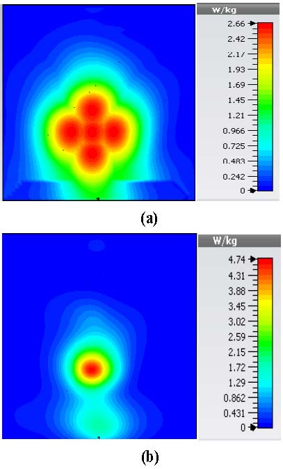
Fig. 10. SAR map [W/kg] of Mushroom LWA on kidney tissue at 3.6 GHz: (a) 1 g average SAR, (b) point SAR.

Fig. 11. SAR map [W/kg] of 2D periodically slotted LWA on kidney tissue at 2 GHz: (a) 1 g average SAR, (b) point SAR.
Table 2 summarizes the results of SAR analysis for the mushroom-type leaky wave antenna. In this section, we can observe the SAR analysis results for 2D periodically slotted leaky wave antenna. Starting at the frequency of 2 GHz, the SAR results show a fuzzy heat distribution pattern.
At 2.45 GHz, we can see two cross-shaped regions with maximal SAR value of 0.943 W Kg. By switching from 2.45 GHz to 3 GHz the affected area transforms itself from a homogeneously heated region (Figure 12) to a focused SAR pattern (Figure 13), which could be applicable to a scenario where a more focused beam is required for hyperthermia treatment.
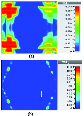
Fig. 12. SAR map [W/kg] of 2D periodically slotted LWA on kidney tissue at 2.45 GHz: (a) 1 g average SAR, (b) point SAR.

Fig. 13. SAR map [W/kg] of 2D periodically slotted LWA on kidney tissue at 3 GHz: (a) 1 g average SAR, (b) point SAR.

Fig. 14. SAR map [W/kg] of 2D periodically slotted LWA on kidney tissue at 3.6 GHz: (a) 1 g average SAR, (b) point SAR.
This section illustrates the SAR results for the belt-shaped leaky wave antenna. In this case, the tissue geometry has been chosen to be a cylinder with the inner radius of 73 mm and outer radius of 76 mm, and height of 60 mm. The surface area of this geometry is . As we can see on Figures 15–18, the geometry of the heated area changes from extended heat distribution in Figure 15 to a more focused heat pattern on Figure 18.

Fig. 15. SAR map [W/kg] of belt-shaped LWA on kidney tissue at 2 GHz: (a) 1 g average SAR, (b) point SAR.
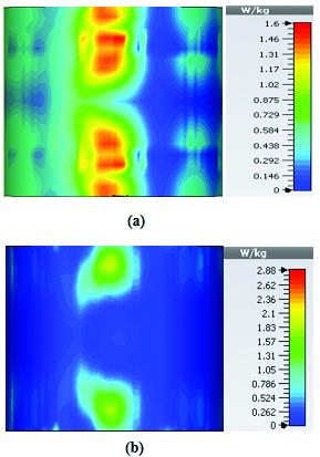
Fig. 16. SAR map [W/kg] of belt-shaped LWA on kidney tissue at 2.45 GHz: (a) 1 g average SAR, (b) point SAR.
Table 3: SAR values for of 2D periodically slotted
| Frequency | 1g Average SAR | Point SAR |
| (GHz) | [W/kg] | [W/kg] |
| 2 | 1.22 | 9.72 |
| 2.45 | 0.943 | 11.3 |
| 3 | 0.768 | 10.2 |
| 3.6 | 1.36 | 19.6 |
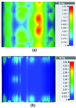
Fig. 17. SAR map [W/kg] of belt-shaped LWA on kidney tissue at 3 GHz: (a) 1 g average SAR, (b) point SAR.
For the belt-shaped leaky wave antenna, all the calculated average SAR values are equal to or less than 1.6 W Kg per 1 g of the bio-tissue. For frequencies 2 GHz, 2.45 GHz, 3 GHz, and 3.6 GHz, the average SAR values are respectively 1.41 W Kg, 1.6 W Kg, 1.51 W Kg, and 1.61 W Kg.

Fig. 18. SAR map [W/kg] of belt-shaped LWA on kidney tissue at 3.6 GHz: (a) 1 g average SAR, (b) point SAR.
Table 4 summarizes the SAR analysis results for the belt-shaped leaky wave antenna.
Table 4: SAR values for belt-shaped leaky wave antenna
| Frequency | 1g Average SAR | Point SAR |
| (GHz) | [W/kg] | [W/kg] |
| 2 | 1.41 | 2.26 |
| 2.45 | 1.6 | 2.88 |
| 3 | 1.51 | 3.56 |
| 3.6 | 1.61 | 4.66 |
In the following section, we are going to discuss the SAR results after applying image processing code to them. The MATLAB code is able to keep the areas with maximal SAR values while filtering out the other regions and calculate the values of these areas in . The logic of this program follows the RGB coding, in which the thresholds for red, blue, and green colors need to be set carefully. Setting those thresholds could define what range of “red” is acceptable for the acceptable SAR margins, e.g., around 1.6 W Kg for hyperthermia applications. The range of numbers 0-255 are allocated to colors and each color can be defined a mixture of red, blue, and green, thus we could attribute an array of three numbers to any color. The summary of the processing steps in the CST and MATLAB code are as follows:
1. EM simulation and preliminary SAR analysis in CST Software tool.
2. SAR maps loaded in MATLAB from CST.
3. Calculation of the number of all pixels.
4. Setting RGB thresholds.
5. Filtering out the non-red areas.
6. Calculation of the areas with maximal SAR values using
Table 5: Heated tissue areas at
| Antenna type | Heated area in |
| Mushroom-type LWA | 1.998484e+03 |
| 2D periodically slotted LWA | 2.389691e+03 |
| Ring-shaped LWA | 3.191384e+02 |
The first step of the processing steps led to the EM simulations and the previously discussed SAR maps and steps 2 to 6 discuss the processing steps in MATLAB. The following MATLAB code is developed for the extraction of the tissue areas affected by maximal SAR values and the calculation of the area of such regions in .
Figures 19 and 20 illustrate the application of the MATLAB code on the SAR maps of the mushroom-type and 2D periodically slotted leaky wave antennas. We can observe that only the regions with maximal SAR values of about 1.63 W Kg on Figure 19 and 0.943 W Kg on Figure 20 have been preserved.
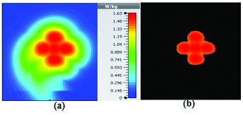
Fig. 19. SAR map [W/kg] of mushroom LWA on kidney tissue at 2.45 GHz: (a) 1 g average SAR map, (b) filtered SAR map.
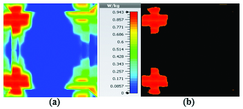
Fig. 20. SAR map [W/kg] of 2D periodically slotted LWA on kidney tissue at 2.45 GHz: (a) 1 g average SAR map, (b) filtered SAR map.
Table 5 summarizes the overall calculated areas on tissues that are exposed to maximal SAR values in the three proposed antenna systems at the frequency of 2.45 GHz.
V. DISCUSSION AND CONCLUSIONS
Three novel leaky wave antennas for application in microwave hyperthermia were investigated. Each of these microwave systems offer some distinguished frequency scanning and beam focusing properties with proven efficiency for hyperthermia applications, which make them appealing for treatment of different cancerous tumors. For the mushroom-type leaky wave antenna, the top PEC plates cause an effective suppression of the surface waves that lead to the increase of the antenna efficiency. Looking at the corresponding SAR maps for the frequency points of 2 GHz and 2.45 GHz, we can observe that the antenna shows decent focused heat distribution on the tissue while reaching the accepted standard SAR values of less than 1.6 W Kg. For the 2D periodically slotted leaky wave antenna, we could reach high beam directivities of up to 12.3 dBi which make this antenna a very good candidate for hyperthermia treatment. In addition to the structure of the two-dimensionally placed slots causes the beam angle to have more scanning flexibility which leads to wide ranges of angles from broadside to end-fire. This antenna is capable of changing the geometry of SAR from focused shape to an extended shape with a narrow frequency shift of 450 MHz. For the belt-shaped leaky wave antenna the conformal shape of the structure makes it convenient for installation of the antenna in body regions such the neck where tumors could develop. For this antenna, it is best to use a very thin substrate to achieve two goals: (1) reducing surface waves and (2) increasing the antenna bendability. Potentially belt-shaped leaky wave antennas with two-dimensionally placed slots could provide more beam angle flexibility and control over beam displacement, which could be of interest for future works.
REFERENCES
[1] H. Trefna and M. Persson, “Heating of deep seated tumours using microwaves radiation,” ACES Conference 2007, Verona, Italy, Mar. 19-23, 2007.
[2] W. Xi, B. Liu, and Binkai Xu, “Theoretical evaluation of high frequency microwave ablation applied in cancer therapy,” Applied Thermal Engineering, vol. 107, pp. 501-507, 2016.
[3] J. Mallorqui, A. Broquetas, L. Jofre, and A. Cardama, “Non-invasive active thermometry with a microwave tomographic scanner in hyperthermia treatments,” Applied Computational Electromagnetics Society (ACES) Journal, vol. 7, pp. 121-127, 1992.
[4] H. Xiaoping, W. Geyi, and S. Wang, “A hexagonal focused array for microwave hyperthermia: optimal design and experiment,” IEEE Antennas and Wireless Propagation Letters, vol. 15, pp. 56-59, 2015.
[5] G. C. Van Rhoon and J. van der Zee, “Hyperthermia a treatment for cancer: maturation of its clinical application,” Polish Journal of Environmental Studies vol. 15.4A, pp. 11-15, 2006.
[6] P. F. Tumer, T. Schaefermeyer, M. Latta, R. Lauritzen, and D. T. Sells, “3-D heating pattern steering using the sigma eye phased array applicator controlled by a modified BSD-2000 hyperthermic oncology,” edited by C. Franconi et al. (Tor Vergata Post Graduate School of Medical Physics, Rome), pp. 571-573, 1996.
[7] O. B. Debnath, K. Ito, K. Saito, and M. Uesaka, “Design of invasive and non-invasive antennas for the combination of microwave-hyperthermia with radiation therapy,” 2015 IEEE MTT-S 2015 International Microwave Workshop Series on RF and Wireless Technologies for Biomedical and Healthcare Applications (IMWS-BIO). IEEE, 2015.
[8] R. V. Sabariego, L. Landesa, and F. Obelleiro, “Synthesis of an array antenna for hyperthermia applications,” IEEE Transactions on Magnetics, vol. 36, no. 4, pp. 1696-1699, 2000.
[9] M. M. Paulides, F. Jurriaan, N. Chavannes, and G. C. Van Rhoon, “A patch antenna design for application in a phased-array head and neck hyperthermia applicator,” IEEE Transactions on Biomedical Engineering, vol. 54, no. 11, pp. 2057-2063, 2007.
[10] M. M. Paulides, S. H. J. A. Vossen, A. P. M. Zwamborn, and G. C. Van Rhoon, “Theoretical investigation into the feasibility to deposit RF energy centrally in the head and neck region,” Int. J. Rad. Onc. Biol. Phys., vol. 63, pp. 634-642, 2005.
[11] M. M. Paulides, J. F. Bakker, A. P. M. Zwamborn, and G. C. Van Rhoon, “A head and neck hyperthermia applicator: Theoretical antenna array design,” Int. J. Hyperthermia, vol. 23, no. 1, pp. 59-67, 2007.
[12] H. Luyen, S. C. Hagness, and N. Behdad, “A balun-free helical antenna for minimally invasive microwave ablation,” IEEE Transactions on Antennas and Propagation, vol. 63.3, pp. 959-965, 2015.
[13] M. Sarabi and W. Perger, “A Novel Leaky Wave Antenna for Hyperthermia,” In 2019 IEEE Texas Symposium on Wireless and Microwave Circuits and Systems (WMCS). IEEE, pp. 1-4, 28 Mar. 2019.
[14] T. Hamed and M. Maqsood, “SAR calculation & temperature response of human body exposure to electromagnetic radiations at 28, 40 and 60 GHz mmWave frequencies,” Progress in Electromagnetics Research, vol. 73, pp. 47-59, 2018.
[15] T. Wittig, “SAR overview,” www.cst.com, accessed Nov. 25, 2016.
[16] https://www.sciencedirect.com/topics/medicine-and-dentistry/specific-absorption-rate.
[17] D. Colton and P. Monk, “A new approach to detecting leukemia: Using computational electromagnetics,” IEEE Trans. Comput. Sci. Eng., vol. 2, pp. 46-52, winter 1995.
[18] P. M. Meaney, M. W. Fanning, D. Li, S. P. Poplack, and K. D. Paulsen, “A clinical prototype for active microwave imaging of the breast,” IEEE Trans. Microwave Theory Tech., vol. 48, pp. 1841-1853, Nov. 2000.
[19] W. C. Chew and J. H. Lin, “A frequency-hopping approach for microwave imaging of large inhomogeneous bodies,” IEEE Microwave Guided Wave Lett., vol. 5, pp. 439-441, Dec. 1995.
[20] O. S. Haddadin and E. S. Ebbini, “Imaging strongly scattering media using a multiple frequency distorted Born iterative method,” IEEE Trans. Ultrason., Ferroelect., Freq. Contr., vol. 45, pp. 1485-1496, Nov. 1998.
[21] Q. Fang, P. M. Meaney, and K. D. Paulsen, “Microwave image reconstruction of tissue property dispersion characteristics utilizing multiple-frequency information,” IEEE Trans. Microwave Theory Tech., vol. 52, pp. 1866-1875, Aug. 2004.
[22] P. M. Meaney, K. D. Paulsen, A. Hartov, and R. C. Crane, “An active microwave imaging system for reconstruction of 2-D electrical property distributions,” IEEE Trans. Biomed. Imag., vol. 42, pp. 1017-1026, Oct. 1995.
[23] K. D. Paulsen and P. M. Meaney, “Compensation for nonactive array element effects in a microwave imaging system: Part I—Forward solution vs. measured data comparison,” IEEE Trans. Med. Imag., vol. 18, pp. 496-507, June 1999.
[24] P. M. Meaney, K. D. Paulsen, M. W. Fanning, and A. Hartov, “Nonactive antenna compensation for fixed-array microwave imaging: Part II—Imaging results,” IEEE Trans. Med. Imag., vol. 18, pp. 508-518, Jun. 1999.
[25] P. M. Meaney, K. D. Paulsen, A. Hartov, and R. K. Crane, “Microwave imaging for tissue assessment: Initial evaluation in multitarget tissue-equivalent phantoms,” IEEE Trans. Biomed. Eng., vol. 43, pp. 878-890, Sep. 1996.
[26] E. C. Fear, S. C. Hagness, P. M. Meaney, M. Okieniewski, and M. Stuchly, “Enhancing breast cancer detection using near field imaging,” IEEE Microwave Magazine, pp. 48-56, Mar. 2002.
[27] S. C. Hagness, A. Taflove, and J. E. Bridges, “Two-dimensional FDTD analysis of a pulsed microwave confocal system for breast cancer detection: fixed-focus and antenna-array sensors,” IEEE Trans. Biomed. Eng., vol. 45, pp. 1470-1479, Dec. 1998.
[28] S. C. Hagness, A. Taflove, and J. E. Bridges, “Three-dimensional FDTD analysis of a pulsed microwave confocal system for breast cancer detection: design of an antenna-array element,” IEEE Trans. Antennas Propagat., vol. 47, pp. 783-791, May 1999.
[29] X. Li and S. C. Hagness, “A confocal microwave imaging algorithm for breast cancer detection,” IEEE Microwave Wireless Comp. Lett., vol. 11, pp. 130-132, Mar. 2001.
[30] E. Fear and M. Stuchly, “Microwave system for breast tumor detection,” IEEE Microwave Guided Wave Lett., vol. 9, pp. 470-472, Nov. 1999.
[31] E. C. Fear and M. A. Stuchly, “Microwave detection of breast cancer,” IEEE Trans. Microwave Theory Tech., vol. 48, pp. 1854-1863, Nov. 2000.
[32] X. Yun, E. C. Fear, and R. H. Johnston, “Compact antenna for radar-based breast cancer detection,” IEEE Trans. Antennas and Propagation, vol. 53, no. 8, pp. 2374-2380, Aug. 2005.
[33] S. C. Hagness, A. Taflove, and J. E. Bridges, “Wideband ultralow reverberation antenna for biological sensing,” Electronic Lett., vol. 33, no. 19, pp. 1594-1595, Sep. 1997.
[34] M. A. Hernandez-Lopez, M. Pantoja, M. Fernandez, S. Garcia, A. Bretones, R. Martin, and R. Gomez, “Design of an ultra-broadband V antenna for microwave detection of breast tumors,” Microw. Opt. Tech. Lett., vol. 34, no. 3, pp. 164-166, Aug. 2002
[35] E. C. Fear and M. A. Stuchly, “Microwave breast tumor detection: Antenna design and characterization,” IEEE Antennas Propag. Symp. Dig., vol. 2, pp. 1076-1079, 2000.
[36] X. Li, S. C. Hagness, M. K. Choi, and D. W. W. Choi, “Numerical and experimental investigation of an ultrawideband ridged pyramidal horn antenna with curved launching plane for pulse radiation,” IEEE Antennas Wireless Propag. Lett., vol. 2, pp. 259-262, 2003.
[37] X. Yun, E. C. Fear, and R. H. Johnston, “Radarbased microwave imaging for breast cancer detection: Tumor sensing with cross-polarized reflections,” IEEE Antennas Propag. Society Symp. Dig., vol. 3, pp. 2432-2435, 2004.
[38] C. J. Shannon, E. C. Fear, and M. Okoniewski, “Dielectric-filled slotline bowtie antenna for breast cancer detection,” Electronics Letters, vol. 41, no. 7, Mar. 2005.
[39] J. M. Sill and E. C. Fear, “Tissue sensing adaptive radar for breast cancer detection: a study of immersion liquid,” Electronics Letters, vol. 41, no. 3, pp. 113-115, Feb. 2005.
[40] J. M. Sill and E. C. Fear, “Tissue sensing adaptive radar for breast cancer detection: preliminary experimental results,” IEEE MTT-S Int. Microwave Symp. Dig., Long Beach, CA, Jun. 2005.
[41] J. M. Sill and E. C. Fear, “Tissue sensing adaptive radar for breast cancer detection—experimental investigation of simple tumor models,” IEEE Trans. Microwave Theory Tech., vol. 53, no. 11, pp. 3312-3319, Nov. 2005.
[42] C. Furse, “A survey of phased arrays for medical applications,” Applied Computational Electromagnetics Society (ACES) Journal, vol. 21, no. 3, p. 365, 2006.
[43] S. Y. Semenov, A. E. Bulyshev, A. E. Souvorov, R. H. Svenson, Y. E. Sizov, V. Y. Borisov, V. G. Posukh, I. M. Kozlov, A. G. Nazarov, and G. P. Tatsis, “Microwave tomography: theoretical and experimental investigation of the iteration reconstruction algorithm,” IEEE Trans. Micr. Theory Tech., vol. 46, pp. 133-141, Feb. 1998.
[44] S. Y. Semenov, R. H. Svenson, A. E. Bulyshev, A. E. Souvorov, A. G. Nazarov, Y. E. Sizov, V. G. Posukh, and A. Pavlovsky, “Threedimensional microwave tomography: initial experimental imaging of animals,” IEEE Trans. Biomed. Eng., vol. 49, pp. 55-63, Jan. 2002.
BIOGRAPHIES

Masoud Sarabi has received his PhD in Electrical Engineering from the Michigan Tech university in 2021. His research interests are antenna design for biomedical hyperthermia, beamformers, and FMCW radar systems for road safety applications.

Warren F. Perger is a professor of Electrical and Computer Engineering department at Michigan Tech university and has been a faculty member since 1987.
ACES JOURNAL, Vol. 36, No. 10, 1335–1346.
doi: 10.13052/2021.ACES.J.361010
© 2021 River Publishers