Planar Magnetic Integration Design Based on LLC Resonant Converter
Xianming Deng, Kang Zheng, Yanxing Gu, Ankang Zhang, and Zhen Jia
Jiangsu Province Laboratory of Mining Electric and Automation, China University of Mining and Technology, Xuzhou 221116, China
xmdengcumt@126.com, K_Zheng@cumt.edu.cn
Submitted On: March 30, 2021; Accepted On: September 29, 2021
Abstract
High power density and high efficiency is a major trend in the development of power converters. The main measure to reduce the size of power converter is to improve the working frequency, and the limiting factor is the size of magnetic components. With the development of new semiconductor devices, the working frequency of power converters has been significantly improved, which gives us the opportunity to apply printed circuit board (PCB) winding planar magnetics. Compared with the traditional high frequency magnetics, planar magnetics not only reduce the size of the magnetic components effectively but also improve reliability through repeatable automated manufacturing, which is convenient for large-scale production. Magnetic integration is another method to reduce the size of the power converter. In this paper, a new magnetic structure based on PCB winding is proposed, which integrates inductance and transformer into one component. And the inductor can be independent of the transformer. In this structure, the inductance of inductor and excitation inductance of transformer can be easily controlled by changing the number of winding turns or the length of the air gap. A 20-W 200-kHz half-bridge LLC resonant converter with a peak efficiency of 94.9% is built to verify the feasibility of the designed planar magnetic integrated structure.
Index Terms: High frequency, printed circuit board (PCB) transformer, magnetic integration, LLC resonant converter.
I. INTRODUCTION
Nowadays, power electronic converters with high power density and high efficiency play a significant role in data center, aerospace, communication, and other fields. As an important part of power converter, the magnetic components including inductor and transformer are actually the limitation to reduce the size and weight of the power converter system. In addition, the production process of traditional magnetic components is complex and labor-intensive, which has become an impediment to the automatic production of power electronic converters.
In recent years, with the rapid development of printed circuit boards (PCBs), low-altitude power electronic converter has become a research hotspot. Planar magnetic structure can not only reduce the size of magnetic components but also improve the reliability through repeatable automatic manufacturing and better control of parasitic parameters. However, at low operating frequency, the cost and excessive winding turns limit the application of PCB magnetic components in power converters [1–5].
With the development of power electronics, the working frequency of the power converter increases to hundreds of kilohertz, even megahertz. At higher switching frequency, it can not only reduce the size of magnetic components but also reduce the coil turns of magnetic components, making PCB winding planar magnetic components more practical. In [6], the transformer on 65-W flyback circuit adopts PCB planar transformer. In [7] and [8], the application of PCB transformer in LLC resonant converter can significantly reduce the size of the converter and improve the power density.
Although planar magnetic components have many advantages, there are still many problems, such as multiple magnetic components and large volume. Fortunately, magnetic integration technology is an effective method to solve the above problems. Through magnetic integration, multiple magnetic components can be integrated into one magnetic component, which can effectively reduce the number of magnetic components of power converter and improve the power density.
In order to reduce the number of magnetic components and the size of the power converter, several methods of magnetic integration are often adopted. A common method is to realize the inductance function through the leakage inductance of the transformer. Several theoretical methods have been proposed to design leakage inductance of transformers. Some of them use low permeability materials as additional magnetic circuit, resulting in increased leakage inductance [9–11]. However, this will change the structure of the transformer and make its production process more complex. Due to the characteristics of low permeability materials, the core loss of magnetic components will increase and the overall efficiency of the converter will decrease. In addition, it is also popular to wind the primary winding and the secondary winding separately to obtain the required leakage inductance [12–14]. This method can lead to serious electromagnetic interference (EMI) problems, additional eddy current losses, and increased AC losses in the windings. In addition, due to the low profile characteristics of the winding transformer on PCB, this structure is difficult to be applied to it bib15 .
In this paper, a novel winding structure based on planar core is proposed. The inductor and transformer are integrated through an EI planar core, and they are decoupled. With this structure, the excitation inductance of the transformer and the inductance of the inductor can be adjusted by the air gap of the core or the number of turns of the winding. Because the leakage inductance of the transformer is not used as inductance, the EMI and eddy current loss are effectively reduced.
The structure of this paper is as follows. In Section II, a new type of magnetic integrated structure including inductor and transformer is proposed, the equivalent model is established, and the decoupling mechanism and calculation formula are deduced. In Section III, magnetic integrated components are applied to half-bridge LLC resonant transformer and the selection formula of planar core size is derived. In Section IV, simulation parameters of half-bridge LLC resonant converter are determined, and the simulation analysis of magnetic integrated components is carried out. In Section V, the experimental verification is carried out. Section VI summarizes the whole paper.
II. STRUCTURE AND ANALYSIS OF PLANAR MAGNETIC INTEGRATION
A. Planar magnetic integration of inductor and transformer
The structure of the inductor integrated with the transformer is shown in Figure 1. In order to effectively use the magnetic core and decouple the inductor and transformer, the resonant inductor is wound around the side legs of the magnetic core, the primary and secondary sides of transformer are wound around the middle leg of the magnetic core, and air gaps of the same length are opened for the three magnetic legs.
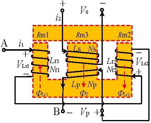
Fig. 1. Structure diagram of planar magnetic integration.
In Figure 1, N and N are the turns of primary and secondary windings of the transformer, N and N are the turns of the inductor windings around the left and right poles of the magnetic core, L and L are the self-inductance of the primary and secondary windings of the transformer, respectively, L and L are the inductance of windings around the respective side legs, the sum of L and L inductance is the inductance of resonant inductance L, V and V are the inductance voltages of the left and right legs, respectively, V and V are the voltages of primary and secondary windings of the transformer, respectively, R, R, and R are the magnetoresistance of two side legs and the middle leg, respectively, and , , and are the magnetic flux generated by the left and right column windings and the magnetic flux generated by the transformer winding, respectively.
In the design, three cylinders of the magnetic core have air gaps with the same length. For the EI-type magnetic core, the area of the column is the sum of the areas of the two side legs:
| (1) |
In formula (1), R is the air gap magnetoresistance of the middle leg of the magnetic core. According to the magnetic circuit of the magnetic integrated element, the equivalent magnetic circuit diagram is obtained, as shown in Figure 2. In this figure, , , and , respectively, represent the magnetic flux of the two side legs and the center leg of the magnetic core. Ni, Ni, Ni, and Ni, respectively, represent the magnetic potential of the inductor windings of the two side legs, and the magnetic potential of the primary and secondary side windings of the transformer.
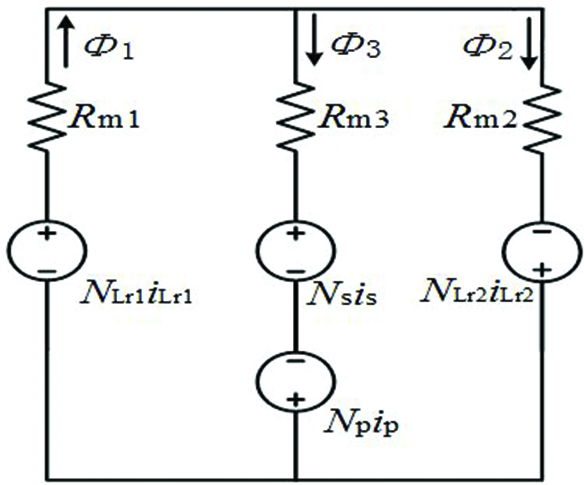
Fig. 2. Equivalent diagram of magnetic circuit.
As shown in the above design structure, the total magnetic flux generated by the inductor winding on the side leg of the core does not affect the magnetic flux of the transformer winding and vice versa. In this structure, the inductor and the transformer can be completely decoupled.
B. Principal analysis of integrated magnetic element
According to the equivalent diagram of magnetic circuit in Figure 2, combined with Ohm’s law of magnetic circuit and Faraday’s law of electromagnetic induction, the following formulas are deduced. First, the magnetic flux generated by each winding is as follows [16]:
| (2) |
According to the magnetic circuit diagram of the planar magnetic integrated structure shown in Figure 2, the magnetic flux of each cylinder of the magnetic core is obtained as follows:
| (3) |
And because the voltage V of the inductance L is the sum of V and V, and the current i flowing through the inductance L is equal to i and i, where i and i are the current flowing through the left and right side column inductance windings respectively. And according to the law of electromagnetic induction, primary winding voltage V, secondary winding voltage V, and inductance winding voltage V are as follows:
| (4) |
According to all the above equations, the relationship between voltage and current of planar magnetic integrated components is derived
| (5) |
In formula (5), i and i are, respectively, the current flowing through the primary and secondary windings of the transformer, and M, M, and M, respectively, represent the mutual inductance between the primary winding N of the transformer and the inductance L, the mutual inductance between the winding N on secondary side of the transformer and the inductance L, and the mutual inductance between the primary winding N of the transformer and the secondary winding N of the transformer. Formula (6) is obtained by solving the above formula
| (6) |
By simplifying formula (6), formula (7) is obtained as follows:
| (7) |
In formula (7), k, k, and k, respectively, represent the coupling coefficients between L and L, L and L, and L and L.
According to the above formula, the coupling coefficient k between the inductor and the transformer can be obtained by changing the turns of the windings N and N around the two side legs of the planar transformer core. When N = N, the coupling coefficient k = k = 0 between the primary and secondary windings and the inductance of the transformer is 0. At this time, they will not affect each other in the working process, and the decoupling integration between the inductance and the transformer is realized.
III. ANALYSIS AND DESIGN OF INTEGRATED MAGNETIC ELEMENT
A. Structure of LLC resonant converter based on magnetic integration
For half-bridge LLC resonant converter, the back stage rectifier can be divided into full wave rectifier with central tap of transformer and bridge rectifier without central tap of transformer. The first scheme is suitable for the application of low voltage and high current, and the second scheme is suitable for the application of high voltage and low current. The planar transformer integration based on inductors completely decoupled from transformers is suitable for both schemes, and the primary and secondary sides of the inductor and transformer can be completely decoupled [17–19]. The structure diagram of LLC resonant converter using the designed magnetic integrated elements is shown in Figure 3.
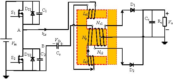
Fig. 3. Half-bridge LLC resonant converter based on magnetic integration.
The planar magnetic integrated transformer is applied to the half-bridge LLC series resonant converter. There are two resonant frequencies in the half-bridge LLC resonant converter, f and f. f is the resonant frequency of inductance L and capacitor C, and f is the frequency at which the sum of inductance L and excitation inductance L of the transformer resonates with the capacitor. In order to maximize efficiency, the working range of the frequency is set between f and f, and the current works in a discontinuous mode (DCM). In this case, not only ZVS of the switch can be turned on, but also the rectifier diode on the secondary side can be turned off at zero current. The main waveforms of the converter operating between f and f are shown in Figure 4.
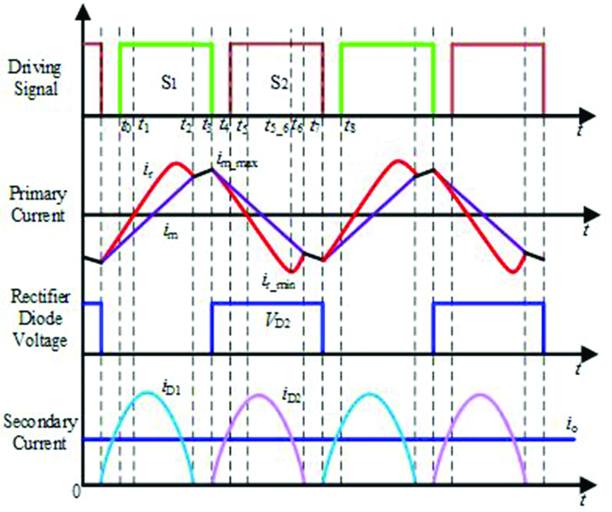
Fig. 4. Main waveforms of LLC when f f f.
B. Design and selection of integrated magnetic elements
Figure 5 shows the air gap and cross-section of the integrated magnetic elements; l is the length of the air gap of the planar transformer magnetic core. For the convenience of the design, the three cylinders of the EI core have the same air gap. S, S, and S represent the core cross-sectional area of two side columns and a central column of the planar transformer, respectively. Since EI magnetic core is selected, S = 2S = 2S.
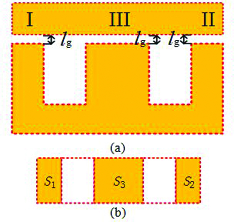
Fig. 5. Air gap and cross-section of planar integrated magnetic elements. (a) Air gap of EI core. (b) Cross-sectional area of magnetic core.
Formula (8) represents the magnetoresistance of each cylinder of the integrated magnetic element, where represents the air permeability
| (8) |
In order to analyze the magnetic density variation of the integrated magnetic element applied in the LLC resonant converter, we select the continuous phase in Figure 4 because the magnetic element of LLC resonant converter is bidirectionally excited and has periodicity. In t–t, the rectifier diode of the secondary side of the transformer is switched on, the voltage of the primary winding of the transformer is clamped to nV, and the voltage of the secondary winding is –V; so V can be expressed as
| (9) |
For the center leg III of the core, the magnetic flux of both sides of the cylinder will not pass through, and the magnetic flux density of the center column reaches the maximum value during t–t. According to formula (9), the maximum magnetic density B of the middle column is
| (10) |
When the half-bridge LLC converter operates in modes 3, 4, 5, and 6, there are
| (11) |
At t, the magnetic density of core side leg I reaches the maximum value, and because =+, the maximum magnetic density B is obtained as follows:
| (12) |
In the calculation, the voltage of the winding is equal to the DC voltage. In practical application, the voltage will change due to resonance and the actual flux density will be slightly less than the obtained flux density. Therefore, the coefficient k is introduced to obtain the real flux density, and the value of k is about 0.7–0.9.
For the maximum flux density B of the magnetic leg II, when the resonant current of the inductor reaches the maximum or minimum value, the flux density reaches the maximum value and the converter operates at t t t. The magnetic density began to increase at t. According to formula (12) and =+, B can be obtained as follows:
| (13) |
In the same way as formula (12), the voltage of the winding is equal to the DC voltage. Therefore, the coefficient k is introduced to obtain the real flux density of cylinder II, and the value of k is about 0.7–0.9.
Through the above formula, we can verify whether the selected magnetic core is reasonable. Because the magnetic flux cancelation effect will occur in cylinder III and cylinder II, the magnetic flux density of cylinder I and cylinder III will not be offset but will be superimposed. Therefore, it is only necessary to ensure that cylinder I is not saturated and the other two cylinders will not be saturated. In formula (11), t–t is about half of a cycle; so formula (11) can be simplified as follows:
| (14) |
In formula (14), f is the working frequency of half-bridge LLC resonant converter. In the calculation, the minimum value of working frequency should be selected.
For the selection of the magnetic core size under the determined power, first, select the type under the worst working conditions. According to formula (14), ensure that the maximum magnetic flux density will not saturate the magnetic core at this time, and the coefficient k in the formula has guaranteed the magnetic flux density margin.
IV. SIMULATION ANALYSIS OF PLANAR MAGNETIC INTEGRATION
A. Parameter setting
In the design, we make LLC resonant converter work between f and f, which can not only realize soft switching but also realize ZCS of secondary rectifier diode. According to the input voltage range, the working frequency range of LLC resonant converter is 125–180kHz. The main parameters of half-bridge LLC resonant converter are shown in Table 1.
The planar EI core is made of PC95 ferrite EI22/8/16. The structure of E core and I core is shown in Figure 6, and the specific core parameters are shown in Table 2.
Table 1: Main parameters of converter
| Specifications | Values |
| Resonant frequency | 200 kHz |
| Input voltage range | 60–80 V |
| Output voltage | 10 V |
| Power | 20 W |
| Turn ratio of transformer | 4:1 |
| Resonant inductor | 20 H |
| Excitation inductance | 56 H |
| Resonant capacitor | 33 nF |
For the method of setting air gap, we use 0.06-mm air gap gasket to ensure that the air gap of each cylinder is the same. According to formulas (6) and (7), the number of turns of the inductor on the side leg of the planar magnetic core is calculated as 4 turns, the number of original side turns of the transformer is 8 turns, and the number of secondary side turns of the transformer is 2 turns.
According to the formula deduced in Section III and the design parameters of LLC resonant converter, the maximum magnetic flux density is only 0.27T, while the saturated magnetic flux density of PC95 EI22/8/16 magnetic core is 0.55T, which verifies the rationality of the selected magnetic core.
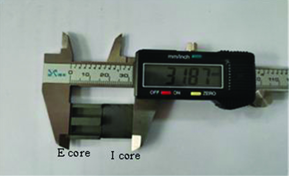
Fig. 6. Structure and size of E core and I core.
Table 2: Core parameters
| Cylinder | Area/mm | Air gap/mm | Reluctance/10H |
| I | 40 | 0.06 | 1.193 |
| II | 80 | 0.06 | 0.598 |
| III | 40 | 0.06 | 1.193 |
B. Simulation analysis
According to the design parameters of the planar magnetic integrated elements, the finite element analysis model of the magnetic integrated elements is established in Ansys Maxwell electromagnetic field simulation software. Considering the influence of simulation accuracy and computer performance, the mesh is divided based on the edge length of the inside element of the model, and the set length is 0.5 mm. According to a series of parameters of half-bridge LLC resonant converter design, an open-loop circuit is built in Maxwell circuit design and imported into Ansys Maxwell, the external circuit structure is shown in Figure 7. In the figure, Lwinding1 and Lwinding2 are the resonant inductance of the resonant cavity, Lwinding3 is the excitation inductance of the primary side of the transformer, and Lwinding4 and Lwinding5 are the excitation inductance of the secondary side of the transformer. This circuit is used as the external excitation source of the planar magnetic integrated model, and its parameters are set as input 60 V, switching frequency 125 kHz, and output rated load. After the simulation, observe whether the soft switching and zero current shutdown of the secondary side are realized and obtain the resonant current and driving waveforms of the down transistor and the current and voltage waveforms of the secondary rectifier tube. These waveforms are shown in Figures 8, and 9.
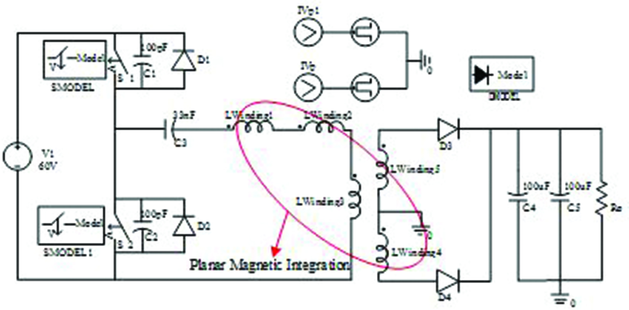
Fig. 7. External circuit structure diagram of simulation.
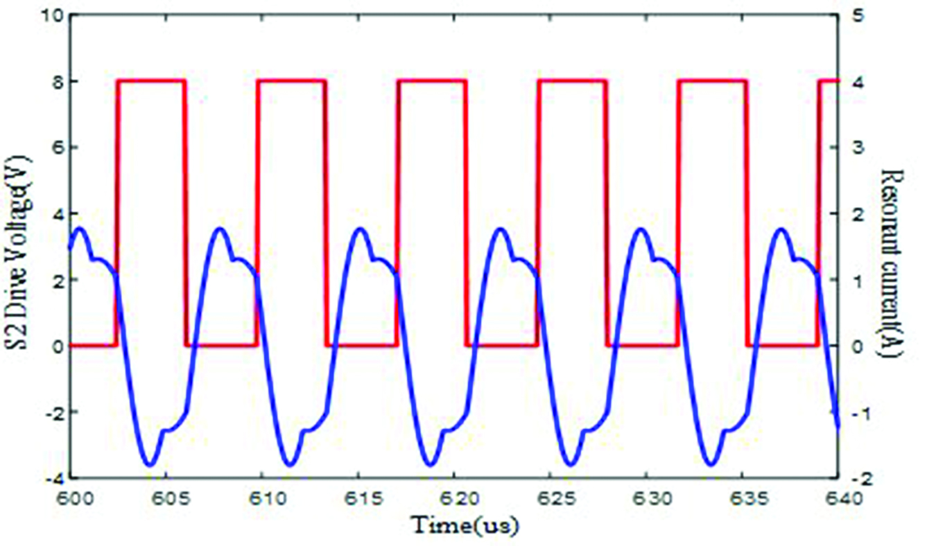
Fig. 8. Resonant current and S driving waveforms.
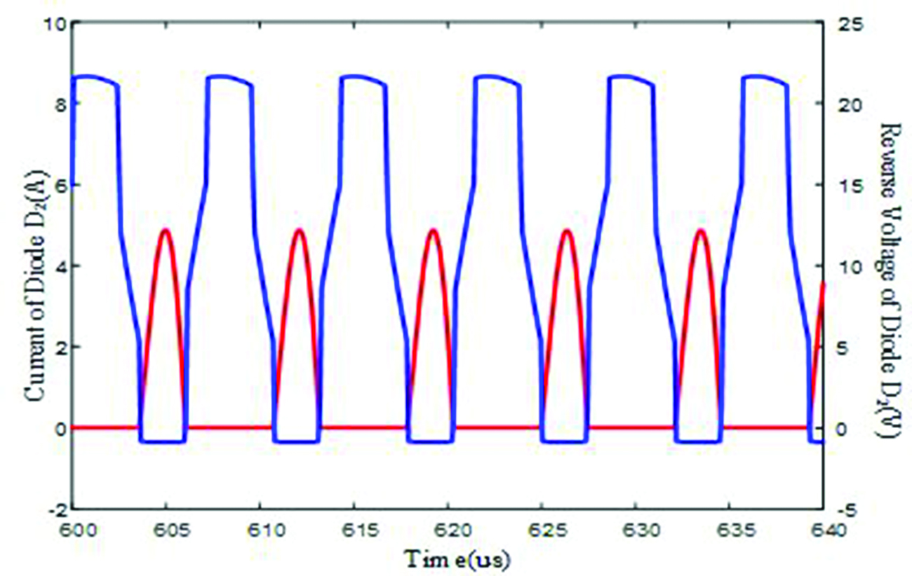
Fig. 9. Current and voltage waveforms of rectifier D.

Fig. 10. Magnetic flux density of planar magnetic integrated elements.
According to Figure 8, when S starts to turn on, the resonant current is positive. At this time, the body diode of S has conducted the freewheeling current, realizing ZVS of MOSFET. In Figure 9, when the current flowing through the rectifier diode is 0, the reverse voltage begins to increase. Therefore, the zero current shutdown of the rectifier diode is realized. In the figure, when the diode is on, it has a negative voltage because of the voltage drop. When analyzing the iron loss of the magnetic integrated structure, the parameters of PC95 material are imported into the software, and it is concluded that the core loss changes periodically. According to the calculation, the average core loss is about 0.41 W.
In the Ansys Maxwell-3D simulation environment, the model of planar magnetic integrated components is established, the external circuit is drawn, and the flux density distribution of planar magnetic integrated components is obtained by co-simulation. As shown in Figure 10, the maximum magnetic flux density of the magnetic integrated component is 0.285T, which is not different from the maximum magnetic flux density deduced from the formula. The rationality of the magnetic core selection is proved.
V. EXPERIMENTAL VERIFICATION
In order to verify the correctness and superiority of the structure design of planar magnetic integrated magnetic elements, an experimental prototype is built as shown in Figure 11.

Fig. 11. Testing system of LLC resonant converter.
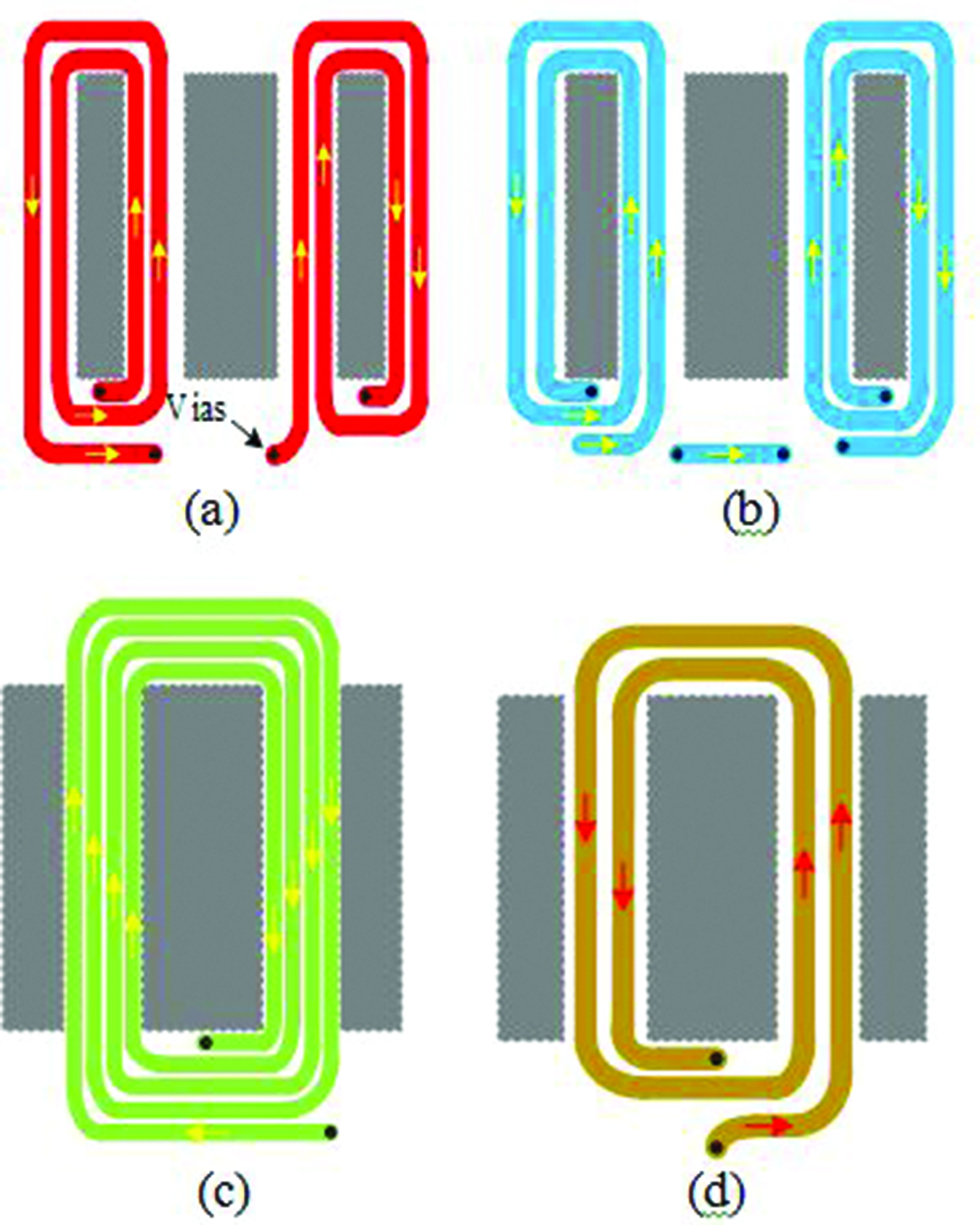
Fig. 12. Partial winding arrangement. (a) Layer 1. (b) Layer 2. (c) Layer 3. (d) Layer 4.
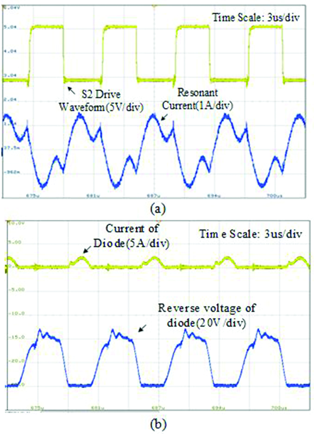
Fig. 13. Waveforms at 60-V input. (a) Resonant current and driving voltage waveforms. (b) Waveforms of diode current and reverse voltage.
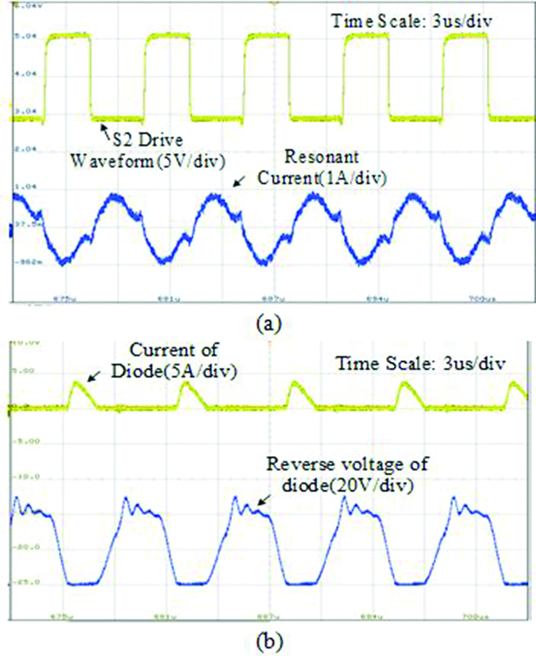
Fig. 14. Waveforms at 80-V input. (a) Resonant current and driving voltage waveforms. (b) Waveforms of diode current and reverse voltage.
Some winding configurations are shown in Figure 12, where (a) and (b) are the windings of the inductor, (c) is the primary winding of the transformer, and (d) is the secondary winding of the transformer. Each layer is connected through vias. The yellow arrow indicates the flow direction of the current in the primary winding and the red arrow indicates the flow direction of the current in the secondary winding.
When the input voltage is 60 V and the output voltage is 10 V, the resonant current and the waveform of switching tube S and the current and voltage waveforms of rectifier diode D are shown in Figure 13. When the input voltage is 80 V and the output voltage is 10 V, the current and voltage waveforms of rectifier diode D are shown in Figure 14.
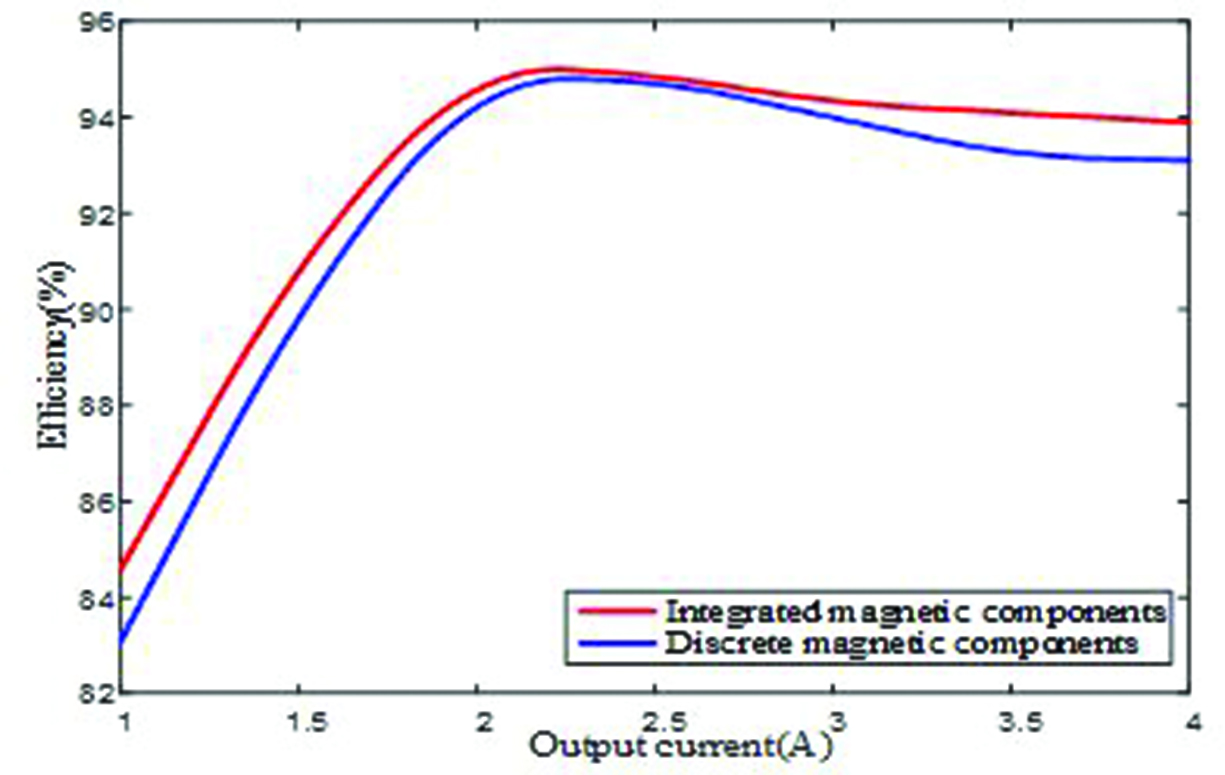
Fig. 15. Efficiency comparison curve.
According to Figures 13 and 14, when the driving voltage of the lower tube S increases, that is, when the lower tube is on, the resonant current is positive. At this time, the body diode of S has been turned on, realizing ZVS of the switching tube. When the current of rectifier diode is 0, the reverse voltage of the diode begins to increase, and ZCS of the secondary diode is realized. According to the oscilloscope, the working frequency is between 133 and 169 kHz, and the effective value of resonant current is 0.594–0.939A, which is basically consistent with the design parameters.
Table 3: Comparison of core size and mass
| Magnetic Parts | Core | Volume/mm | Quality/g | |
| Discreteness | Inductance | EE19 | 910 | 4.9 |
| Transformer | EE20 | 1450 | 7.6 | |
| Integration | EI22 | 2040 | 10.5 | |
In order to compare the integrated magnetic components with the discrete magnetic components, the geometric dimensions and parameters of each magnetic component are given in Table 3. The volume of the integrated magnetic component is 2040 mm and the mass is 10.5 g. Compared with the discrete magnetic elements, the volume and weight of the planar integrated magnetic elements are reduced by 13.56% and 16%, respectively. For the whole circuit board, the power density is increased by 15%.
Under the same conditions, the efficiency comparison curve of half-bridge LLC resonant transformer is obtained by testing the discrete magnetic devices and integrated devices, as shown in Figure 15. Compared with the traditional discrete magnetic components, the planar core has a larger body ratio and is more conducive to heat dissipation. Due to the magnetic flux cancelation effect, the core loss is reduced. When the output current is 2.2 A, the efficiency reaches the maximum in both cases. At this time, the corresponding efficiency of the discrete magnetic components is 94.2%, and the efficiency of the integrated magnetic components is 94.9%. Within full load range, the efficiency of planar integrated magnetic components is significantly higher than that of discrete magnetic components, and the efficiency curves have the same trend.
VI. CONCLUSION
In this paper, a planar magnetic integrated component based on independent inductance is proposed. The inductor and transformer are integrated on a planar magnetic core by the decoupling integration method and the inductor and transformer are decoupled completely. It is applied to half-bridge LLC resonant converter. It is proved that there is no coupling between the inductor and transformer by the formula derivation, and the design and selection methods of magnetic integrated components are proposed. The excitation inductance of the inductor and transformer can be easily controlled by changing the air gap and winding turns. In addition, the electromagnetic field characteristics of planar magnetic integrated components are analyzed in the simulation software. Finally, a 20-W 200-kHz half-bridge LLC resonant converter is built, which achieves good soft switching performance in the whole load range, and the peak efficiency reaches 94.9%.
ACKNOWLEDGMENT
This work was supported by the Natural Science Foundation of Jiangsu Province under Grant BK20190634 and Postgraduate Research & Practice Innovation Program of Jiangsu Province under Grant KYCX21_2226.
REFERENCES
[1] C. Fei, R. Gadelrab, Q. Li, and F. C. Lee, “High-frequency three-phase interleaved LLC resonant converter with GaN devices and integrated planar magnetics,” IEEE J. Emerg. Sel. Topics Power Electron., vol. 7, no 2, pp. 653-663, Jun. 2019.
[2] C. Fei, F. C. Lee, and Q. Li, “High-efficiency high-power-density LLC converter with an integrated planar matrix transformer for high-output current applications,” IEEE Trans Ind Electron., vol. 64, no. 11, pp. 9072-9082, Nov. 2017.
[3] R. X. Liu, Y. F. Wang, Q. Chen, F. Q. Han, and Z. Meng, “Entire magnetic integration method of multi-transformers and resonant inductors for cltlc resonant converter,” Electronics., vol. 9, no. 9, 1386, Sep. 2020.
[4] Z. W. Ouyang, O. C. Thomsen, and M. A. E. Andersen, “Optimal design and tradeoff analysis of planar transformer in high-power DC-DC converters,” IEEE Trans Ind Electron., vol. 59, no. 7, pp. 2800-2810, Jul. 2012.
[5] Y. C. Yang, M. K. Mu, Z. Y. Liu, F. C. Lee, and Q. Li, “Common mode EMI reduction technique for interleaved MHz critical mode PFC converter with coupled inductor,” IEEE Energy Convers. Congr. Expo., pp. 233-239, Sep. 2015.
[6] X. C. Huang, J. J. Feng, W. J. Du, F. C. Lee, and Q. Li, “Design consideration of MHz active clamp flyback converter with GaN devices for low power adapter application,” IEEE Appl. Power Electron. Conf., pp. 2334-2341, May. 2016.
[7] Y. C. Liu, C. Chen, K. D. Chen, Y. L. Syu, D. J. Lu, K. A. Kim, and H. J. Chiu, “Design and implementation of a planar transformer with fractional turns for high power density LLC resonant converters,” IEEE Trans Power Electron., vol. 36, no. 5, pp. 5191-5203, May 2021.
[8] K. W. Kim, Y. Jeong, J. S. Kim, and G. W. Moon, “Low common-mode noise full-bridge LLC resonant converter with balanced resonant tank,” IEEE Trans Power Electron., vol. 36, no. 4, pp. 4105-4115, Apr. 2021.
[9] J. Biela, and J. W. Kolar, “Electromagnetic integration of high power resonant circuits comprising high leakage inductance transformers,” IEEE Power Electron., pp. 4537-4545, Jun. 2004.
[10] M. X. Li, Z. W. Ouyang, and M. A. E. Andersen, “High-frequency LLC resonant converter with magnetic shunt integrated planar transformer,” IEEE Trans Power Electron., vol. 34, no. 3, pp. 2405-2415, Mar. 2019.
[11] J. Zhang, Z. W. Ouyang, M. C. Duffy, M. A. E. Andersen, and W. G. Hurley, “Leakage inductance calculation for planar transformers with a magnetic shunt,” IEEE Trans Ind Appl., vol. 50, no. 6, pp. 4107-4112, Dec. 2014.
[12] S. S. Gao, Y. J. Wang, Y. S. Guan, and D. G. Xu, “A high step up SEPIC-based converter based on partly interleaved transformer,” IEEE Trans Ind Electron., vol. 67, no. 2, pp. 1455-1465, Feb. 2020.
[13] L. X. Xue, M. K. Mu, D. Boroyevich, and P. Mattavelli, “The optimal design of GaN-based dual active bridge for bi-directional plug-in hybrid electric vehicle (PHEV) charger,” IEEE Appl. Power Electron. Conf., pp. 602-608, Mar. 2015.
[14] L. Wu, L. Xiao, J. Zhao, and G. Z. Chen, “Modelling and optimisation of planar matrix transformer for high frequency regulated LLC converter,” IET Power Electron., vol. 13, no. 3, pp. 516-524, Feb. 2020.
[15] M. H. Ahmed, F. C. Lee, and Q. Li, “Wide voltage range high-efficiency sigma converter 48V VRM with integrated magnetics,” IEEE Ener Conv., pp. 4701-4707, Oct. 2019.
[16] S. Q. Li, Q. Y. Min, E. G. Rong, R. Zhang, X. Du, and S. Z. Lu, “A magnetic integration half-turn planar transformer and its analysis for LLC resonant DC-DC converters,” IEEE Access., pp. 128408-128418, Sep. 2019.
[17] Y. Jin, W. Xie, N. Yang, and H. Y. Liu, “High efficiency resonant DC/DC converter based on GaN Device and planar transformer,” IEEE 5th Information Technology and Mechatronics Engineering Conference., pp. 358-362, Jun. 2020.
[18] F. C. Lee, Q. Li, and A. Nabinh, “High frequency resonant converters: an overview on the magnetic design and control methods,” IEEE J. Emerg. Sel Topics Power Electron., vol. 9, no. 1, pp. 11-23, Feb. 2021.
[19] M. C. Dai, X. J. Zhang, H. Li, D. B. Zhou, Y. J. Wang, and D. G. Xu, “LLC converter with an integrated planar matrix transformer based on variable width winding,” Intermationl Conference on Electrical Machines and System., pp. 229-232, Aug. 2019.
BIOGRAPHIES

Xianming Deng was born in Sichuan, China. He received the B.S., M.S., and Ph.D. degrees in electrical engineering from the China University of Mining and Technology, Jiangsu, China.
He is currently a Professor with the School of Electrical and Power Engineering, China University of Mining and Technology. His current research fields include power electronics and motor drive.

Kang Zheng received the B.S. degree in electrical engineering from the China University of Mining and Technology, Xuzhou, China, in 2019, where he is currently working toward the M.S. degree with the School of Electrical and Power Engineering.
His current research interests include high frequency transformer and DC/DC converters.

Yanxing Gu received the B.S. degree in electrical engineering from the Xu Zhou University of Technology, Xuzhou, China, in 2019. She is currently working toward the M.S. degree with the China University of Mining and Technology.
Her current research direction is in motor design.

Ankang Zhang was born in Jiangsu, China. He received the B.S. degree in electrical engineering and intelligent control from Nantong University, Jiangsu, China. He is currently working toward the master’s degree with the China University of Mining and Technology.
His current research interests include motor control and transformer design.

Zhen Jia was born in Xinjiang, China. He received the B.S. degree in electrical engineering from Chongqing University, Chongqing, China. He is currently working toward the master’s degree with the China University of Mining and Technology.
His current research interests include power electronics and motor drive.
ACES JOURNAL, Vol. 36, No. 11, 1474–1483.
doi: 10.13052/2021.ACES.J.361112
© 2021 River Publishers