Design and Analysis of a Novel Linear Oscillating Actuator with Dual Stator Rectangular Geometry
Muhammad Jawad, Yu Haitao, Zahoor Ahmad, and Yulei Liu
School of Electrical Engineering, Southeast University Nanjing 210096, China
engrjawad@seu.edu.cn, htyu@seu.edu.cn, engrzahoor@seu.edu.cn, liuyulei@seu.ed.cn
Submitted On: April 9, 2021; Accepted On: September 26, 2021
Abstract
This paper proposes a new design of a linear oscillating actuator (LOA) with rectangular topology of stator and mover. The shape of a permanent magnet (PM) has a major impact on cost, mechanical strength, and generation of magnetic flux density. This design uses rectangular PMs that are relatively cheaper than tubular PMs. Proposed LOA operates on single phase AC loading source. All the design parameters are optimized by using parametric sweep and the response of the LOA in terms of thrust force is compared. The electromagnetic (EM) force received by the mover is investigated at various mover positions as well as at different values of the current. Motor constant is examined toward both directions of the force. Resonance phenomena is analyzed using input and output power of the LOA, which is the unique advantage of the LOA. Compared to the conventional LOA designs, the output parameters of the LOA, such as EM force, stroke, operating frequency and power, show great improvement with regards of volume of the proposed LOA. This topology shows significant development in terms of thrust force, motor constant, easy manufacturing and cost. Moreover, range of the stroke of proposed LOA is feasible for linear refrigeration system.
Index Terms: FEM, linear oscillating actuator, moving magnet, rectangular topology, resonance.
I. INTRODUCTION
Linear oscillating actuators (LOAs) provide linear oscillatory thrust force directly without using special mechanism (crank shaft) for converting rotary motion to linear oscillations [1]. Compared to conventional mechanism where rotary motion is converted to linear oscillation, mover of the LOA is directly attached to the piston and resonant springs. On the basis of simple structure, high power density and high efficiency, LOA received extensively more attention in industrial applications, such as compressor, vehicle suspension system, and bio-medical equipment [2, 3].
There are three types of LOA configurations of conventional topologies of LOA: moving magnet, moving coil, and moving iron. Moving magnet configuration is generally composed of coil housed in the stator and mover has permanent magnets (PMs) [4]. Moving coil LOA is comprised of coils placed on both stator and mover [5]. Moving iron LOA has winding coils on the stator and mover is only composed of iron of different shapes. The performance of moving magnet type LOA is lot better in contrast to the other type of LOAs on the count of high thrust density, high efficiency, smaller mover mass, and easy manufacturability [6, 7].
Tubular topology has squeezed structure and produces high flux density but the lamination of the core materials is very challenging. The core part of classical rotational equipment is laminated radially for the reduction of core loses. However, due to limitation of low flux density and small stacking factor, a new technique of axial lamination is analyzed in [8]. This investigation improves stacking factor that further improves amount of flux density in the air gap of LOA. Furthermore, back emf and thrust force of the LOA are also enhanced by using this new methodology. In contrast to this approaches, rectangular topology of LOA is more feasible for laminations. Conventionally, a rectangular topology is analyzed in [9, 10] where an E core stator is used and four PMs with opposite polarities are placed on the mover. This topology is simple and easy to fabricate. Moreover, PM used in rectangular LOA is also of rectangular shape and shape of the PM has significant effect on cost and housing on the mover. Reduction of iron loses is studied in [11], where a special formation of grove in the inner yoke is analyzed. Furthermore, the effect of number of groves is also examined.
There are two additional significances of LOA over conventional actuation mechanism: oscillations with adjustable stroke and operation at resonance frequency. Stroke of the LOA can be adjusted by input loading to the LOA. By increasing input power to the LOA, stroke of LOA increases, enhancing the cooling capacity of the refrigeration system [12]. Main limitation of high-input power is more copper loses due to which efficiency of system reduces [13]. Resonance at LOA is achieved by exciting it with frequency equal to mechanical resonance frequency of the system. Mechanical resonance frequency is calculated by using the value of mover mass and spring stiffness [14]. At resonance condition, least amount of current is required for feasible operation of the LOA that improves the efficiency of the LOA [15, 16].
Moving magnet LOA with capability of self-holding is studied in [17]. This paper analyzed the effect of slot opening and magnetic circuit on thrust force and self-holding force. An E-core and C-core LOAs with different configurations of PMs placed on mover is analyzed and compared in [18]. A new topology of ferrite PM LOA is compared with conventional rare earth PM LOA in [19]. In this study, all the output parameters of LOA are investigated using ferrite PM, that indicates promising improvement. Another moving magnet machine is studied that provides both rotary and linear motion. This design uses rotary and linear arrangement of coils connected axially and circumferentially [20, 21].
This paper describes a detailed analysis of moving magnet, rectangular-shaped LOA for compressor in refrigeration system. Design topology and operating principle of the investigated LOA is explained. To show proposed topology in real view, CAD model is used. All the design parameters are optimized using parametric sweep tool. Output parameters like thrust force and stroke are analyzed and compared. Resonance phenomena are discussed by using design parameters, spring stiffness, and mover mass. Furthermore, all the output parameters are compared with conventional design of LOA.
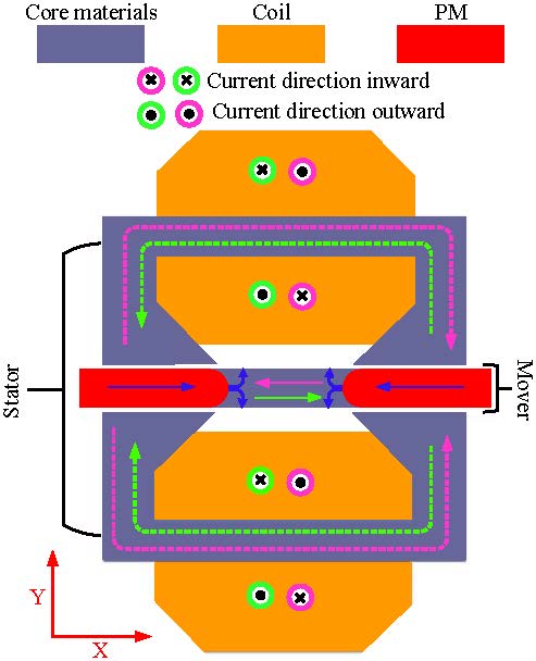
Fig. 1. 2-D topology of proposed LOA.
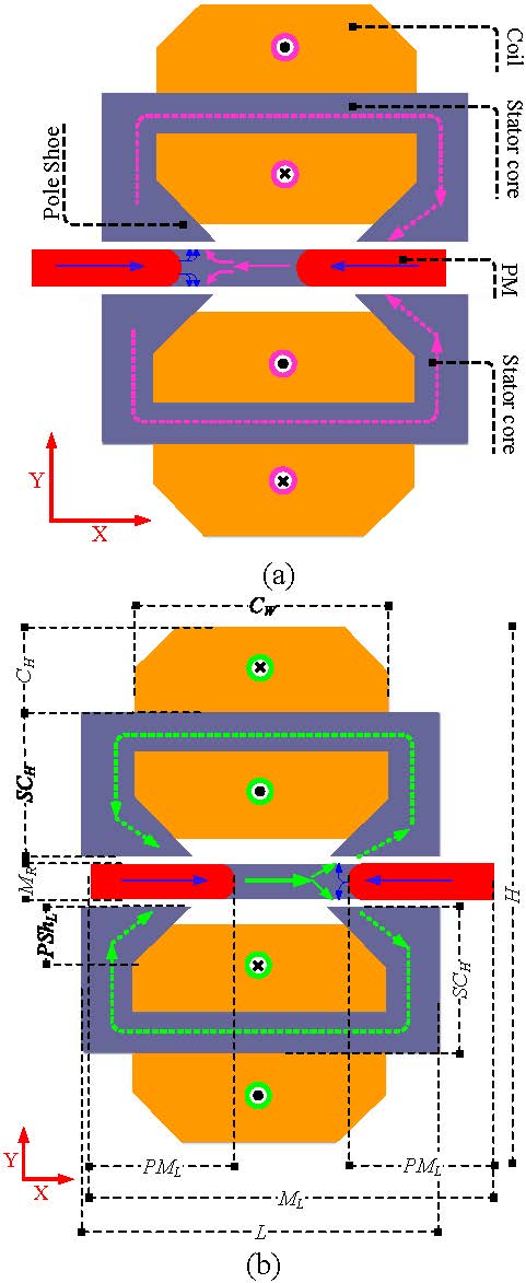
Fig. 2. Proposed LOAs: (a) extreme position of the mover, (b) extreme position of the mover.
II. DESIGN AND OPERATING PRINCIPLES
Mechanical structure of proposed LOA is composed of two main parts, two C-shaped rectangular stator cores and mover, as shown in Figure 1. Stators, stationary parts of the LOA, are further composed of core material and windings. Concentrated type winding is convoluted through back side of C-shaped stator core. Pole shoes, the end of two sides of the C-shaped core, are expanded to provide ease to the magnetic flux as magnetic flux lines rebound back through sharp edges of the core. Direction of the current through upper and lower stator coils is opposite for that it is wound in opposite directions. When the coils are excited by single phase AC, magnetic flux lines are started at one stator leg and end at the corresponding other stator leg.
Table 1: Dimensions of design parameters of the LOA
| Description | Symbol | Value (mm) |
| Length of LOA | L | 80 |
| Height of LOA | H | 116 |
| Depth of LOA | D | 100 |
| Mover radius | M | 5 |
| Mover Length | M | 90 |
| Stator core height | SC | 33 |
| Pole shoe length | PSH | 13 |
| Coil height | C | 20 |
| Coil width | C | 56 |
| PM length | PM | 32 |
| Air gap | A | 1 |
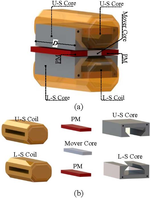
Fig. 3. 3-D topology of investigated LOA: (a) Complete view, (b) Open parts view.
Mover, moving part of LOA, is comprised of mover core and PMs. Two axially magnetized, rectangular-shaped PMs are housed at both ends of the mover. PMs’ magnetization direction is opposite and toward the centered mover core. Mover core is placed between two PMs and poses a least reluctance rout for magnetic flux originated from one stator pole and ending at the other stator pole. The faces of the PMs toward the mover core are made fillet to generate flux lines in diverging mode. Additionally, fillet PMs help the mover to interact easily with stator poles.
Operating principles: when the coils of both the stators are energized in opposite directions, magnetic flux density is produced in opposite directions. Magnetic flux density produced by one stator leg links with mover core and then enters to the corresponding opposite pole of the same stator. Magnetic flux density of both coils and PM tends to enters into the corresponding other stator legs. According to the basic principles of magnetic field alignment phenomena, magnetic field lines strive to pass through least reluctance path. To provide least reluctance path, mover adjusts its position. Moreover, mover experiences an electromagnetic (EM) force in one direction. Since proposed LOA is operating on single phase AC so for a positive cycle of an AC, mover experiences EM force in one direction. Figure 2 (a) shows extreme position of the mover. Direction of the current and rout followed by magnetic flux density is depicted by symbols and arrows, respectively. During remaining negative cycle of an AC, direction of electric current becomes opposite. Hence, the direction of magnetic flux density through stator poles becomes altered. At this time, mover receives EM force in the opposite direction, as shown in Figure 2 (b). In Figure 2 (b), mover is displaced to extreme position of the oscillations, as shown. Mover will receive a reciprocating EM when the coil is loaded by single phase alternating electric power. CAD model of proposed LOA is shown in Figure 3. Table 1 shows the dimensions of different parameters of investigated LOA.
III. PARAMETRIC ANALYSIS
Parametric analysis of different parameters of the LOA is made by adopting parametric analysis technique and selecting the best magnitude of the investigated design parameter. Effect of different parameters like pole area and air gap is studied [23]. Effect of mover core length on thrust force, mover mass and operating resonance frequency is depicted in Figure 4. In this procedure, length of the PM is kept constant while mover core length is varied, due to which the overall length of the mover is also changed. EM force is verified for both directions of the current of value 5 A, as shown by red lines. Since, by increasing mover length, mover mass is also increased which further effects the value of operating resonance frequency. Blue and pink lines show effect of mover core length on mover mass and operating resonance frequency for spring stiffness of 50 KN⁄m, respectively. Optimum points are shown by dotted black squares. Figure 4 concludes that optimum value of mover core length is 26 mm. Additionally, at optimum value of mover core length, value of operating resonance frequency and mover mass are 50 Hz and 0.51 kg, respectively.
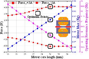
Fig. 4. Mover length optimization.
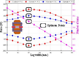
Fig. 5. Stator pole width optimization.
Furthermore, another parameter of LOA known as stator leg width is optimized and response is recorded in terms of EM force, as shown in Figure 5. During this procedure, position of the mover is fixed at mean position: from where the mover can move 6 mm back and forward. Other parameters of LOA like LOA height and length are kept constant. Stator leg width is varied toward the coil slot. Number of turns of coil is also kept changing. This process is repeated for 5 A, 3 A, –5 A, and –3 A shown by solid and dotted red and blue lines in Figure 5. This process concludes that optimum value of stator leg width is 12 mm at which the number turns of coil is 800.
IV. RESULTS AND DISCUSSIONS
Investigated LOA is simulated and its view is shown in Figure 6 where mover is displaced to extreme positions of oscillations. Current applied to the coil is 5 A DC with suitable arrangement of the current direction. Figure 6 (a) represents extreme position of the mover and rout followed by magnetic field line is shown by an arrow. At this arrangement of the coil current direction, mover experiences EM force toward direction. By altering the direction of the coils current, magnetic flux density direction becomes reverse, as shown in Figure 6 (b). At this route of current, direction of EM force becomes reverse and mover experiences EM force toward direction. Hence by applying single phase AC, mover will experience an oscillatory EM force. Legend to the right of simulated view of the LOA shows magnitude of magnetic flux density at different portions of the LOA.

Fig. 6. Magnetic flux distribution view after simulating the proposed LOA. (a) EM force toward direction, (b)EM force toward direction.
Magnetic flux density received by stator poles using 5 A DC is depicted in Figure 7. In this procedure, magnetic flux density is measured in the mid of air gap through a line in front of stator poles. Doted red and solid black lines show magnitude of magnetic flux density received by right, upper, and lower stator poles, respectively. Similarly, doted blue and solid pink lines show magnetic flux density received by left, upper, and lower stator poles, respectively.
Electromagnetic force response of proposed LOA for distinct magnitudes of the direct current is shown in Figure 8. This figure shows bi-directional EM force of the LOA for both direction of the DC. From the figure it is clear that there is linear relation between current and EM force. Current exceeding from 5 A value of the DC, there is some decrease in EM force per change in current due to saturation of the core materials. Motor constant (MC): EM force per Ampere current of the proposed LOA is 120 N/A. Proposed LOA shows identical MC toward both directions of the EM force.
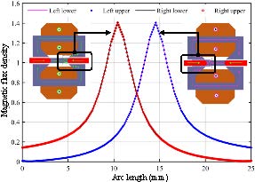
Fig. 7. Magnetic flux density linking with stator.
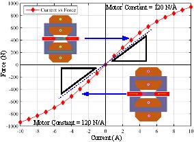
Fig. 8. EM force for different values of the DC.
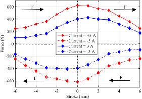
Fig. 9. EM force on different positions of the stroke.
EM force response of proposed LOA at different positions of the mover is presented in Figure 9. For proper explanation, every quarter of the figure is described separately. EM force shown in second quadrant displaces the mover from negative extreme position to the mean position of the oscillations. Mover will be further displaced to the positive extreme position by EM force shown by first quadrant of the Figure 9. By changing the direction of the current, direction of EM force becomes opposite as shown in third and fourth quadrants. EM force shown in third and fourth quadrants assists the mover to move from positive extreme position to the mean position and furthermore to the negative extreme position.
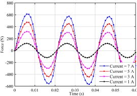
Fig. 10. Time-dependent EM force response.
Figure 10 shows EM force produced by proposed LOA for different peak to peak values of an AC at mean position of the mover. Positive value of the force indicates that force is toward axis and negative value of the force shows that the force is toward axis. From Figure 10, it is also clear that by increasing peak to peak value of single-phase supply, EM force is increased equally to both sides. This analysis concludes that on sinusoidal input loading, force experienced by mover is sinusoidal.
V. RESONANCE
A. Mechanical resonance
By comparison with conventional reciprocating compressor, LOA is normally operating under resonance condition that enhances the operational results of the LOA to a great extent. For proper operation of the LOA, minimum input current is needed at resonance condition that further leads to high efficiency of the system. Output results of the LOA in response to the input current, like stroke to electromagnetic force fraction and stroke to current relation of the LOA are high at resonance conditions [12]. Resonance frequency is calculated on the basis of mover mass and stiffness of the springs installed. Mover mass is a design parameter of the LOA and cannot be reduced to a great extent. However, mover mass can be optimized to some range keeping other parameters, like EM force and stroke of the LOA at optimum value. Resonance condition of LOA is achieved by exciting the coils at resonance frequency. Relationship for determining the mechanical resonance frequency is
| (1) |
where is the mechanical resonance frequency in Hz, is the spring stiffness, and is the mass of the mover. Value of spring stiffness selected in this analysis is 50 . The general demonstration of mass spring system of the LOA is depicted in Figure 11. Mechanical springs release and absorb energy to and from the system when it is required.
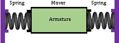
Fig. 11. Mechanical model of proposed LOA.
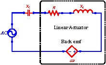
Fig. 12. Electrical circuit model of proposed LOA.
B. Electrical resonance
General representation of electrical system of the LOA is shown in Figure 12. In this figure, R is the resistance of actuator windings, is the coil inductance, is the required capacitance to get electrical resonance and is the back emf constant. At electrical resonance, inductive reactance of the coil is canceled out by capacitive reactance of capacitor. For producing capacitive reactance, an external capacitor is used. At electrical resonance condition, electrical system of the LOA act as a resistive load. Due to electrical resonance, LOA offers minimum impedance that improves the efficiency of the system. Relationship for finding necessary capacitance to produce electrical resonance in LOA is
| (2) |
where is the value of necessary capacitance to produce electrical resonance, is the operative frequency of alternating loading, and is the coil inductance.
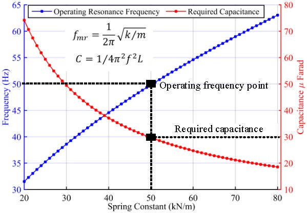
Fig. 13. Relation between spring constant, operating resonance frequency, and required capacitance.
C. Simulation results of resonance analysis
As deliberated in earlier section, mechanical resonance frequency of LOA is calculated by using Equation (1). Additionally, on the basis of operating frequency, external capacitance required for creating electrical is determined by using Equation (2). Figure 13 shows the relation of spring constant with resonance frequency which further influences value of external capacitance attached in series. During this analysis, value of mover mass is 0.51 kg. Figure 13 reveals that for spring constant of value 50 , operating resonance frequency of proposed LOA is . Furthermore, necessary capacitance to create electrical resonance is 30 μF.
At resonance, due to minimum variance between applied voltage and back emf, minimum amount of current is passed through LOA that further provides minimum electromagnetic force [22]. Current and electromagnetic force relation derived in [12] are used to calculate influence of operating frequency on input current and electromagnetic force. Figure 14 shows the values of input current and electromagnetic force for different values of operational frequency. Since mechanical resonance frequency of proposed LOA is 50 Hz, there is only a minimum current that passes through LOA which further yields minimum electromagnetic force.
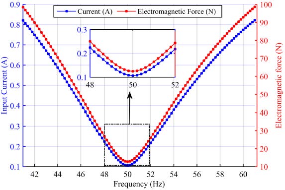
Fig. 14. Influence of operating frequency on input current and electromagnetic force.
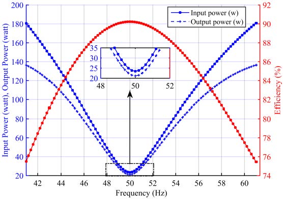
Fig. 15. Efficiency at various frequencies of the proposed LOA.
LOA input power is calculated by multiplying voltage across the coils and current flowing through the coils. Similarly, output power is determined by using the product of electromagnetic force and velocity of the mover. Mathematical formulas for current, electromagnetic force, and velocity are used which is derived in [12]. Figure 15 shows effect of operating frequency on output power, input power which further effects on efficiency of the LOA. Figure 15 reveals that on resonance frequency, proposed LOA operates at maximum efficiency. Shifting from the value of resonance frequency in either direction, difference between input power and output power increases and due to that efficiency reduces. At resonance frequency, proposed LOA gives maximum efficiency.
VI. COMPARISON WITH CONVENTIONAL DESIGNS OF LOAS
Performance parameters like volume, stroke, moving mass, MC, and efficiency comparison are shown in Table 2. This section overviews the design and performance comparison of investigated LOA with currently designed topologies of LOA for compressor application. Topology explored in [19] is moving magnet LOA where rare earth PM is replaced by ferrite PMs. PMs used in this topology of LOA is radially magnetized. Fabrication of such topology is complex and degrades the mechanical strength of mover structure. Moving magnet actuator investigated in [4] comprised of axially magnetized disk-shaped PMs. This topology is low cost and easy to fabricate. The main limitation of topology used in [4] is high mover mass (MM) due to which the value of operating resonance frequency is low. Another design analyzed in [6] is moving iron with coil housed on the stator. This topology has no PMs due to which the design cost is very low; however, MC of this design is very small. LOA topology investigated in [12] is E-core stator and mover composed of radially magnetized PM. Main complication of this topology is complex mover structure due to radially magnetized PMs housed. Performance behavior of this design is fair and feasible for refrigeration application.
Table 2: Parameters comparison of the investigated LOA with currently designed actuators
| Spec…. | Ref. | Ref. | Ref. | Ref. | Prop. |
| [19] | [4] | [6] | [12] | LOA | |
| Moving Type | PM | PM | Iron | PM | PM |
| Volume | 9.3 | ||||
| Stroke (mm) | 15 | 14 | 23 | 8.8 | 12 |
| Moving Mass (Kg) | 0.27 | 1 | 0.62 | 0.68 | 0.51 |
| MC (N/A) | 115 | 34.6 | 14 | 38 | 120 |
| Efficiency (%) | —— | 89 | 87 | 94 | 90 |
Design topology of proposed LOA is simple and easy to manufacture compared to the conventional topologies of LOA. Structure of the PMs used in this topology is low cost and easy to arrange multiple PMs and to get desired dimensions. Winding of coil is open to the air, on account of that, cooling arrangement and replacing are feasible. Moreover, lamination of the core part of the proposed LOA is very simple and easy to assemble.
VII. CONCLUSION
This article investigates and analyzes a novel design of rectangular structured moving magnet LOA for compressor in refrigeration system. Rectangular-shaped axially magnetized PMs are housed on the mover. Structure and operating principle are explained in detail. For better understanding, CAD model is designed. All the parameters are optimized on the basis of EM force and mover mass. Output results, like EM force and stroke amplitude are analyzed. Time-dependent EM force is examined for different peak to peak time-dependent input loading. Resonance phenomena are described and the influence of resonance frequency on input current, EM force, and efficiency are investigated. Finally, performance and design parameters of proposed and already designed LOAs are compared. Performance results of proposed LOA show significant outcomes while having simple structure and low cost. Moreover, fabrication complication in proposed LOA is minimum compared to conventional LOAs. Lamination of core materials is the most problematic part in tubular topology which is resolved. Proposed LOA is easy to laminate their core part. Hence it can be concluded that, proposed rectangular LOA is the best alternative of conventional tubular topologies of LOA.
REFERENCES
[1] K. H. Kim, S. M. Jang, J. H. Ahn, J. Y. Choi, and S. S. Jeong, “Design and characteristics analysis of linear oscillatory actuator with ferrite permanent magnet for refrigerator compressor,” [J]. Journal of Applied Physics, vol. 117, no. 17, pp. 17C120, May. 2015.
[2] S. J. Wang, Z. D. Weng, and B. Jin, “Multi-objective Optimization of Linear Proportional Solenoid Actuator,” In 2020 International Applied Computational Electromagnetics Society Symposium (ACES) IEEE, pp. 1-2, Jul. 2020.
[3] I. I. Abdalla, T. B. Ibrahim, and N. M. Nor, “A study on different topologies of the tubular linear permanent magnet motor designed for linear reciprocating compressor applications,” Applied Computational Electromagnetics Society (ACES) Journal, vol. 31, no. 1, pp. 85-91, Jan. 2016.
[4] Z. Ahmad, A. Hassan, F. Khan, I. Lazoglu, “Design of a high thrust density moving magnet linear actuator with magnetic flux bridge,” IET Electric Power Applications, vol. 14, no. 7, pp. 1256-1262, Mar. 2020.
[5] H. Kim, M. Yoon and J. Hong, “Design and performance analysis of moving-coil type linear actuator,” 2011 International Conference on Electrical Machines and Systems, Beijing, China, pp. 1-4, Aug. 2011.
[6] A. Bijanzad, A. Hassan, and I. Lazoglu, “Analysis of solenoid based linear compressor for household refrigerator,” International Journal of Refrigeration, vol. 74, pp. 116-128, Feb. 2017.
[7] N. Ahmad, F. Khan, N. Ullah, and M. Z. Ahmad, “Performance analysis of outer rotor wound field flux switching machine for direct drive application,” Applied Computational Electromagnetics Society (ACES) Journal, vol. 33, no. 8, pp. 913-922, Aug. 2018.
[8] K. H. Kim, H. I. Park, S. S. Jeong, S. M. Jang, and J. Y. Choi, “Comparison of characteristics of permanent-magnet linear oscillating actuator according to laminated method of stator core,” IEEE Transactions on Applied Superconductivity, vol. 26, no. 4, pp. 1-4, June 2016.
[9] Y. Asai, K. Hirata, and T. Ota, “Amplitude control method of linear resonant actuator by load estimation from the back-EMF,” IEEE Transactions on Magnetics, vol. 49, no. 5, pp. 2253-2256, May 2013.
[10] Y. Asai, T. Ota, T. Yamamoto, and K. Hirata, “Proposed of novel linear oscillating actuator’s structure using topology optimization,” IEEE Transactions on Magnetics, vol. 53, no. 6, pp. 1-4, June 2017.
[11] J. Dai, Z. Zhao, S. Xu, C. Wang, J. Zhu, and X. Fan, “Inhibition of iron loss of the inner yoke in electromagnetic linear actuator,” IET Electric Power Applications, vol. 13, no. 4, pp. 419-425, Jan. 2019.
[12] A. Hassan, A. Bijanzad, and I. Lazoglu, “Dynamic analysis of a novel moving magnet linear actuator,” IEEE Transactions on Industrial Electronics, vol. 64, no. 5, pp. 3758-3766, May 2017.
[13] Z. Zhu, K. Liang, Z. Li, H. Jiang, and Z. Meng, “Thermal-economic-environmental analysis on household refrigerator using a variable displacement compressor and low-GWP refrigerants,” International Journal of Refrigeration, vol. 123, pp. 189-197, Mar. 2021.
[14] S. Khalid, F. Khan, Z. Ahmad, and B. Ullah, “Design and finite element analysis of modular C-Core stator tubular linear oscillating actuator for miniature compressor,” World Journal of Engineering, 2021. https://doi.org/10.1108/WJE-03-2021-0142.
[15] A. Bijanzad, A. Hassan, I. Lazoglu, and H. Kerpicci, “Development of a new moving magnet linear compressor Part B: Design and modeling,” International Journal of Refrigeration, vol. 113, pp. 70-79, May 2020.
[16] A. Hassan, A. Bijanzad, and I. Lazoglu, “Electromechanical modeling of a novel moving magnet linear oscillating actuator,” Journal of Mechanical Science and Technology, vol. 32, no. 9, pp. 4423-4431, Sep. 2018.
[17] P. Immonen, V. Ruuskanen, and J. Pyrhönen, “Moving magnet linear actuator with self-holding functionality,” IET Electrical Systems in Transportation, vol. 8, no. 3, pp. 182-187, Feb. 2018.
[18] X. Chen, Z. Q. Zhu, D. Howe and J. S. Dai, “Comparative study of alternative permanent magnet linear oscillating actuators,” 2008 International Conference on Electrical Machines and Systems, Wuhan, China, IEEE, pp. 2826-2831, Oct. 2008.
[19] C. W. Kim, G. H. Jang, S. W. Seo, I. J. Yoon, S. H. Lee, S. S. Jeong, and J. Y. Choi, “Comparison of electromagnetic and dynamic characteristics of linear oscillating actuators with rare-earth and ferrite magnets,” IEEE Transactions on Magnetics, vol. 55, no. 7, pp. 1-4, Jan. 2019.
[20] S. Mirić, M. Schuck, A. Tüysüz and J. W. Kolar, “Double stator linear-rotary actuator with a single set of mover magnets,” 2018 IEEE Energy Conversion Congress and Exposition (ECCE), pp. 750-757, Sep. 2018
[21] H. Feng, J. Si, Z. Cheng, C. Gao, and W. Cao, “Rotary coupling magnetic field characteristics of a two-degree-of-freedom direct drive induction motor,” Applied Computational Electromagnetics Society (ACES) Journal, vol. 34, no. 11, 2019.
[22] Z. Ahmad, A. Hassan, F. Khan, N. Ahmad, B. Khan and J. -S. Ro, “Analysis and design of a novel outer mover moving magnet linear oscillating actuator for a refrigeration system,” IEEE Access, vol. 9, pp. 121240-121252, Aug. 2021.
[23] R. Trentini, D. dos Santos, O. H. Reichow, and R. Piontkewicz, “Dynamic modeling and parametric analysis of the magnetic stiffness on a radial heteropolar rotor magnetic bearing (RMB),” International Journal of Electrical and Computer Engineering Research, vol. 1, no. 1, pp. 9-14, 2021.
BIOGRAPHIES

Muhammad Jawad was born in Pakistan in 1993. He received his B.S. degree in electrical engineering from University of Science and Technology, Bannu, KP, Pakistan in 2016. He got his M.S. degree from Southeast Univeristy in 2021. Currently, he is doing PhD degree in Southeast University, Nanjing, Jiangsu, China. His research interest is linear motor.

Haitao Yu PhD, professor, doctoral Supervisor. He received his PhD from Huazhong University of Science and Technology (HUST) in 1995. In 1997, he served as an associate professor in the School of Electric Engineering, HUST. During 1998–2003, academic exchange visits to Duke University and Canada. He served as editor of “Ocean Power Generation” special issue of Advances in Mechanical Engineering (SCI), and reviewer of various IEEE journals.

Zahoor Ahmad was born in KPK, Pakistan in 1993. He received BS degree in Electrical Engineering from University of Science and Technology, Bannu, KP, Pakistan in 2016 and MS degree in Electrical Engineering from COMSATS University Islamabad, Abbottabad Campus, Pakistan. He worked on research exchange program in GIK Institute for one plus year in Electrical Machine and Drive Lab. He is currently studying PhD in Electrical Engineering at Southeast University, Nanjing, Jiangsu, China. His research area is design of permanent magnet motors, linear oscillating actuator, and flux switching helical motors.

Yulei Liu was born in Jurong, Jiangsu, China in 1992. He received the B.S. degree in electric engineering from China University of mining and technology, in 2014 and M.S. degree in electric engineering from South China University of Technology, in 2018. He is currently pursuing the Ph.D. degree in electric engineering at Southeast University, Nanjing, Jiangsu, China. His research interests include permanent magnet motor, linear motor, magnetic gear motor, and magnetic lead screw.
ACES JOURNAL, Vol. 36, No. 10, 1384–1392.
doi: 10.13052/2021.ACES.J.361015
© 2021 River Publishers