A Gain-enhanced Dual-band Microstrip Antenna using Metasurface as Superstrate Configuration
HuQiang Tian, JunLin Wang, Ding Han, and Xin Wang
College of Electronic and Information Engineering
Inner Mongolia University, Hohhot, 010021, China
13240880198@163.com, wangjunlin@imu.edu.cn,
handinghanding@126.com, wangxin219@imu.edu.cn
Submitted On: April 11, 2021; Accepted On: September 29, 2021
Abstract
In this paper, antenna gain enhancement using a metasurface (MS) which is designed over the FR4 dielectric by introducing a periodic arrangement of unit cells on a microstrip patch antenna is presented. Combined with the theoretical proof, a method of loading low-frequency MS structure on microstrip antenna is proposed and the antenna gain is improved by using the superposition principle of electric field above the antenna. The proposed antenna is fabricated and measured. It achieves a 4.49 dBi gain enhancement and 8.27 dBi gain enhancement when the superstrate is added over the microstrip antenna at the design frequency of 2.4 GHz and 1.8 GHz, respectively. Since there are a large number of electromagnetic waves in this frequency band in the environment, it can be extended to the study of RF energy collection and other aspects.
Index Terms: antenna gain, microstrip antennas, slotted fractal patch.
I. INTRODUCTION
In the modern technology era, the demand for efficient, low-cost, and high-gain operating antennas is quite high. This can significantly reduce the waste of communication resources. Increasing antenna gain has the advantages of increasing transmission distance and reducing transmitter power consumption [1, 2, 3, 4, 5]. One of the methods of increasing the gain is to use an array antenna. However, the loss and complexity of the feed network increase with the increase in the number of antenna units. To overcome the drawbacks of the feeding network, a Fabry–Perot cavity antenna is proposed [6, 7].
In recent years, metasurface (MS) structures have been incorporated into various processes, such as the optical and microwave frequency domain; manipulating incident electromagnetic waves and reaching the phase reflection of the surface wave can be controlled [2, 3, 4, 5]. The surface impedance of the MS can be executed by structuring the MS unit cells that also enable beam shaping [9, 10, 11]. In addition, the MS structure with double negative (DNG) electromagnetic characteristics is superior to the MS structure with single negative (SNG) electromagnetic characteristics in terms of gain, bandwidth, and antenna efficiency [8]. Hence, the MS can be found in a broad range of applications, namely surface wave absorbers, surface waveguides, cloaking, polarization converters, antennas, modulators, and so on [9, 10, 11, 12, 13].
In this paradigm, a miniaturized and high-gain dual-band microstrip antenna with MS structure is proposed in which the square patch array of 15 is designed above and below it and integrate geometric figures with short-circuit via on the surface of the patch [14, 15, 16]. So as to achieve the control of the required frequency band parameters. By loading two semi-circular grooves on the ground, reflectance is controlled by merging two semicircular slots on the ground. The antenna gain is enhanced by a 99 MS as the upper layer of the antenna [17, 18, 19, 20, 21, 22]. The design uses HFSS2020 software to simulate the return loss of 17 dB and 27 dB at 1.8 GHz and 2.4 GHz, respectively. In addition, in this design, the bandwidth of the model under MS coverage increases by 6.9%. At 1.8 GHz, the single radiation gain of the antenna increases to 4.49 dBi, and at 2.4 GHz, the antenna gain increases to 8.27 dBi. Since there are a large number of electromagnetic waves in this frequency band in the environment, it can be extended to the study of RF energy collection and smart sensing.
II. THEORETICAL APPROACH
A. In-phase calculations on different effective permittivity superstrates
The electric-field distribution of the antenna aperture and the radiation pattern have a Fourier transform relationship. To create a high-gain antenna, it is not only necessary to have a larger antenna aperture, but there should also be an in-phase electric field on the aperture. Assume a point source as shown in Figure 1. The phase of the electric field some distance away from the point source is dependent on the distance. The phase difference () between points P1 and P2 can be expressed by the following equation [7]
| (1) |
Where is the propagation constant in the air, d is the distance between the point source and P1. l is the distance between P1 and P2. According to Figure 1 (a), the phase difference is always nonzero when the distance l is not zero. When a dielectric layer, which has a thickness of with a different permittivity determined by its position is located above the point source at a distance of d, the phase difference () between points P1 and P2 can be expressed by the following equation [7], assuming that there is no reflection between the dielectric layer and the air:
| (2) |
where is the permittivity at P2 and is the permittivity at P1. According to Figure 1 (b), the phase difference can be set to zero by changing .
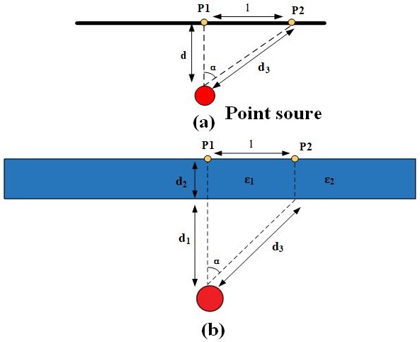
Figure 1: (a) Phase difference between two points for the air. (b) Proposed superstrate [7].
B. Principle of gain increase
An ideal Fabry–Perot resonator is composed of two parallel infinite uniform and an ideal point antenna. It is assumed that the electromagnetic wave has no loss in the transmission state, and the edge effect is ignored. The radiation source rice emits electromagnetic waves with a wavelength of and a frequency of f. In the case of GND total reflection, its reflection coefficient is . The reflection coefficient of FSS is p, that is, the reflection coefficient is. Since the distance between the radiation plates is d, According to eqn (3) the electric field amplitude changes to , after multiple reflections and transmissions [8].
| (3) |
Among them, is the phase difference between electromagnetic beam n and beam 1, is the directional pattern in the direction of a degree from the radiation source and the GND normal line, and the electric field amplitude is. Therefore, the phase difference between any beam and beam 1 can be written as [8]
| (4) |
Thus, the far-field energy density S can be obtained as
| (5) |
So when is 0, S will be the maximum [8]
| (6) |
Where is the energy density in this direction when the overburden is not load. According to eqn (6), the far-field energy density of the antenna is related to the value of p. Therefore, the antenna gain can be improved by carrying FSS matching with the antenna [9]. In addition, the height of MS distance from the antenna L can also be calculated from eqn (7)
| (7) |
III. DESIGN AND SIMULATION OF THE PROPOSED ANTENN
The designed antenna is fed by a coaxial feeding mode and is divided into the metal–dielectric–metal three-layer structure. GND regulates resonant frequency and increases the impedance bandwidth by slot. The middle metal patch at the top of the antenna is set with four annular slots for parameter regulation, and the square patch with regular arrangement is set up to improve the antenna gain. The primary radiating element and the bottom layer of the antenna are separated by a 1.6 mm thick FR4 dielectric layer (loss tangent = 0.002 and relative permittivity 4.4).
An MS was used in the structure by combining a periodic structure of unit cells which is composed of a symmetric curl structure to significantly improve the gain of the antenna. The MS layer is also organized on the FR4 dielectric with a thickness of 1.6 mm. Moreover, the bottom layer of the antenna is separated by a 1.6 mm thick FR4 dielectric layer (loss tangent = 0.002 and relative permittivity 4.4). The optimized geometric dimensions of the 3-D structure and the back view and top view of the traditional antenna are shown in Figure 2 (a)–(c), respectively.
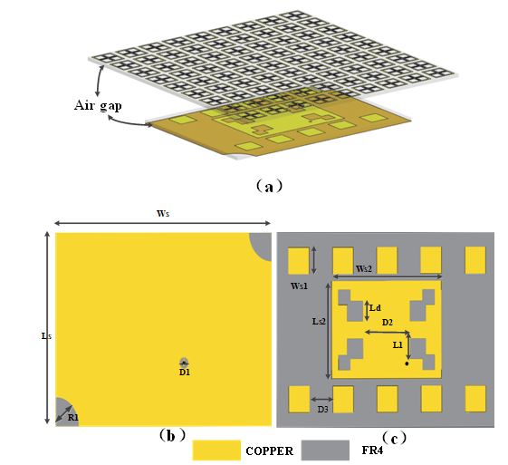
Figure 2: (a) 3-D antenna model, (b) Conventional antenna back view, (c) Top view of the conventional patch (Design optimization parameters: Ws = 74.52 mm, Ls = 51.8 mm, D1 = 3.0 mm, R1 = 8 mm, Ws1 = 7 mm, Ws2 = 37.26 mm, Ld = 5.3 mm, Ls2 = 25.9 mm, D2 = 16.06 mm, D3 = 8 mm, L1 = 6 mm).
A 50 lumping feed was fed into this antenna using an SMA connector through the substrate and ground layer. The designed antenna works in WIFI and GSM 1800 MHz, two regions in which the operational band can be tuned by just adjusting the location of the shorting via and dimensions of the periodic slots. The designed evolution. Further study is carried out to identify the effects of various parameters in terms of the impedance bandwidth and return loss.
The designed evolution of the conventional patch antenna and with three different steps. The corresponding return loss responses are shown in Figure 3. It is clear from that the introduction of the MS just above the conventional patch results in the lowering of the operating frequency of the antenna. In the low frequency band, the bandwidth changes from 1.83–1.87 GHz to 1.79–1.83 GHz without significant reduction. Further study shows that the bandwidth of the proposed antenna at 2.4 GHz increases by 4.1%, and the return loss reaches 27 dB. It is further observed that the introduction of the 99 order of the MS improves the bandwidth of the proposed antenna. For further study, the parametric studies are carried out to identify the effects of various parameters in terms of the impedance bandwidth and return loss.
A. Layout of the microstrip patch
Initially, microstrip patch antenna was patterned on a 1.6 mm thick low-cost FR4 substrate, which is shown in Figure 2 (c). Antenna operates at 2.4 GHz with a –10 dB impedance bandwidth of 3.2% and a realized gain of 5.07 dBi. The microstrip patch was reformed into a fractal shape by etching the four different fractal square-shaped slots, the antenna gain increases to 5.27 dBi. The impedance bandwidth is increased by 3.02% at 2.4 GHz.
Under this arrangement, as shown in Figure 4 (a), firstly, change the feeding position to achieve impedance matching. Then adjust the patch size to the experimental band as shown in Figure 4 (b). Finally, the antenna parameters are further optimized to obtain better far-field gain.
B. Layout of the MS unit design
In this design, the performance of the conventional patch antenna shown as in Figure 2 was enhanced by the inclusion of the MS. Initially, the MS layer is separated from the conventional patch by an air spacer and is further replaced by the insulation pillar.
The MS consists of periodic unit cells with a 99 order. The unit cell consists of a centrosymmetric curl structure as shown in Figure 5 (a), (b). According to the directional coefficient of the previously designed antenna, the theoretical reflection coefficient p that the reflector should reach is about 0.57 from the eqn (8) [8].
| (8) |
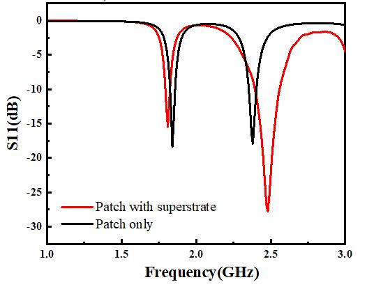
Figure 3: Plot of S11(dB) with respect to the frequency (GHz) of the proposed antenna.
Then the corresponding structure of the metamaterial is obtained by LC equivalent circuit analysis as shown in Figure 5 (a), (b) and the optimization simulation results are close to the theoretical calculation results. The primitive electromagnetic properties, such as the effective permittivity and permeability, the concerned MS layer have been studied. The real and imaginary parts of the effective permittivity are shown in Figure 5 (c), while the same for effective permeability are shown in Figure 4 (d). At the left and right resonant frequency band of 3.3 GHz metamaterial, its effective permeability and effective permittivity are negative, that is (DNG) structure.
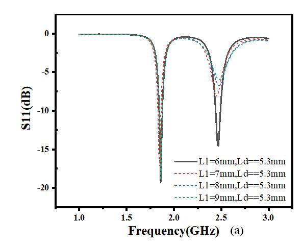
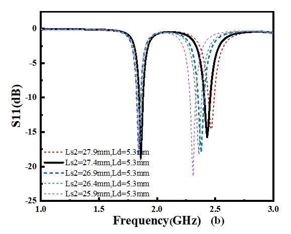
Figure 4: (a) Plot of S11(dB) with respect to the frequency at constant Ld = 5.3 mm and L1 variations. (b) Plot of S11(dB) with respect to the frequency at constant Ld = 5.3 mm and Ls2 variations.
It can be clearly observed from Figure 5 (c) and (d) that the MS layer about 3.3 GHz is DNG material. DNG material is suitable for producing narrow beam radiation in far field. As a consequence, the engineered structures can be utilized for making small and reconfigurable antennas.
C. Design antenna combined simulation with MS
Due to the low frequency of the antenna, this experiment needs to achieve the design of metamaterial unit miniaturization according to theoretical derivation. By adjusting the shape of the metamaterial, the FSS material can reduce the stopband to a lower frequency band in a limited space. It is found that the FSS material can be miniaturized by bending the patch and increasing the effective electric length of the patch.
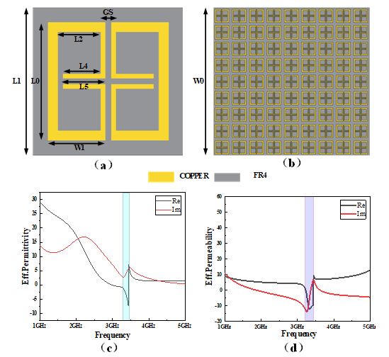
Figure 5: (a) Unit cell of MS (designed parameters: L0 = 8 mm, W1 = 3.8 mm, Gs = 0.4 mm, L2 = 3.1 mm L4 = 2.5 mm, L5 = 2.8 mm) with (b) 99 order MS, (c) effective permittivity of the unit cell, and (d) effective permeability of the unit cell.
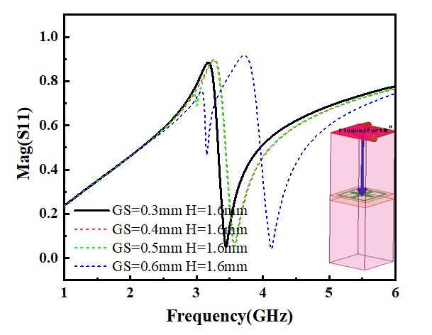
Figure 6: Plot of mag with respect to the frequency at constant H = 5.3 mm and GS variations.
Under this arrangement, as shown in Figure 6, firstly, the gap GS of the symmetric metamaterial structure was changed to make the simulation data coincide with the theoretical calculation data. Then, the model was simulated by using the master–slave boundary to achieve the appropriate reflection amplitude. Combined with theoretical derivation and simulation results, the MS reflection coefficient is about 0.57 at 2.4 GHz, and according to eqn (7), the MS coverage height L is about 15.5 mm.
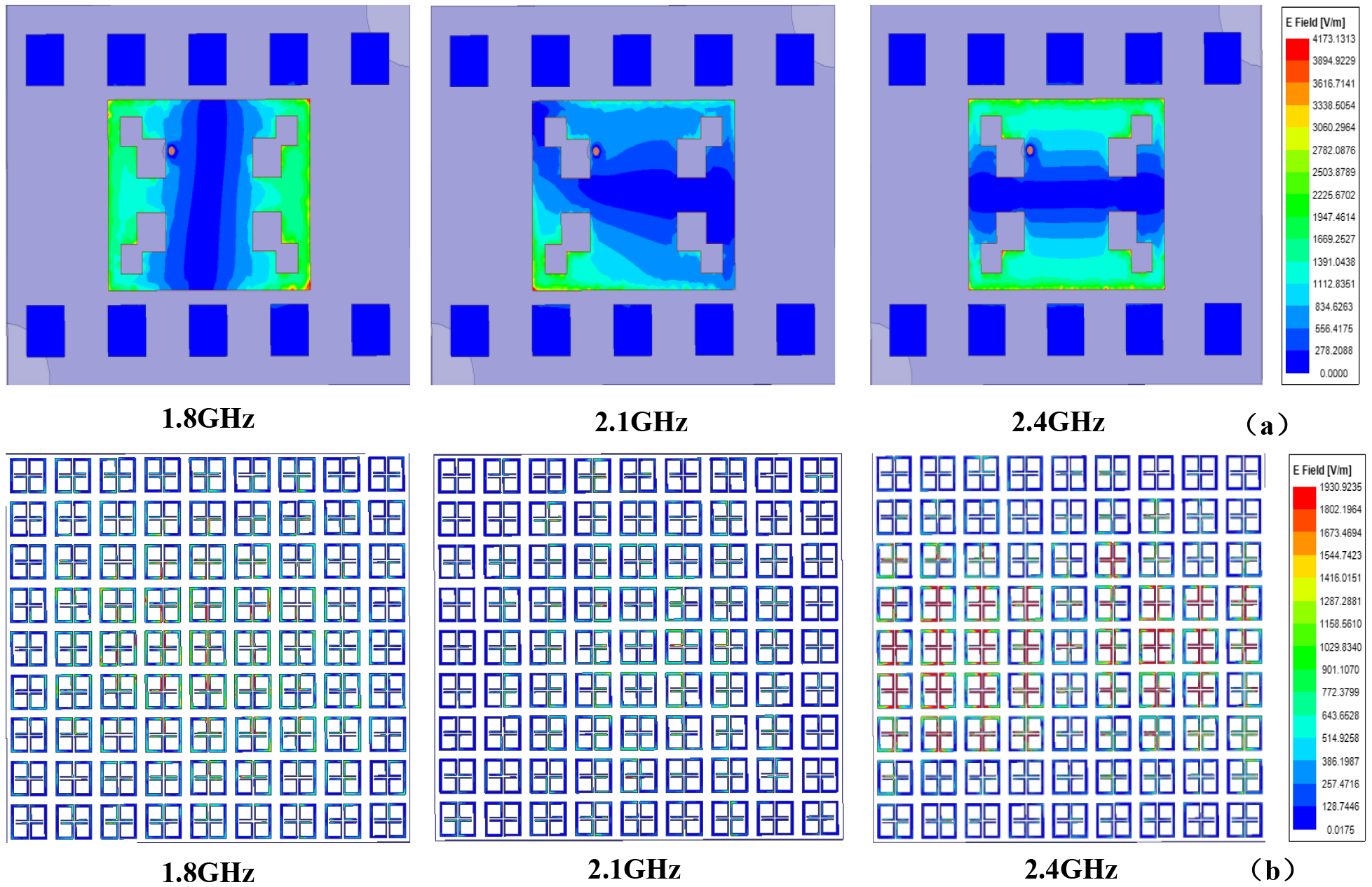
Figure 7: Surface current distributions at (a) top and (b) 99 order MS at different operating frequencies within the proposed structure.
The electric field distributions of the top and bottom surfaces of the conventional patch antenna at various operating frequencies of 1.8 GHz, 2.1 GHz, and 2.4 GHz are shown in Figure 7 (a), respectively. With the increase of antenna frequency, the distribution of the antenna electric field shifts from the left and right edges of the antenna to the upper and lower edges [8, 9]. The electric field distributions in the top MS layer at the aforementioned frequencies are also shown in Figure 7 (b). It is observed from Figure 7 that the field distribution is maximum along the edge of the antenna and the intensity of the fields is very high among the unit cells of the MS layer.
In Figure 7 (a), (b), as shown in the same frequency, we also studied respectively on the surface of the patch antenna designed three surface current [23, 24]. The results show that the surface currents around the antenna feed and MS layer are stronger at the corresponding frequencies. The current distribution path on the top surface increased as the four-unit cell slot of the fields is very high among the unit cells of the MS layer.
IV. FABRICATION AND TEST OF THE PROPOSED ANTENNA
The antenna prototype shown in Figure 2 was fabricated using the PCB prototyping instrument [25]. The top and rear views of the fabricated sample are shown in Figure 10 (a), (b), respectively. The complete 3-D sample is shown in Figure 10 (c). The antenna prototype was tested by HP Network Analyzer as shown in Figure 10 (e). The return loss profile of the prepared sample as shown in Figure 10 (e) was measured, and it can be seen that the 10 dB impedance bandwidth measured by the experiment in the range of 1.8 GHz and 2.4 GHz matched well with the corresponding simulation.
The E-plane and H-plane radiation pattern measurements of the fabricated antenna were carried out within the anechoic chamber. The test environment is shown in Figure 10 (a), (b). The far-field antenna gains of the proposed prototype with respect to frequencies are shown in Figure 10. It can be seen that the gain of the simulated quantity increased nearly three times before and after adding MS, and the simulated quantity was basically consistent with the real measurement.

Figure 8: (a) Top view. (b) Rear view. (c) 3-D view of the proposed antenna. (d) S-parameter measurement using VNA (e) Plot of measured S11(dB) with respect to frequency.

Figure 9: (a) Microwave anechoic chamber measures far-field radiation. (b) The transmitting antenna serves as the signal source.
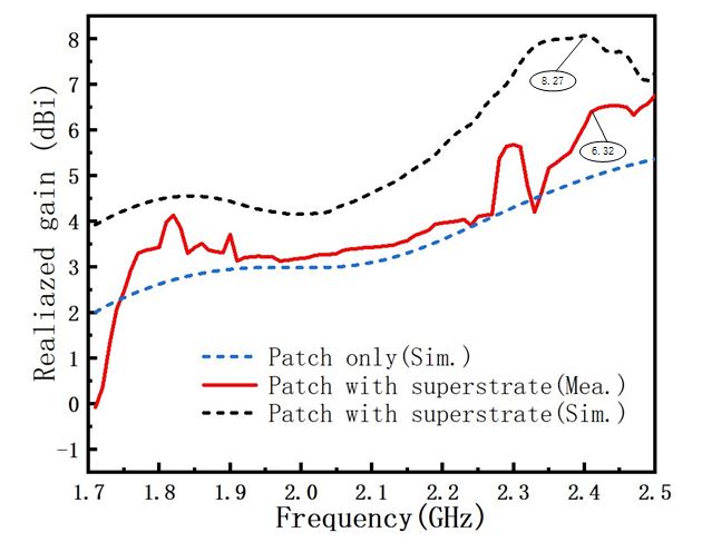
Figure 10: Gain in the antenna bandwidth for the patch antenna with and without the superstrate.
As shown in Table 1, the maximum gain of analog image and measured image of antenna at 1.8 GHz is 4.49 dBi and 4.13 dBi, respectively. The maximum gain in 2.4 GHz analog mode and measurement mode is 8.27 dBi and 6.32 dBi. The maximum efficiency of analog image and measured image at 1.8 GHz is 45.15% and 41.31%, respectively. The maximum efficiency in 2.4 GHz analog mode and measurement mode is 69.15% and 62.17%, respectively. Table 2 shows the performance comparison between the proposed antenna and other antennas. It can be concluded from the table that the proposed TA has the advantages of high gain and reflection efficiency. Most importantly, it has dual frequency characteristics.
Table 1: The simulation results are compared with the measured results
| Results | Frequency | Return loss | Max. gain | Efficiency |
| (GHz) | (dB) | (dBi) | (%) | |
| Simulated | 1.8 | 17.1 | 4.49 | 45.15 |
| Measured | 1.8 | 14.3 | 4.13 | 41.31 |
| Simulated | 2.4 | 27.1 | 8.27 | 69.15 |
| Measured | 2.4 | 17.3 | 6.32 | 62.17 |
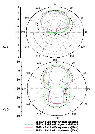
Figure 11: (a) Antenna far-field simulation and measured figure at 1.8 GHz. (b) Antenna far-field simulation and measured figure at 2.4 GHz.
In addition, as shown in Figure 11, the simulated radiation mode is very consistent with the measured radiation mode.
The difference between the simulation and design results may occur due to the fabrication tolerances (which can be due to the slight air gap between these dielectric layers at the time of fabrication, soldering between the dielectric substrate and the SMA connector, or the copper loss of the FR4 dielectric at the time of polishing). In addition, the shift may be due to the insertion loss of the SMA connector.
Table 2: The comparison between the proposed TA and other published TA
| Ref. | Frequency (GHz) |
Return loss (dB) |
Max. gain (dBi) |
Relative bandwidth (–10dB) (%) |
| [7] | 5.7 | 13 | 8.9 | 3.8 |
| [19] | 10.5 | 24 | 7.57 | 7.6 |
| [23] | 4.5 | 24 | 7.5 | 2.8 |
| This Work | 1.8 2.4 |
17.1 27.1 |
4.49 8.27 |
2 7.6 |
V. CONCLUSION
This communication proposed a low-frequency MS structure and the use of a hyperlayer to increase the antenna gain. By adjusting the MS characteristic, the reflection coefficient can be changed to form a large area of in-phase electric field on the hyperlayer surface. The proposed antenna operates at 2.4 GHz frequency with a fractional bandwidth of 6.9% and a significantly enhanced gain of 8.27 dBi at the same operating frequency. The simulated and the experimental results validate well, therefore, demonstrating a good antenna performance. Since there are a large number of electromagnetic waves in this frequency band in the environment, it can be extended to the study of RF energy collection and other aspects.
ACKNOWLEDGMENT
This work was supported and funded by the National Natural Science Foundation of China (51965047), Inner Mongolia Science and Technology Research Project (2020GG0185), Research Startup Fund of High-level Talents Introduction in 2018(21700-5185131, 21700-5185128).
REFERENCES
[1] M. E. Badawe, T. S. Almoneef, O. M. Ramahi, “A true metasurface antenna,” Sci Rep. vol. 6, no. 1, pp. 1-8, May 2016.
[2] S. Zhang, X. Chen, G. F. Pedersen, “Mutual coupling suppression with decoupling ground for massive MIMO antenna arrays,” IEEE Transactions on Vehicular Technology. vol. 68, no. 8, pp. 7273-7282, Aug. 2019.
[3] S. Liu, D. Yang, Y. Chen, X. Zhang, Y. Xiang, “High isolation and low cross-polarization of low-profile dual-polarized antennas via metasurface mode optimization,” IEEE Transactions on Antennas and Propagation., vol. 69, no. 5, pp. 2999-3004, May 2020.
[4] J. Su, J. Liu, Z. Li, L. Y. Yang, “Full and independent manipulation of Co- and Cross-polarized waves with metasurface,” Applied Computational Electromagnetics Society Journal, vol. 34, no. 11, pp. 1653-1661. Nov. 2019.
[5] F. H. Lin and Z. N. Chen, “Low-profile wideband metasurface antennas using characteristic mode analysis,” IEEE Trans. Antennas Propagation., vol. 65, no. 4, pp. 1706-1713, Apr. 2017.
[6] W. An, Y. Li, H. Fu, J. Ma, W. Chen, and B. Feng, “Low-profile and wideband microstrip antenna with stable gain for 5G wireless applications,” IEEE Antennas and Wireless Propagation. Letters., vol. 17, no. 4, pp. 621-624, Apr.2018.
[7] J. H. Kim, C.-H. Ahn, and J.-K. Bang, “Antenna gain enhancement using a holey superstrate,” IEEE Trans. Antennas Propagation., vol. 64, no. 3, pp. 1164-1167, Mar. 2016.
[8] K. Xingjian, Antenna Principle and Design. National Defense Industry Press, 1995.
[9] F. Liu, J. Guo, L. Zhao, G. L. Huang, and Y. Yin, “Dual-band metasurface-based decoupling method for two closely packed dual-band antennas,” IEEE Transactions on Antennas and Propagation, vol. 68, no. 1, pp. 552-557, Jan. 2020.
[10] H.-P. Li, G.-M. Wang, X.-J. Gao, J.-G. Liang, and H.-S. Hou, “A novel metasurface for dual-mode and dual-band flat high-gain antenna application,” IEEE Trans. Antennas Propagation., vol. 66, no. 7, pp. 3706-3711, Jul. 2018.
[11] M. A. Qureshi, A. Aziz, A. Amin, H. F. Rasool, F. Hayat, “Design of a new wideband single-layer reflective metasurface unit cell for 5G-communication,” Applied Computational Electromagnetics Society Journal, vol. 35, no. 8, pp. 975-978. Oct. 2020.
[12] J. Ghosh, D. Mitra, and S. Das, “Mutual coupling reduction of slot antenna array by controlling surface wave propagation,” IEEE Trans. Antennas Propagation., vol. 67, no. 2, pp. 1352-1357, Feb. 2019.
[13] W. Yang, L. Gu, W. Che, Q. Meng, Q. Xue, and C. Wan, “A novel steerable dual-beam metasurface antenna based on controllable feeding mechanism,” IEEE Trans. Antennas Propagation., vol. 67, no. 2, pp. 784-793, Feb. 2019.
[14] E. Delihasnlar and A. H. Yuzer, “Wearable textile fabric based 3D metamaterials absorber in X-band,” Applied Computational Electromagnetics Society Journal, vol. 35, no. 2, pp. 230-236, Feb. 2020.
[15] H. Bai and G. Wang, “A multistate high gain antenna based on metasurface,” International Journal of RF and Microwave Computer-Aided Engineering, vol. 30, no. 4, 2020.
[16] S.-H. Zhu, X.S. Yang, J. Wang, N.-S. Nie, and B.-Z. Wang, “Mutual coupling reduction of +45dual-polarized closely spaced MIMO antenna by topology optimization,” IEEE Access, vol. 8 pp. 29089-29098, Jan. 2020.
[17] M. Li, B. G. Zhong, and S. W. Cheung, “Isolation enhancement for MIMO patch antennas using near-field resonators as coupling-mode transducers,” IEEE Trans. Antennas Propagation, vol. 67, no. 2, pp. 755-764, Feb. 2019.
[18] D. Samantaray and S. Bhattacharyya, “A gain-enhanced slotted patch antenna using metasurface as superstrate configuration,” IEEE Trans. Antennas Propagation, vol. 68, no. 9, pp. 6548-6556, Sep. 2020.
[19] J. Z Tang, X. Chen, F. Fa5raz, Q. Zhang, and S. Zhang, “A metasurface superstrate for mutual coupling reduction of large antenna arrays,” IEEE Access, vol. 8, pp. 126859-126867, Jul. 2020.
[20] M. I. Pasha, C. Kumar, and D. Guha, “Simultaneous compensation of microstrip feed and patch by defected ground structure for reduced cross polarized radiation,” IEEE Trans. Antennas Propagation, vol. 66, no. 12, pp. 7348-7352, Dec. 2018.
[21] S. Liu, D. Yang, Y. Chen, X. Zhang, and Y. Xiang, “High isolation and low cross-polarization of low-profile dual-polarized antennas via metasurface mode optimization,” IEEE Trans. Antennas Propagation, vol 69, no. 5, pp. 2999-3004, May 2021.
[22] T. Li and Z. N. Chen, “Wideband sidelobe-level reduced Ka-band meta-surface antenna array fed by substrate-integrated gap waveguide using characteristic mode analysis,” IEEE Trans. Antennas Propagation, vol. 68, no. 3, pp. 1356-1365, Mar. 2020.
[23] P. P. Kumar, K. Sreelakshmi, B. Sangeetha, and S. Narayan, “Metasurface based low profile reconfigurable antenna,” International Conference on Communication and Signal Processing (ICCSP), 2017.
[24] S. Liu, D. Yang, Y. Chen, K. Sun, X. Zhang, and Y. Xiang, “Low-profile broadband metasurface antenna under multimode resonance” IEEE Antennas and Wireless Propagation Letters, vol. 20, no. 9, pp. 1696-1700, Sep. 2021.
[25] A. Sharma, D. Gangwar, B. K. Kanaujia, S. Dwari, and S. Kumar, “Design of a wideband polarisation conversion metasurface and its application for RCS reduction and gain enhancement of acircularly polarized antenna,”IET Microwaves. Antennas Propagation, vol. 13, no. 9, pp. 1427-1437, May 2019.
BIOGRAPHIES

HuQiang Tian received bachelor degree in Communication Engineering from in Inner Mongolia Normal University, Hohhot, China, in 2019. From 2019, he pursued his Master degree in Inner Mongolia University. His research Interest are transmitarray antenna and frequency selective surface.

JunLin Wang received a doctor’s degree in engineering in Instrument Science and technology of Zhong-bei University. He is currently working in the College of electronic information engineering, Inner Mongolia University, Hohhot, China. His research interests are micro nano RF devices (antennas, filters, couplers, etc.), metamaterial antennas.

Ding Hanreceived a doctor’s degree in agricultural electrification and automation engineering from Inner Mongolia Agricultural University. At present, he works in the school of electronic information engineering of Inner Mongolia University in Hohhot, China. His research interest is artificial intelligence.

Xin Wang received a doctor’s degree in engineering in Instrument Science and technology of Zhong-bei University. She is currently working at the College of electronic information engineering, Inner Mongolia University, Hohhot, China. Her research interests are micro nano RF devices (antennas, filters, couplers, etc.), metamaterial antennas.
ACES JOURNAL, Vol. 36, No. 12, 1586–1593.
doi: 10.13052/2021.ACES.J.361210
© 2021 River Publishers