Triangular Ring Patch Antenna Analysis: Neuro-Fuzzy Model for Estimating of the Operating Frequency
Ahmet Kayabasi
Department of Electrical and Electronics Engineering
University of Karamanoglu Mehmetbey, Karaman, 70100, Turkey
ahmetkayabasi@kmu.edu.tr
Submitted On: June 7, 2021; Accepted On: September 9, 2021
Abstract
In this study, a neuro-fuzzy (NF) analysis method is suggested for the estimation of the operating frequency of triangular ring patch antennas (TRPAs) that operate at ultra high band applications. Although the analysis of regular-shaped patch antennas (PAs) such as rectangular, triangle, and circle is easy, analysis of irregularly shaped patch antennas is difficult and time consuming. Here, this great effort and time has been eliminated by using an artificial intelligence technique such as NF. To create a data set for NF, 100 TRPAs with different physical and electrical properties (L, l, h, and ) are simulated by using an electromagnetic simulator program. The currency and accuracy of the proposed approach is then confirmed on the measurement results of a prototype TRPA fabricated in this study. The results of NF model are compared with the simulation/measurement results and previously the method published in the literature.
Index Terms: analysis, neuro-fuzzy, operating frequency, patch antenna, triangular ring patch antenna.
I. INTRODUCTION
Patch antennas (PAs) have significant advantages such as low size, lightness, robustness, ease of production, low production cost, and physical compatibility with the surfaces. Because of these advantages, PAs are widely used in portable/non-portable wireless communication applications that require miniaturized geometry [1]. The substrates with a high dielectric constant can be used to reduce the antenna size for miniaturized mobile communication devices, but this leads to a decrease in parameters such as performance efficiency and bandwidth [1]. The miniaturized PAs can be constructed by utilizing some modifications such as shorting pins, slits or slots on the traditional rectangular, triangular, and circular geometry structures [1]. Triangular ring patch antennas (TRPAs) are constructed by triangular slot-loading in the center of the equilateral triangular patch [2, 3]. Triangular patch antennas (TPAs) with the same dimensions, the operating frequency is reduced due to slot-loading into the triangular patch. For the same operating frequency, the size of TRPA reduces compared to the TPA [2, 3].
Antenna analysis process covers the calculation of antenna performance parameters such as operating frequency, bandwidth, and gain. Several analytical and numerical methods having some disadvantages are generally used for analysis process [4]. The numerical methods give good results by using mixed mathematical operations. The numerical methods such as finite difference time domain method, finite element method, and method of moment (MoM) require much more time in solving Maxwell’s equations including integral and/or differential computations. So, it becomes time consuming since it repeats the same mathematical procedure even if a minor change in geometry is carried out. Moreover, the analytical methods such as the cavity model and the transmission line model are accurate but they are based on physical assumptions. Analytical methods give a physical view of antenna radiation properties. The main difficulty of analytical models is their limited input impedance for accuracy at the resonant frequency and for non-thin substrates. According to the instantaneous phase of the signal applied to the antenna, the minimum and maximum continuously changing electric field can be mentioned. The electric field does not stop abruptly, as in the space around the patch, and stretches the outer frame of the patch somewhat. These area extensions are known as fringe areas and cause the patch to spread. These methods are more suitable for conventional MAs because of their regular shapes. In addition, these approaches require a new solution for every small change in the patch geometry [4]. For this reason, artificial intelligence techniques are widely preferred as more accurate and faster alternative methods in order to overcome these difficulties of traditional techniques in the analysis process of PAs [2, 3, 4, 5, 6, 7, 8, 9, 10, 11, 12, 13, 14, 15, 16, 17, 18]. The precise mathematical formulations in complex methods involve a large number of numerical operations that result in rounding errors and may require experimental adjustments to theoretical results. Obtaining results from these methods takes a long time and these methods are not very suitable for computer aided design. Features such as learning ability, easy applicability to different problems, generalization feature, less information requirement, fast processing, and easy implementation have made artificial intelligence popular in recent years. Artificial intelligence models such as Artificial Neural Network (ANN) [19], Fuzzy Logic (FL) [20], Support Vector Machine (SVM) [20], and Neuro-Fuzzy (NF) [22] eliminate the complex mathematical procedures and time consuming for processes of antenna design. These models have been used extensively for the analysis of various PAs in the literature [5, 6, 7, 8, 9, 10, 11, 12, 13, 14, 15, 16, 17]. In [5, 6, 7, 8, 9, 10, 11, 12, 13, 14, 15, 16, 17], analysis studies were carried out to determine some performance parameters of PAs having various shapes with artificial intelligence techniques such as ANN, SVM, and NF.
In this study, an NF-based artificial intelligence model is proposed for the analysis of TRPAs in terms of operating frequency (fr). For this purpose, the simulation of 100 TRPAs was carried out by a 3D full-wave simulator based on MoM [23] and the dataset for the NF model was created. The number of 75 and 25 TRPA datasets are used to training and testing the NF model’s accuracy, respectively. In addition, the NF model is verified by the measurement data of the TRPA fabricated for this study.
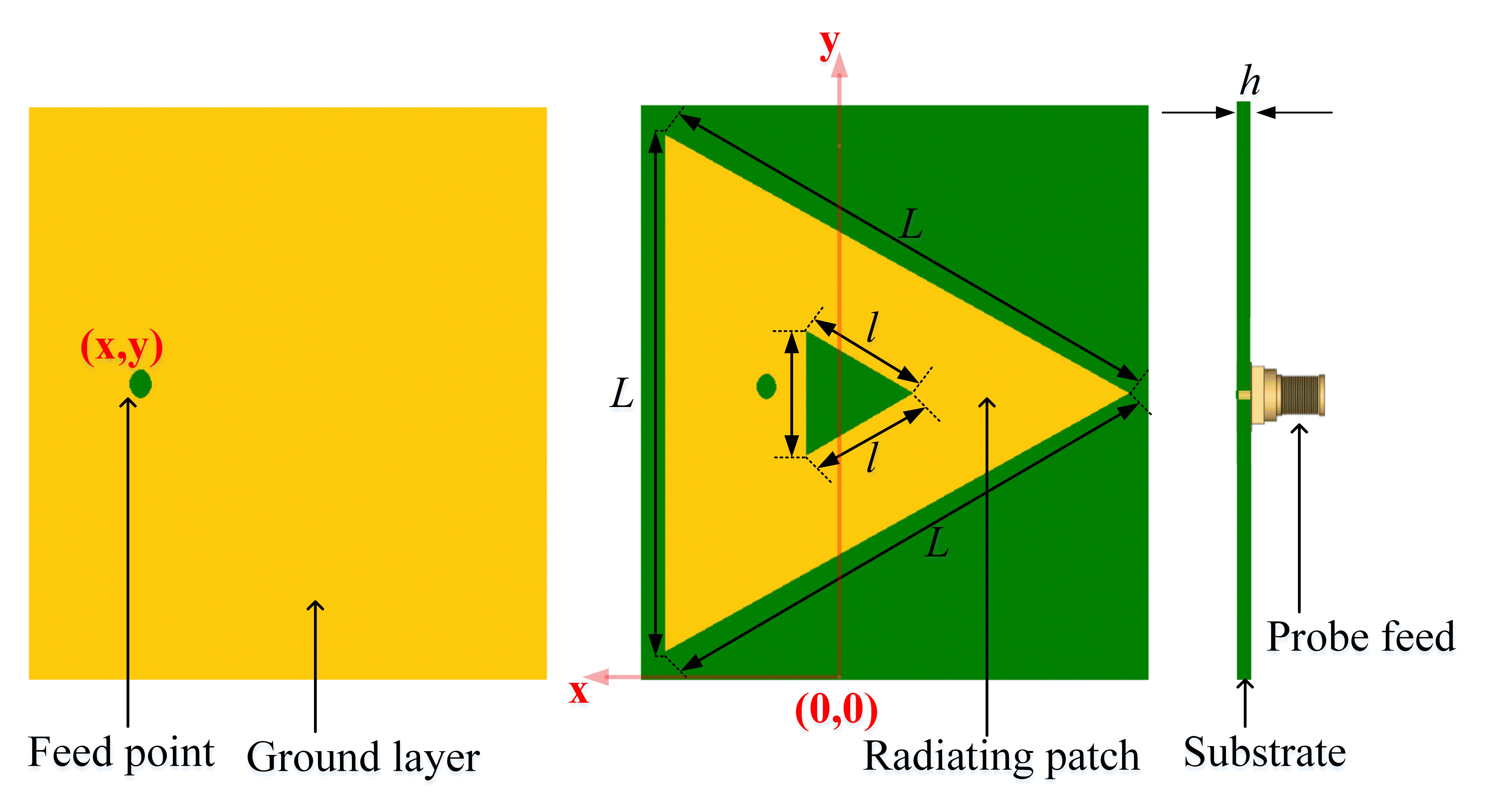
Fig. 1. Geometry of the TRPA.
II. TRPA STRUCTURE AND SIMULATION PROCESS
The TRPA structure is obtained by slotting with “l” dimensional triangle in the middle of the “L” dimensional triangle as shown in Figure 1. The formed patch is placed on a substrate having dielectric constant and h as thickness. The x and y represent the feeding point of the TRPA. The triangular slotting in the center of the TPA causes a reduction in the operating frequency compared to a TPA of the same size. Also, TRPA is smaller than TPA at the same operating frequency, and these results are shown in Table 1.
Table 1: Comparative results of simulated TPA and TRPA
| Antenna | Patch Dimension (mm) | f [GHz] | |||
| L | l | h | |||
| TPA | 52 | 0 | 1.6 | 2.33 | 2.432 |
| TRPA | 52 | 17.2 | 1.6 | 2.33 | 2.226 |
| TPA | 52 | 0 | 1.6 | 2.33 | 2.432 |
| TRPA | 43.3 | 25.8 | 1.6 | 2.33 | 2.432 |
Table 2: Comparative results of simulated TPA and TRPA
| Number of | Patch Dimensions (mm) | Dielectric | ||
| Simulations | L | l | h | Constant () |
| 20 | 26 | 3.44, 6.88, 10.32, | 1.6, 2.5 | 2.33, 4.4 |
| 13.76, 17.2 | ||||
| 20 | 34 | 5.16, 10.32, 15.48, 20.64, | ||
| 25.8 | ||||
| 20 | 52 | 8.6, 17.2, 25.8, | ||
| 34.4, 43 | ||||
| 20 | 69 | 17.2, 25.8, 34.4, | ||
| 43, 51.6 | ||||
| 20 | 86 | 25.8, 34.4, 43, | ||
| 51.6, 60.2 | ||||
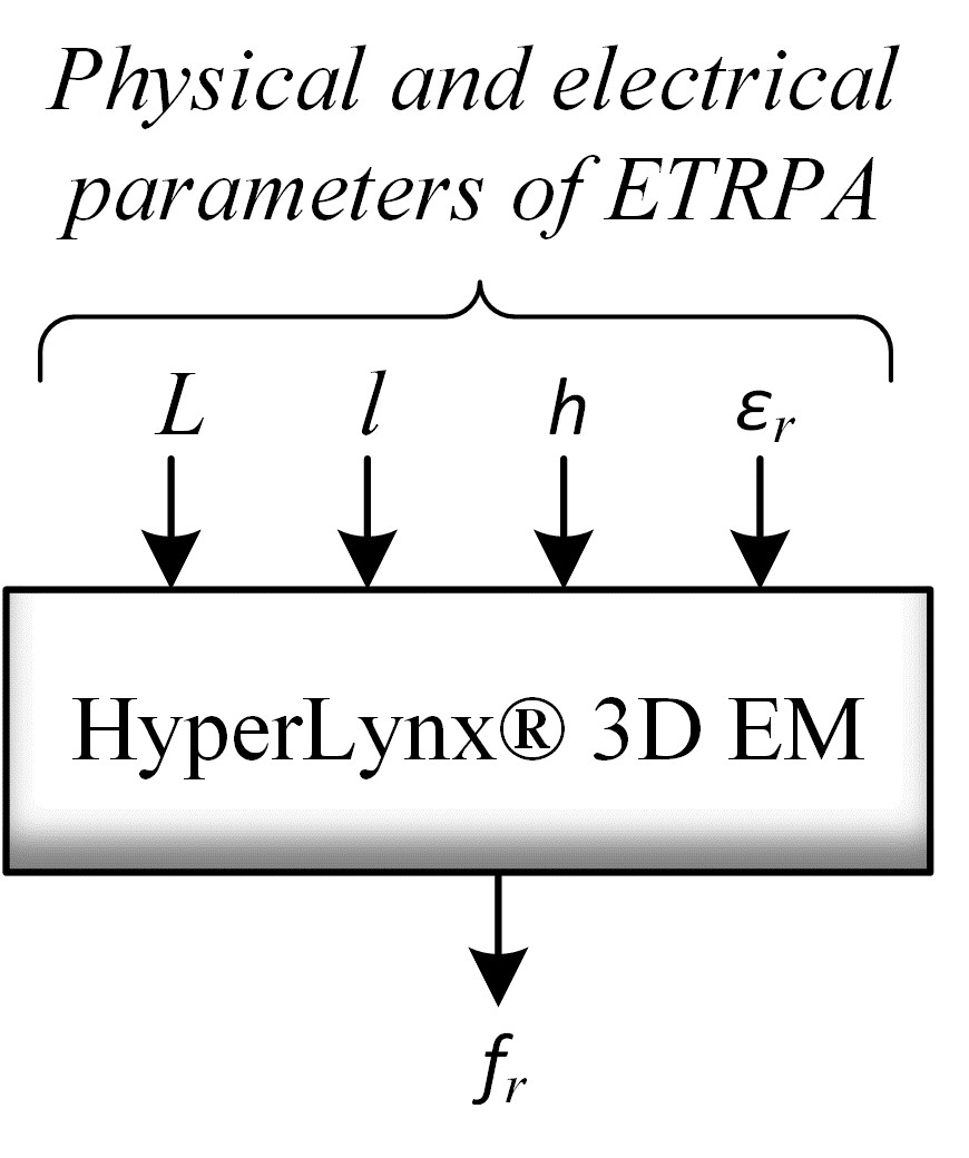
Fig. 2. Geometry of the TRPA.
Simulations of 100 TRPAs were made according to the parameters (L, l, h, and ) and the operating frequency (f) given in Table 2. Commonly used materials such as FR4 and Rogers RT/duroid 5870 were chosen as substrates in the simulations. The TRPA structures are modeled/simulated according to the topology in Figure 2 by the software HyperLynx® 3D EM [24] based MoM [23]. The software uses the MoM to analyze potentially any patch shape in the spectral domain. The only limitation on the potential of this method is the length of analytical and numerical computation required for analysis. The complex potential integral equation is solved by the software in the space domain using the MoM. A wave source of 1 Volt with coaxial feed is utilized for the TRPAs in the simulations. The TRPA models are meshed with maximum frequency of 4 GHz and lines per wavelength ratio of 40. The TRPAs are simulated between the frequency of 0 GHz and 4 GHz. The feed point of TRPAs is determined (S -10 dB) by using the HyperLynx 3D EM’s built-in optimization module.
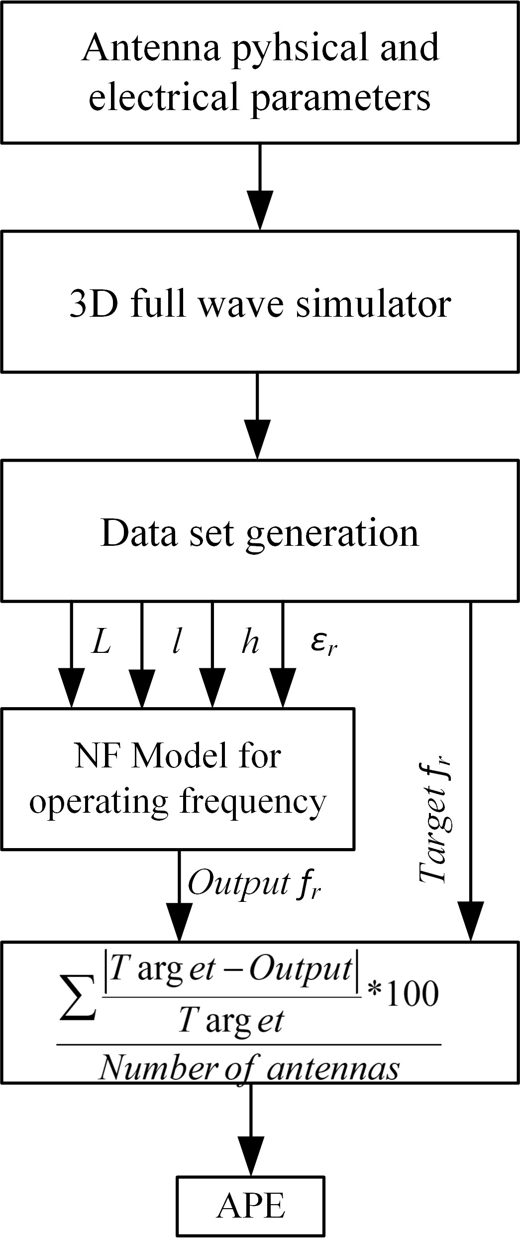
Fig. 3. The working principle of the NF model.
III. PROCESS OF NF MODEL
The steps of NF model construction to determine the operating frequency of TRPAs are shown in Figure 3. The number of 75 antenna data are used to train the NF model and it is aimed to minimize the average percentage error (APE) between targets/outputs.
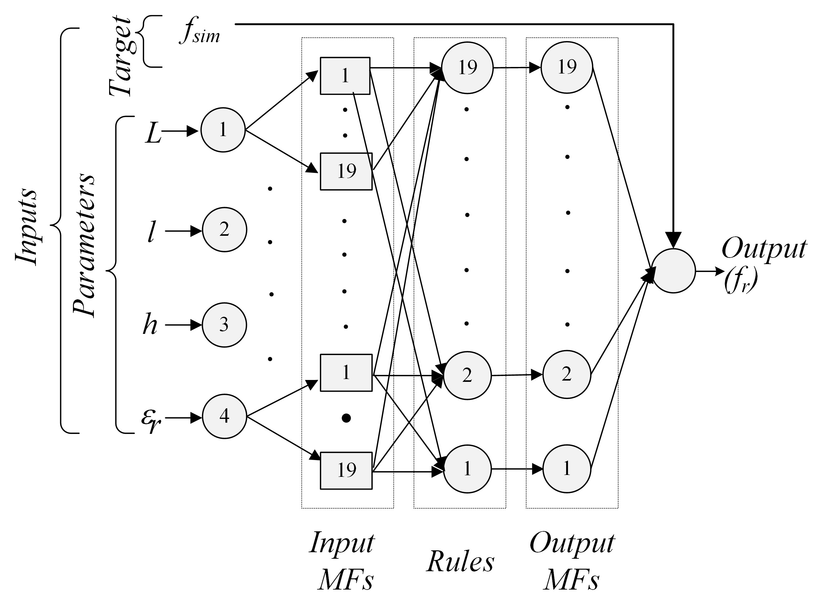
Fig. 4. The proposed NF model.
A. NF modeling and training
The NF is an important method that helps in accurate computation, estimation, prediction, and classification [22]. It is an integrated form of the ANN and fuzzy inference system (FIS) to merge the learning characteristic of the ANN with the expert knowledge of the FIS [22]. Seventy-five of the 100 TRPA datasets were used for training the NF model. In prediction of operating frequency, an NF based on Sugeno type FIS is designed as presented in Figure 4 and its set-parameters are given in Table 3. The algorithm of the NF model is coded in the platform of MATLAB®. Before the input data is presented to the NF model, it is normalized by dividing by 1000. Membership functions (MFs) of the NF model are Gaussian functions which are used for the input and linear function which is used for the output. The NF network is trained by hybrid-learning algorithm [22] associating the backpropagation algorithm and the least-square method. Considering the comparative results given in Figure 5, the results obtained from the simulations are compatible with the proposed NF model, and the APE for analysis in the training process was obtained as 0.259%.
Table 3: The used NF parameters for analysis TRPA
| Parameters | Set Type/Value |
| Input MF type | Gaussian |
| Output MF type | Linear |
| Number of inputs | 4 |
| Number of outputs | 1 |
| Number of fuzzy rules | 19 |
| Number of MFs | 19 |
| Seed value | 349097429 |
| Epochs | 150 |
| Number of nonlinear parameters | 4 x 19 x 2 = 152 |
| Number of linear parameters | 5 x 19 = 95 |
| Number of nodes | 197 |
| Number of training data pairs | 75 |
B. Testing results of analysis for TRPA
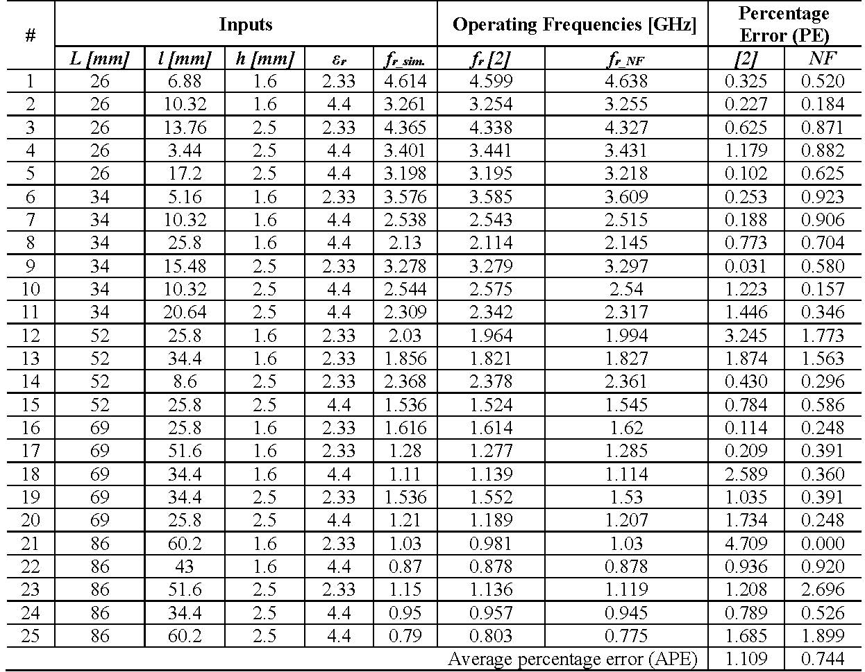
In the last section, NF model is constructed and trained with proper parameters. The accuracy of the NF model is now tested through 25 TRPA datasets not included in the training phase. The parameters of 25 simulated antennas with respective operating frequency values and the computed operating frequency values are given in Table 4. Also, NF results are compared with the results of proposed method in the literature [2]. It is seen from the results; model successfully obtains the operating frequency with APE of 0.744%. The harmony of simulation and NF model results is seen in Figure 6. The results obtained with NF are better than the method proposed in the literature [2]. Because NF shows a better approach to nonlinear problems than SVM [2].
Table 4: The comparative test results for operating frequencies of TRPAs
|
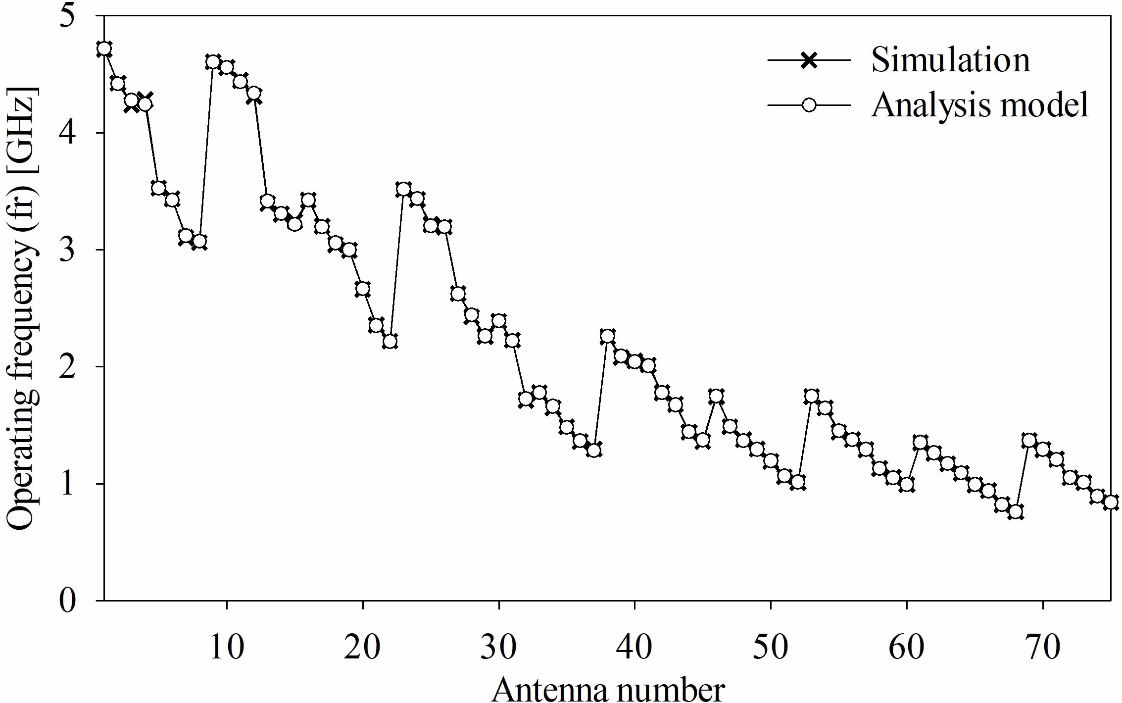
Fig. 5. Comparative results for the simulation/NF analysis model in the training process.
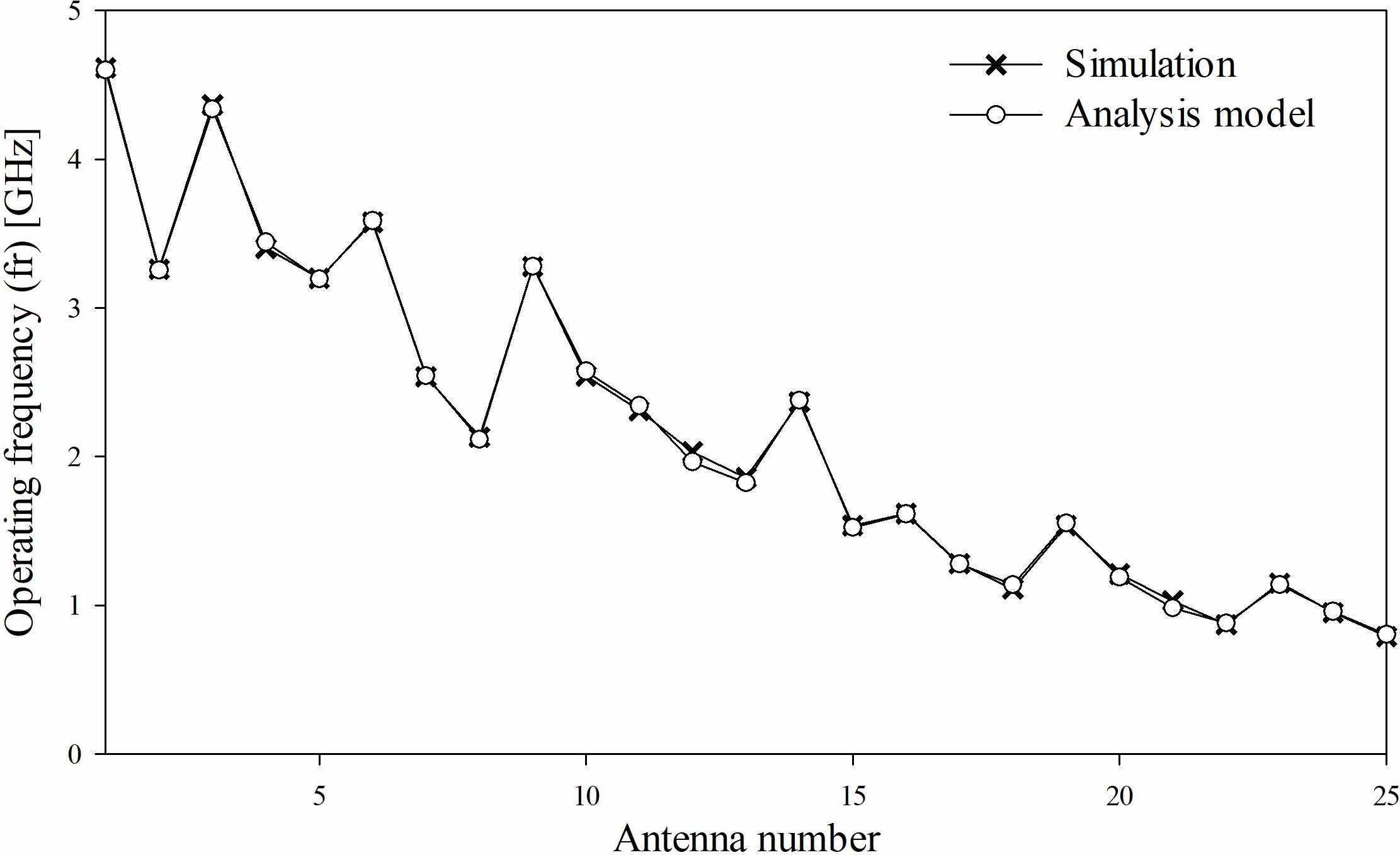
Fig. 6. Comparative results of the simulation and NF analysis model in the testing process.
IV. FABRICATION OF TRPA
The TRPA fabricated in this study is used for the accuracy of the NF analysis model. TRPA printed on FR4 PCB substrate is shown in Figure 7 and the electrical/physical properties of FR4 PCB (, tangent loss = 0.02) are given in Table 5. FR4 substrate is made of fiberglass. This substrate layer provides a solid foundation for PCBs, though the thickness can vary according to the uses of a given board. The Keysight Technologies N5224A PNA network analyzer is used to measure the prototyped TRPA. The measured S parameter is shown in Figure 8 in comparison with the simulated one. The results of measured and the analysis model are listed in Table 5 to evaluate the testing process in detail.

Fig. 7. The photograph of prototyped TRPA.
Table 5: The comparative operating frequencies
| Inputs | Operating Frequency [GHz] | ||||||
| L [mm] | l [mm] | h [mm] | f | f | [2] | f | |
| 52 | 8.6 | 1.6 | 2.22 | 2.438 | 2.468 | 2.391 | 2.425 |
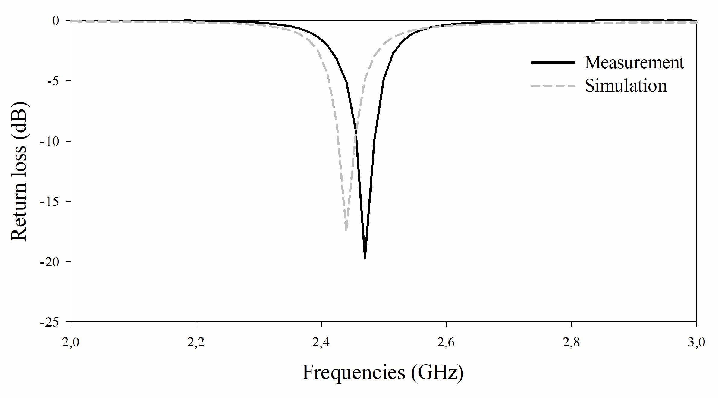
Fig. 8. The simulated and measured S11 parameters of TRPA.
From Table 5, the result of NF model is much close to the simulated/measured results. Therefore, the NF model can be successfully used to obtain the operating frequency (f) of the TRPA without handling complex mathematical functions and transformations. Moreover, the proposed NF model can be modified and developed to solve similar nonlinear electromagnetic problems.
V. CONCLUSION
In this study, the NF model is implemented for analysis of the TRPAs. For this, the NF model using Sugeno-type FIS is designed to compute the operating frequency of TRPAs. The number of 100 TRPAs having four antenna parameters is simulated to obtain the operating frequency. The NF model is trained and tested respectively with 75 and 25 datasets of the 100 TRPAs. The APE is computed as 0.259% for 75 training data and as 0.744% for 15 test data of TRPAs. According to the obtained results, the operating frequency of TRPAs is successfully computed using the proposed NF model. Also, the operating frequency values predicted in this work are compared with different calculated results reported in the literature. The NF technique may be preferred as a faster and accurate alternative method according to the traditional techniques in the analysis processes of PAs. On average, the simulation time is five minutes to find the operating frequency of a TRPA. However, this time is in the order of milliseconds by using the proposed method. It was concluded that the NF method may successfully be used to define any parameter of TRPA for analysis.
REFERENCES
[1] K. Wong, Compact and Broadband Microstrip Antennas. John Wiley & Sons, Inc., 2002.
[2] A. Kayabasi, “Analysis and synthesis of equilateral triangular ring microstrip antenna using Support vector machine,” Appl. Comput. Electromagn. Soc. J., vol. 33, no. 6, pp. 616-624, Jun. 2018.
[3] A. Kayabasi, “Soft computing-based synthesis model for equilateral triangular ring printed antenna,” AEU - Int. J. Electron. Commun., vol. l94, pp. 332-338, Sep. 2018.
[4] J. R. James, P. S. Hall, and C. Wood, Microstrip Antenna Theory and Design. Peter Peregrinus, 1981.
[5] A. Kayabasi and A. Akdagli, “Predicting the resonant frequency of E-shaped compact microstrip antennas by using ANFIS and SVM,” Wireless Pers. Commun., vol. 82, pp. 1893-1906, Jun. 2015.
[6] A. Kayabasi, A. Toktas, A. Akdagli, M. B. Bicer, and D. Ustun, “Applications of ANN and ANFIS to predict the resonant frequency of L-shaped compact microstrip antennas,” Appl. Comput. Electromagn. Soc. J., vol. 29, no. 6, pp. 460-469, Jun. 2014.
[7] K. Sabanci, A. Kayabasi, A. Toktas, and E. Yigit, “Notch antenna analysis: Artificial neural network-based operating frequency estimator,” Appl. Comput. Electromagn. Soc. J., vol. 32, no. 4, pp. 303-309, Apr. 2017.
[8] K. Guney and N. Sarikaya, “Adaptive neuro-fuzzy inference system for computing the resonant frequency of circular microstrip antennas,” Appl. Comput. Electromagn. Soc. J., vol. 19, pp. 188-197, Nov. 2004.
[9] F. Güneş, N. T. Tokan, and F. Gürgen, “A consensual modeling of the expert systems applied to microwave devices,” Int. J. RF Microw. Comput.-aided Eng., vol. 20, pp. 430-440, 2010.
[10] Y. Tighilt, F. Bouttout, and A. Khellaf, “Modeling and design of printed antennas using neural networks,” Int. J. RF Microw. Comput.-aided Eng., vol. 21, pp. 228-233, Mar. 2011.
[11] A. R. Venmathi and L. Vanitha, “Support vector machine for bandwidth analysis of slotted microstrip antenna,” Int. J. Comput. Inf. Sci., vol. 4, no. 1, pp. 67-61, 2011.
[12] A. De Khan and M. Uddin, “Prediction of slot-size and inserted air-gap for improving the performance of rectangular microstrip antennas using artificial neural networks,” IEEE Antennas Wireless Propag. Lett., vol. 12, pp. 1367-1371, Oct. 2013.
[13] E. Demircioglu, M. H. Sazlı, S. T. İmeci, and O. Sengul, “Soft computing techniques on multiresonant antenna synthesis and analysis,” Microw. Opt. Technol. Lett., vol. 55, no. 11, pp. 2643-2648, Nov. 2013.
[14] L. Merad, F. T. Bendimerad, and S. M. Meriah, “Design and resonant frequency calculation of rectangular microstrip antennas,” Int. J. Numer. Model. El., vol. 24, no. 2, pp. 144-153, Feb. 2011.
[15] N. K. Saxena, M. Khan, P. K. S. Pourush, and N. Kumar, “Neural network analysis of switchability of microstrip rectangular patch antenna printed on ferrite material,” Int. J. RF Microw. Comput.-aided Eng., vol. 20, no. 1, pp. 1-5, 2010.
[16] N. T. Tokan and F. Gunes, “Support vector characterization of the microstrip antennas based on measurements,” Prog. Electromagn. Res. B., vol. 5, pp. 49-61, 2008.
[17] Z. Qi-Jun, K. C. Gupta, and V. K. Devabhaktuni, “Artificial neural networks for RF and microwave design-from theory to practice,” IEEE Trans. Microw. Theory Tech., vol. 51, pp. 1339-1350, Apr. 2003.
[18] A. Akdagli, A. Kayabasi, and I. Develi, “Computing resonant frequency of C-shaped compact microstrip antennas by using ANFIS,” Int. J. Elec., vol. 102, pp. 407-417, Mar. 2015.
[19] S. Haykin, Neural Networks: A Comprehensive Foundation. Macmillan College Publishing Company, New York, 1994.
[20] L. A. Zadeh, “Fuzzy logic,” Computer (Long Beach Calif), vol. 21, pp. 83-93, 1988.
[21] V. Vapnik and A. Chervonenkis, “The necessary and sufficient conditions for consistency in the empirical risk minimization method,” Pattern Recognit. Image Anal., vol. 1, pp. 283-305, Jan. 1991.
[22] J. R. Jang, “ANFIS: adaptive-network-based fuzzy inference system,” IEEE Transactions on Systems, Man, and Cybernetics, vol. 23, no. 3, pp. 665-685, 1993.
[23] R. F. Harrington, Field Computation by Moment Methods. IEEE Press, Piscataway, NJ, 1993.
[24] HyperLynx® 3D EM, Version 15, Mentor Graphics Corporation, 8005 SW Boeckman Road, Wilsonville, OR 97070.
BIOGRAPHIES

Ahmet Kayabasi was born in 1980. He received his B.S. and M.S. degrees in electrical and electronics engineering from Selcuk University, Turkey, in 2001, 2005 respectively. In 2015, he received his Ph.D. degree in electrical and electronics engineering from Mersin University, Turkey. From 2001 to 2015, he was a lecturer in the Electronics and Automation Department of Selcuk University. He has been working as an Associate Professor in the Department of Electrical and Electronics Engineering at Karamanoglu Mehmetbey University. His current research interests include antennas, microstrip antennas, computational electromagnetics, and artificial intelligence.
ACES JOURNAL, Vol. 36, No. 11, 1412–1417.
doi: 10.13052/2021.ACES.J.361104
© 2021 River Publishers