T-Junction Power Divider Based on Rectangular Microcoaxial Structure in W-band
Zhao-Yu Huang, Bo-Yuan Liu, Yun Jiang, Wen-Tao Yuan, Qing-Ping Wang, Wei-Dong Hu, and Nai-Chang Yuan
College of Electronic Science and Technology
National University of Defense Technology, Changsha, 410073, China
huangzhaoyu10@163.com
Submitted On: July 20, 2021; Accepted On: September 15, 2021
Abstract
In this paper, a W-band T-junction power divider based on rectangular microcoaxial structure is proposed. Rectangular microcoaxial line is a three-dimensional (3D) structure with the merits of wide operation bandwidth, low loss, and high integration, which is suitable for the design of radio frequency (RF) devices. A two-way power divider is designed based on the rectangular microcoaxial structure. And the two-way power divider is expanded into a four-way power divider to further illustrate the design method. Moreover, a back-to-back configuration including two identical two-way power dividers is fabricated and measured. The insertion loss of the back-to-back configuration is about 0.11–1.18 dB in W band, which agrees with the simulation one reasonably and shows good performance.
Index Terms: power divider, rectangular microcoaxial structure, W band.
I. INTRODUCTION
W-band communication system has the advantages of broadband and high resolution, which makes it a research hotspot. As the frequency increases, the amplification capability of a single solid state power device decreases significantly. However, high-output power can improve the transmission distance and anti-interference ability of the system. Power divider/combiner is the component that can combine multiple power chips to increase the output power [1, 2, 3, 4, 5].
In W band, some rectangular waveguide power dividers based on computer numerical control (CNC) milling have been proposed [6, 7, 8, 9, 10]. The forms include rat-race hybrid, magic-T junction, E-plane or H-plane T-junction, and radial type. The rectangular waveguide components have the merits of low loss and high-power capacity over the planar circuits. However, the drawback is large volume, which is not conductive to the integration of the system. In [11], a substrate integrated waveguide (SIW) power divider based on the printed circuit board process is demonstrated. It has small lateral size, while the insertion loss is high because of the fabrication tolerance. With the development of micro-electromechanical systems (MEMS) technology, many RF circuits are designed based on this technology [12, 13, 14]. These circuits have the advantages of fine structure and good electromagnetic characteristics.
In this paper, we introduce a W-band T-junction power divider based on rectangular microcoaxial structure. It can be fabricated by the surface micro-machining process which is one of the MEMS technologies. First, the characteristic of the rectangular microcoaxial line is analyzed. Then, based on the above analysis, a two-way T-junction power divider is designed. And it can be expanded into a four-way power divider. Finally, a back-to-back configuration including two identical two-way power dividers is achieved and measured, which can operate in the frequency band of 75–110 GHz. The total insertion loss is less than 1.18 dB, and the simulated and measured results are in close agreement. All simulations are based on the CST simulation software with frequency domain solver.
II. CHARACTERISTIC OF THE RECTANGULAR MICROCOAXIAL LINE
The rectangular microcoaxial transmission line consists of a center conductor and metal walls surrounding it, as shown in Figure 1 (a). Since air is the medium between the center conductor and the metal wall, the dielectric loss of the transmission line is almost negligible. The transmission line is one of the coaxial lines and transmits the TEM waves so that it has a wide application frequency band (dc to over 200 GHz) [15].
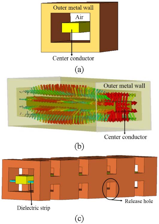
Fig. 1. Rectangular transmission line. (a) Basic model. (b) Electric filed distribution. (c) Fabricated model.
Figure 1 (b) presents the electric field distribution. The crucial problem that needs to be solved to realize the rectangular microcoaxial transmission line is how to suspend the center conductor in the metal wall. The development of surface micromachining technology enables the transmission line to be well realized and the form is depicted in Figure 1 (c). The center conductor is supported by periodically distributed dielectric strips, and release holes are added to the metal wall.
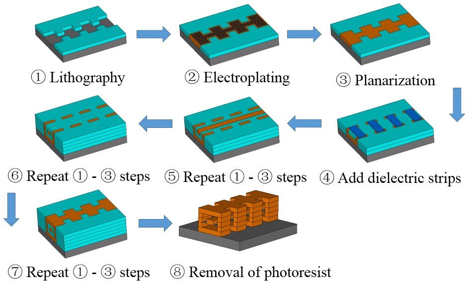
Fig. 2. Surface micromachining process.
The fabricated process of a section of rectangular microcoaxial transmission line based on surface micromachining technology is shown in Figure 2, as the following steps. The whole structure is built up layer by layer. Generally, the thickness of each layer is 50–100 um. First, the photoresist is coated on the silicon substrate as a sacrificial layer and lithographically formed into the desired shape of the structure. Then, the copper is electroplated to the gaps of the sacrificial layer to form the structural part, and the structural part is flattened by polishing. Next, dielectric strips are added to a certain layer and repeat  steps. Finally, an etching solution is used to remove the sacrificial layer to form the final rectangular microcoaxial structure. In particular, the position of the dielectric strip can be at the bottom, lower middle, or middle of the center conductor. When the dielectric strip is located in the lower middle or middle of the center conductor, the fabrication of the center conductor needs to be divided into more layers. Moreover, in order to remove the sacrificial layer cleanly, the outer wall of the transmission line is added to release holes. In the design of the T-junction power divider, the rectangular microcoaxial structure can be roughly divided into five layers, and the thickness of each layer is 100 um.
Figure 3 shows the simulated S-parameters of two transmission line models (basic model and fabricated model). With the addition of release holes and dielectric strips, S deteriorates slightly at low frequency, while it becomes better at high frequency. The S is basically unchanged. The surface current of a rectangular coaxial transmission line is presented in the Figure 4. Since the electric field intensity at the position of the release hole is relatively small, the size of the release hole does not have a significant influence on the transmission loss. However, as the width of the dielectric strip increases, the deterioration of S is obvious, which is depicted in the Figure 3. Therefore, in the design, the total volume occupied by the dielectric strips should be as small as possible.
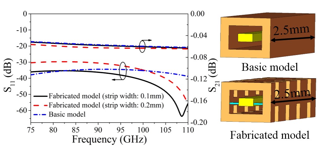
Fig. 3. Simulated S-parameters of two transmission line model.
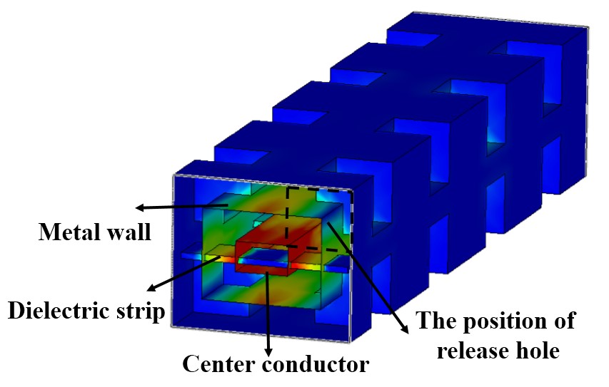
Fig. 4. The surface current of a rectangular coaxial transmission line.
The characteristic impedance of the rectangular coaxial line is related to the size of the air cavity and the center conductor. In order to simplify the design, we generally fix the dimension of the air cavity, and realize different characteristic impedances by changing the size of the inner conductor. The value of the height a is 100 um, which is determined by the processing technology. Therefore, the characteristic impedance of rectangular microcoaxial line is only related to the width b of the center conductor. And, the characteristic impedance decreases as b increases, which is presented in the Figure 5. Impedance transformation is the basis of RF circuit design.
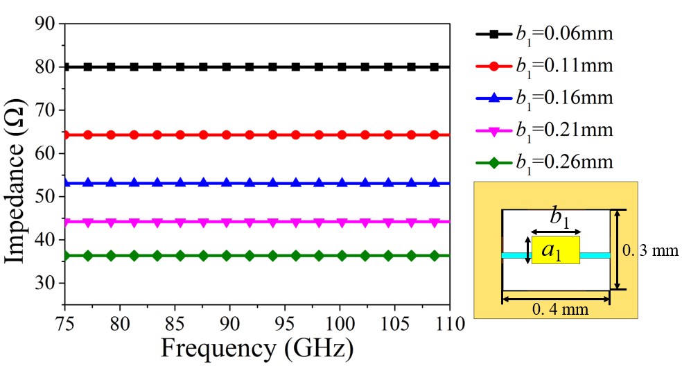
Fig. 5. Characteristic impedance versus b1.
In order to facilitate the test of the rectangular microcoaxial structure and the interconnection with the microwave monolithic integrated circuits, a rectangular coaxial line to coplanar waveguide (CPW) transition structure is designed. Figure 6 demonstrates a back-to-back transition. The design of the transition structure is as follows, the width of the center conductor gradually decreases, and the upper half of the outer metal wall is shaved off. The final width of the center conductor is 60 um, and its distance from the metal wall is 45 um. This design is based on the distance between the test probes.
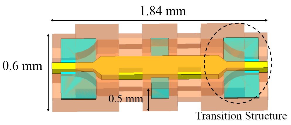
Fig. 6. The back-to-back transition of rectangular coaxial line to CPW.
The structure shown in the Figure 6 is fabricated to verify the performance of the transition structure. We use a W-band vector network analyzer with ground-signal-ground (GSG) probe to test the fabricated back-to-back transition structure, which is depicted in Figure 7 (a). The vector network analyzer is first connected to the frequency expansion module through cables, and then the expansion module is connected to the GSG probes. In the process of testing, the signal probe is connected to the center conductor, and the two ground probes are connected to the outer metal wall. The measurement is carried out using a standard SOLT calibration process. As shown in Figure 7 (b), compared with the simulation, the measured S is slightly worse, however, it still remains below –23 dB. In addition, the measured insertion loss is about 0.38 dB at high frequencies, which is 0.2 dB lager than the simulated result. Moreover, we analyze the influence on the insertion loss induced by the surface roughness. And, these analyses are based on the CST simulator, where the parameter r represents the root mean square roughness. When r is 0.6 um, the fitting result is the best, which implies that the roughness of the processing technology can be within 0.6 um.
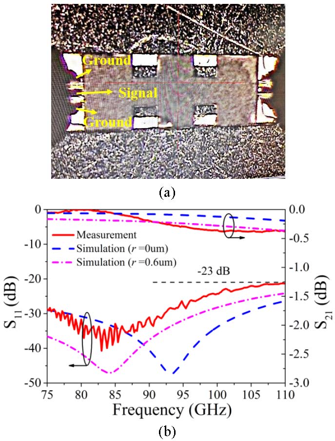
Fig. 7. Measurement of a back-to-back transition. (a) Test process. (b) Measured and simulated results.
III. DESIGN OF T-JUNCTION POWER DIVI DER
T-junction power divider is a traditional structure, and it can be realized by many forms, such as microstrips, waveguides, and SIWs.
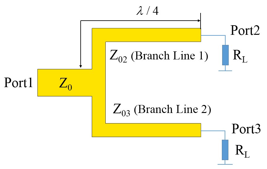
Fig. 8. Basic circuit of T-junction power divider.
The ideal power divider has the following characteristics. First, the amplitudes and phases of the two output ports are equal. Second, the output power ratio of port 2 and port 3 can meet any given value. Figure 8 presents the basic circuit, and we can get the equation about the value of relevant impedance based on /4 transmission line impedance transformation theory [16], as the following equations (1), (2).
| (1) |
| (2) |
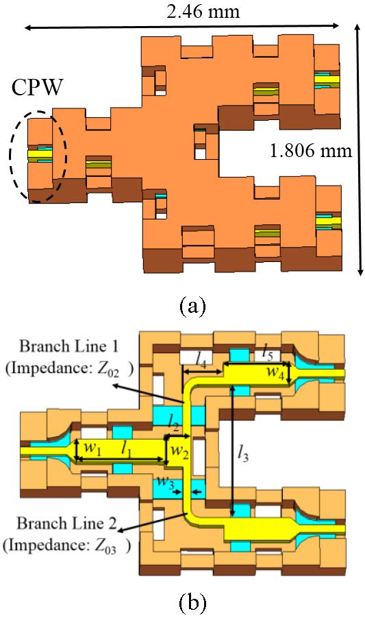
Fig. 9. The structure of the two-way power divider. (a) External structure. (b) Internal structure.
where K is the ratio of the output power of port 2 and port 3, expressed as P = KP. When the amplitudes of the output signals of port 2 and port 3 are the same, K is 1. We take Z as 50 , then Z and Z are both 70.7 . Combined with the analysis of the characteristic impedance of the rectangular coaxial transmission line, we can get the initial widths of the corresponding branch lines. The medium between the center conductor and the outer metal wall of the rectangular microcoaxial line is air, and the guided wavelength of the rectangular coaxial line is the same as the wavelength in the medium. According to the center frequency of the component, the initial lengths of the branch lines are obtained. After optimization by CST simulator, the structure of the two-way power divider is shown in Figure 9. The branch line 1 and the branch line 2 are connected by a square matching structure. The dimensions are labeled in Figure 9 (b), as follows (units: mm): l = 0.67, w = 0.176, l = 0.14, w = 0.25, l = 1.03, w = 0.06, l = 0.31, w = 0.176, and l = 0.5. Figure 10 illustrates the simulated results of the two-way power divider. The return loss of input port is above 17 dB and the insertion losses of two output ports are close to 3 dB from 75 to 110 GHz. The amplitude imbalance is kept within 0.03 dB. In addition, the isolation between the two output ports is about –6 dB. Since there is no isolation structure between the output ports, the isolation of this kind of power divider is generally not high. Moreover, due to the symmetric structure, the signals of the two output ports maintain nearly identical phase with a phase fluctuating between –0.015 and 0.1.
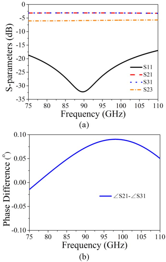
Fig. 10. Simulated results of two-way power divider. (a) S-parameter response. (b) Phase difference.
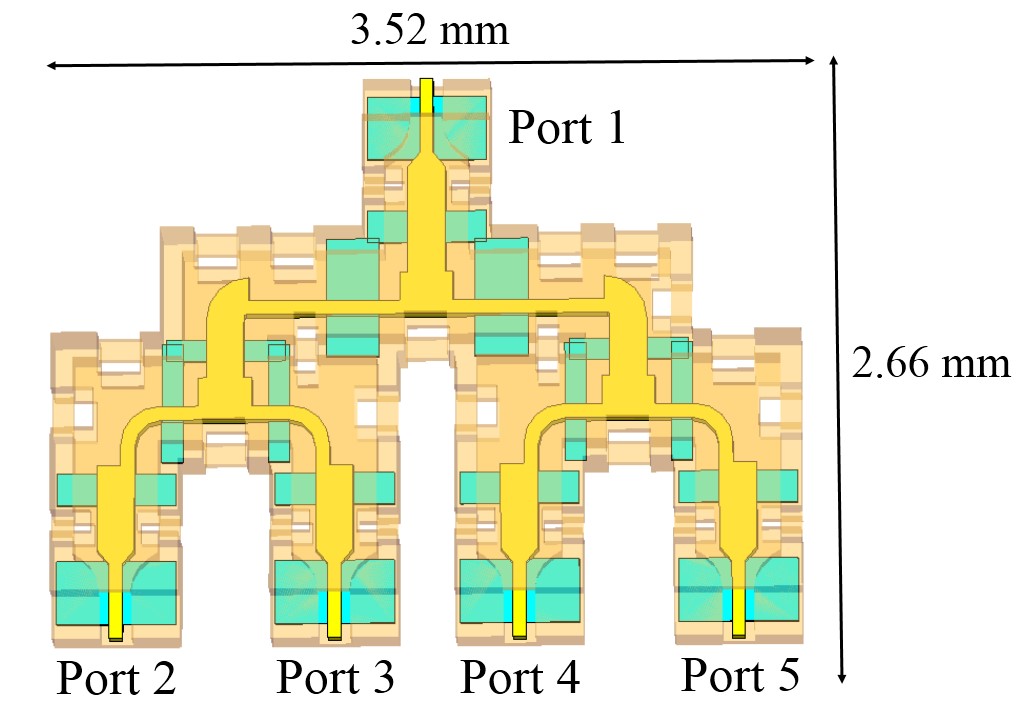
Fig. 11. The structure of four-way power divider.
Based on the analysis of two-way rectangular microcoaxial power divider, a four-way power divider is designed and presented in Figure 11. After optimization, the simulated results are shown in Figure 12. The return loss of port 1 is higher than 17 dB, and the insertion losses of output ports fluctuate between 6.05 dB and 6.4 dB. It can be seen from Figure 12 (b) that the phases of port 2, 3, 4, and 5 are in phase, and the phase imbalance is between –0.42 and 0.52.
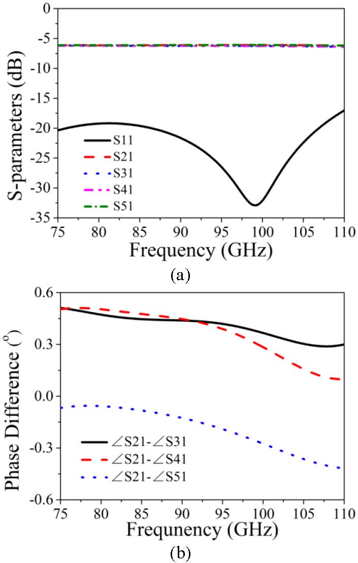
Fig. 12. Simulated results of four-way power divider. (a) S-parameter response. (b) Phase difference.
IV. EXPERIMENT AND DISCUSSION
In order to verify the effectiveness of the design, a prototype including two identical two-way rectangular microcoaxial power dividers arranged in a back-to-back configuration is fabricated based on the surface micromachining technology, as shown in Figure 13. And its overall size is 4.18 mm 1.89 mm 0.5 mm. The test method is the same as that of the back-to-back transition.
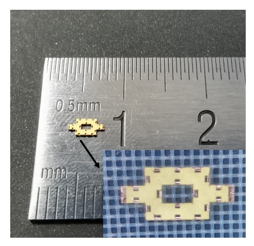
Fig. 13. Photograph of the fabricated prototype.
The simulated and measured results of the fabricated prototype are presented in Figure 14. The measured insertion loss fluctuates between 0.11 dB and 1.18 dB, which implies to a certain extent that the insertion loss of the proposed two-way power divider is from 0.055 dB to 0.59 dB over the W band. The tested S curve is basically consistent with the simulation, which illustrates the effectiveness of the design. Moreover, the measured S is less than -10 dB at 75-110 GHz and less than -20 dB at 75-93.3 GHz.
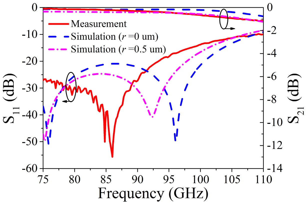
Fig. 14. Simulated and measured results of the fabricated prototype.
It can be found that the measured S response is quite different from the simulated one. The main reasons for the differences between the simulated results and the measured results include the fabrication errors and the measurement errors. Fabrication errors mainly include the surface roughness, unclean removal of photoresist and the inconsistency of the dimensions between the fabricated structure and the design model. The influence of surface roughness on insertion loss is analyzed. When r is 0.5 um, the fitting result of transmission loss is the best. The measurement errors mainly include the calibration of the measurement equipment and the contact position of the probe and the component. The contact position of the GSG probe and CPW affects the matching characteristic of the port. During testing, it is difficult to find the most suitable position.
Table 1 presents a comparison between the proposed power divider and some previous works. It can be found that the presented study has a small insertion loss while maintaining a compact structure.
Table 1: Comparison of some previous power dividers (back-to-back configuration)
| Reference | BW | IL | RL | Channel | Size |
| (GHz) | (dB) | (dB) | (mm) | ||
| 11 | 90.5–94.5 | 3.8–6 | 10 | 4 | not given |
| 7 | 90–96 | 2 | 20 | 14 | 80 80 54 |
| 17 | 75–110 | 0.8–2.6 | 14 | 4 | 75 50 19.1 |
| This work | 75–110 | 0.11–1.18 | 10 | 2 | 4.18 1.89 0.5 |
| BW: bandwidth, IL: insertion loss, RL: return loss. | |||||
V. CONCLUSION
In this paper, a two-way T-junction rectangular microcoaxial power divider is designed for W-band application, and the fabrication is based on surface micromachining technology. Meanwhile, the power divider can be expanded to more channels as requirement. The measured maximum insertion loss of the two-way power divider is about 0.59 dB over the entire W band, corresponding to a power-combining/splitting efficiency of 87.3%. The power divider is conductive to the W-band communication system with the compact structure and good performance.
REFERENCES
[1] Y. Jiang, Y. Ye, D. T. Li, Z. Y. Huang, C. Wang, J. J. Huang, and N. C. Yuan, “Design of W-band PIN diode SPDT switch with low loss,” Applied Computational Electromagnetics Society (ACES) Journal, vol. 36, no. 7, pp. 901-907, Jul. 2021.
[2] T. Huang, D. Jiang, and H. Z. Hu, “Wideband power divider using novel split-ring resonator,” Applied Computational Electromagnetics Society (ACES) Journal, vol. 30, no. 2, pp. 204-207, Feb. 2015.
[3] Y. L. Wu, J. C. Li, and Y. N. Liu, “A simple coupled-line wilkinson power divider for arbitrary complex input and output terminated impedances,” Applied Computational Electro-magnetics Society (ACES) Journal, vol. 29, no. 7, pp. 565-570, Jul. 2014.
[4] L. Li, J. X. Li, X. Y. Wei, and A. X. Zhang, “A W-band broadband power divider/combiner using two parallel antisymmetric tapered probes,” Int J RF Microw Comput Aided Eng., vol. 28, no. 1, pp. 1-9, Jan. 2017.
[5] Z. Y. Huang, Y. Jiang, J. J. Huang, W. D. Hu, and N. C. Yuan, “Flexible design of W-band bandpass filter with multiple transmission zeros,” Microw Opt Technol Lett., vol. 63, no. 9, pp. 2355-2358, Sep. 2021.
[6] Y. G. Li, Y. H. Zhang, G. D. Zhu, Z. Sun, and Y. Fan, “A W-band miniature power divider based on E-faced-folded magic-T junction,” 2016 IEEE MTT-S International Microwave Workshop Series on Advanced Materials and Processes for RF and THz Applications (IMWS-AMP), Chengdu, China, pp. 1-3, 2016.
[7] J. Zhan, M. Z. Zhan, and W. D. He, “W-band radial power combiner based on circularly polarized TE11 mode,” 2019 IEEE MTT-S International Wireless Symposium (IWS), Guangzhou, China, pp. 1-3, 2019.
[8] S. Y. Hu, K. J. Song, F. Zhang, Y. Zhu, and Y. Fan, “A novel compact wideband four-way W-band waveguide power divider with low insertion loss,” 2016 IEEE MTT-S International Microwave Workshop Series on Advanced Materials and Processes for RF and THz Applications (IMWS-AMP), Chengdu, China, pp. 1-3, 2016.
[9] T. X. Su, C. J. Yu, and M. H. Zhao, “W-band four-way E-plane waveguide power divider,” 2016 IEEE MTT-S International Microwave Workshop Series on Advanced Materials and Processes for RF and THz Applications (IMWS-AMP), Chengdu, China, pp. 1-3, 2016.
[10] L. J. Zhang and T. Liu, “A new H-plane T-junction waveguide power divider covering the full W-band,” 2020 IEEE 3rd International Conference on Electronic Information and Communication Technology (ICEICT), Shenzhen, China, pp. 803-805, 2020.
[11] J. Li, Y. J. Huang, and G. J. Wen, “W-band longitudinal-slot coupling four-way SIW power combiner /divider,” 2017 International Applied Computational Electromagnetics Society Symposium (ACES), Suzhou, China, pp. 1-2, 2017.
[12] Y. Li, P. L. Kirby, O. Offranc, and J. Papapolymerou, “Silicon micromachined W-band hybrid coupler and power divider using DRIE technique,” IEEE Microw. Wireless Compon. Lett., vol. 18, no. 1, pp. 22-24, Jan. 2008.
[13] E. R. Brown, A. L. Cohen, C. A. Bang, M. S. Lockard, B. W. Byrne, N. M. Vandelli, D. S. McPherson, and G. Zhang, “Characteristics of microfabricated rectangular coax in the Ka band,” Microw Opt Technol Lett., vol. 40, no. 5, pp. 365-368, Mar. 2004.
[14] N. A. Sutton and D. S. Filipovic, “Wideband micromachined broadside coupled Schiffman phase shifter,” Electron let., vol. 50, no. 6, pp. 454-U115, Mar. 2014.
[15] J. R. Reid, E. D. Marsh, and R. T. Webster, “Micromachined rectangular-coaxial transmission lines,” IEEE Trans Microw Theory Tech., vol. 54, no. 8, pp. 3433-3442, Aug. 2006.
[16] K. Chen, B. Yan, and R. M. Xu, “A novel W-band ultra-wideband substrate integrated waveguide (SIW) T-junction power divider,” 2010 International Symposium on Signals, Systems and Electronics, Nanjing, China, pp. 1-3, 2010.
[17] J. X. Li, L. Li, L. Lu, H. Y. Shi, H. H. Huo, and A. X. Zhang, “Four-way waveguide power divider design for W-band applications,” Int J RF Microw Comput Aided Eng., vol. 28, no. 5, pp. 1-5, Jun. 2018.
BIOGRAPHIES

Zhao-Yu Huang was born in 1992. He received the M.S. degree in Electronics and Communication Engineering from the University of Electronic Science and Technology of China, Chengdu, China in 2018. He is currently working toward Ph.D. degree with the College of Electronic Science and Technology, National University of Defense Technology, Changsha, China. His current research interests include passive RF/microwave circuits, microstrip antennas, and wireless communication.

Bo-Yuan Liu was born in 1991. He has received Master’s Degree from University of Electronic Science and Technology, China and currently working toward the Doctor’s Degree in National University of Defense Technology. His research interests are microwave and millimeter wave circuits and systems, Radar guidance, electronic countermeasures, and electromagnetic technology.

Yun Jiang was born in Hunan Province, China. He received the M.S. degree in electronics engineering from the University of Electronic Science and Technology of China (UESTC), Chengdu, China, in 2017, and currently he is working toward the Ph.D. degree in National University of Defense technology. His research interests include RF/millimeter-wave components and circuits.

Wen-Tao Yuan was born in 1990. He received his M.S. degree in Computer Science and Technology from the Anhui Normal University in 2016. Currently he is working towards the Ph.D. degree in the College of Electronic Science and Technology, National University of Defense Technology, Changsha, Hunan, China. His research interests include passive microwave circuits design and wireless communication.

Qing-Ping Wang was born in 1988. He received the Ph.D. degree from National University of Defense Technology. He is currently an associate researcher with the National University of Defense Technology. His research interests include automatic target recognition, microwave circuits and systems.

Wei-Dong Hu was born in 1967. He received the Ph.D. degree from National University of Defense Technology in 1997. He is currently a Professor with the National University of Defense Technology. His research interests include microwave and millimeter-wave circuits and systems and radar information processing.

Nai-Chang Yuan was born in Anhui, China, in 1965. He received the M.S. and Ph.D. degrees in electronic science and technology from the University of Electronic Science and Technology of China in 1991 and 1994, respectively. He is currently a Professor with the National University of Defense Technology. His research interests include microwave passive components, active components, antennas, microwave monolithic integrated circuits (MMICs), and RF integrated circuits (RFICs).
ACES JOURNAL, Vol. 36, No. 10, 1347–1354.
doi: 10.13052/2021.ACES.J.361011
© 2021 River Publishers