Slit-Loaded Hexagonal Patch for Body Area Network Applications at 5.8 GHz
Shaktijeet Mahapatra and Mihir Narayan Mohanty
ITER, Siksha O’ Anusandhan deemed to be University, Odisha, India
shaktijeetmahapatra@gmail.com, mihir.n.mohanty@gmail.com
Submitted On: July 27, 2021; Accepted On: September 15, 2021
Abstract
Increasing population and expanding remote healthcare monitoring needs have provided an impetus to the research and development of wireless devices. The quest for smaller antennas for wireless devices has led to the design of the proposed antenna. In this work, we present a slit-loaded hexagonal patch antenna for body area network applications. The antenna has been designed on a 0.193 FR4-epoxy substrate. The radiator patch has two parallel slits. The antenna resonates at 5.8 GHz (ISM band) with a wide bandwidth of 1.15 GHz. A maximum gain of 5.81 dB and a front-to-back ratio of 11.93 dB is observed at 5.8 GHz. Radiation efficiency is observed to be 72.3%. The measured return loss values show a close agreement with the simulated results. Specific absorption rate (SAR) analysis on a simplified 2/3 muscle model shows an average SAR of 0.5633 W kg, due to the use of a full-ground plane. The simulations were done in ANSYS HFSS. The antenna is suitable for on-body communications.
Index Terms: hexagonal patch, inset-fed, ISM band, miniature, slit-loaded.
I. INTRODUCTION
Antennas are the reason that the market for wireless communication devices thrives. A device without an antenna cannot communicate with other devices on a physical level. Antennas are not only responsible for launching or receiving the electromagnetic waves into the space but also for filtering and providing the passive gains to the signals. The antennas have to be designed carefully to meet the requirements of the communication system they are part of.
With the increase in the number of wireless handheld devices for day-to-day monitoring for health, security, business, and military purposes, the need to connect to data-collecting devices has also risen [1, 2]. Therefore, the requirement for antennas that can be easily integrated with such devices has also risen. However, the design of antennas for portable devices has its own set of challenges. The antenna needs to be small and yet operate at ISM bands. The specific absorption rate (SAR) should remain within safe limits to avoid unnecessary heating of the tissues. The bandwidth should be wide enough to resist interference from other devices and the detuning effect of proximity to the body. Due to the less area available for the antenna, the antenna geometry, the feeding technique, and the corresponding matching technique have to be chosen carefully.
In this paper, we propose a miniaturized hexagonal microstrip patch radiator. The choice of hexagonal shape was driven by the fact that it offers longer electrical path length, and slightly better bandwidths and gains than rectangular or circular shaped radiators. The hexagonal shape also utilizes available areas more efficiently than rectangular and circular patches. The radiator has two parallel slits which bring down the resonant frequency to include the 5.8 GHz ISM band. The slits are the cuts made from the edges, and when placed close to the feed point, load the antenna with the capacitance [3]. Both the slots and the slits have been used to increase the bandwidth and lower the resonant frequency [4]. The choice of this band is motivated by the fact that the band at 2.45 GHz is already congested, and the 5.8 GHz band is relatively free and can support higher data rates [5]. The ground plane has a small circular slot for enhancing the bandwidth of the antenna. The antenna is fed through one of the edges by a microstrip line at an inset. The inset feeding helps in matching the port impedance with the input impedance of the antenna. This technique is very easy to implement and does not demand extra area outside the patch [6]. Feeding through the edge ensures better isolation between the antenna and the subject. The antenna offers very wide bandwidth and a moderate gain. SAR of the antenna is also well within limits. The antenna has been simulated using the ANSYS HFSS platform.
In the subsequent sections, some of the related works, antenna design, and results are presented and discussed. The conclusion section summarizes the work in this paper and the referred works are cited in the reference section.
II. RELATED WORKS
Antennas designed for wearable purposes should not only be compact but also have smaller back lobes. Smaller back lobes mean lesser exposure of living tissue to the electromagnetic radiations, and hence lower SARs.
A metamaterial-based superstrate for enhancing gain by 12 dBi and bandwidth by 355 MHz at 5.8 GHz in [7]. A 22 element patch antenna array for unmanned aerial vehicles on a PCB substrate and a gain of 6.2 dB was obtained in [8]. designed A lightweight and optically transparent antenna using VeilShield for conducting parts and polydimethylsiloxane (PDMS) operating at 5.8 GHz was designed in [9] and a gain of 3.35 dB was reported. In [10], an antenna loaded with an artificial magnetic conductor working at 5.8 GHz for ingestible endoscopy on polyimide was designed and a gain of 1.64 dBi was reported. A MIMO antenna at 5.8 GHz with a metasurface structure for enhancing gain was designed in [11]. A dual-band antenna with electromagnetic bandgap (EBG) structure on F4B substrate was used in [12] with a gain of 9.1 dBi at 5.8 GHz. A high-gain hexagonal patch antenna for V2V communication was designed in [13]. Slot-loaded hexagonal microstrip antenna designed on FR4 by [14] operated in multiple bands. A button antenna for WBAN applications covering 2.45 and 5.8 GHz with dual-polarization by [15]. A patch antenna array designed in [16], was loaded with split ring resonators and via holes resulting in dual-band operations. Nitinol-strip–based reconfigurable fractal antenna using artificial neural network was designed in [17] that operated in 2.4 GHz and 5.2 GHz bands and four configurable modes. Antennas for wearable applications with wide bandwidth and low SAR are presented in [18, 19].
From the above literature, we find that the hexagonal antennas have not been explored for body area network. In this work, we emphasize on the reduced size that can perform better as compared to earlier designs in terms of the gain and the bandwidth. Therefore, the design is proposed and explained in the following sections. It also performs well for the SAR reduction. Finally, the comparative results are exhibited in result section.
III. ANTENNA DESIGN
The antenna has been designed on an FR4-epoxy substrate measuring 10 10 1.6 mm. Mechanical strength, suitable RF response, resistance to humidity and temperature, and easy availability were important factors in deciding the substrate. The dielectric constant of FR4 remains fairly close to 4.35 even up to 7 GHz [20].
The radiator patch is hexagonal. The hexagon-shaped patches have better area utilization than rectangular or circular patches. Moreover, they provide a longer radiating edge and hence can be easily used for lower frequencies. For the computation of resonant frequency for any TM mode for a hexagonal patch with a side a, an empirical equation has been developed by curve fitting the theoretical and experimental results. The equation uses an effective value of side length a, to compute the resonant frequency. As a regular hexagon can be equally divided into equilateral triangles, therefore starting equations are modified versions of those used for equilateral triangular patches [21].
| (1) |
where a is empirically given by
| (2) |
For 5.8 GHz and TM10 mode, a hexagonal patch of side length 15.48 mm is required. As the objective of this work is to design a miniaturized antenna, a patch with a side of 4.5 mm is chosen.
In order to meet the objective of the resonant frequency, we need to increase the capacitance of the patch antenna by increasing the electrical path length. This can be done by introducing a slit in the patch [3]. Two slits were introduced to bring down the resonant frequency to 5.8 GHz. The increase of path length produced by two slits together is larger than one slit. This allowed for the miniaturization of the antenna.
For maximum power transfer from the port to the antenna, the return loss has to be reduced. To reduce the return loss at the same frequency, we have to increase the degree of matching between the port and the antenna. The easiest method to do this is to use the inset feed technique. This introduces matching impedance. On both sides of the feedline, a gap of 0.35 mm is introduced. The feedline intersects the patch at 1.5 mm from the edge. A longer feedline introduces inductive impedance and the gaps introduce capacitive impedance. This transforms the input impedance of the patch to the characteristic impedance of the lumped port.
For the computation of the input impedance, we approximate the hexagon to the circumscribing circle of radius, r. If the side of a hexagon is a, then r = a. The effective radius, r, of the assumed circumscribing circle can be expressed as [23]:
| (3) |
The input impedance, Z of the assumed circular disk circumscribing the hexagonal patch is the load impedance for (4). Z at any radial distance = 0 for TM11 mode for a circular disk is given by [22]
| (4) |
where k is the wavenumber, J(x) is the Bessel’s function of the first kind of order 1, and G is the total conductance. The total conductance, G is given by
| (5) |
The conductance between the patch and the full ground plane, G is given by:
| (6) |
The ohmic conductance that accounts for the ohmic loss, G is given by
| (7) |
The losses in dielectric are accounted by G, given by:
| (8) |
where = 2 for m = 0, = 1 for other m, and f is the resonant frequency of the mn0 mode.
The dependence of Q factor, Q on bandwidth, BW is given by [23]:
| (9) |
where Q is given by
| (10) |
and I is an integral given by,
| (11) |
To enhance the bandwidth of the antenna, we have to reduce the Q-factor of the antenna slightly. For this, we introduce a circular slot of 1 mm diameter in the ground plane.
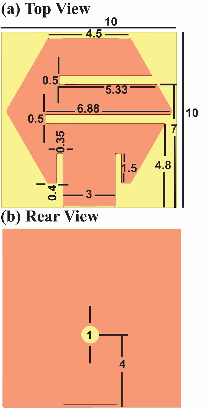
Fig. 1. Front and rear view of the proposed antenna (All dimensions are in mm).
The finalized design and dimensions of the antenna are shown in Figure 1.
Design steps
1. On a substrate measuring 10 10 1.6 mm, a hexagon-shaped patch of copper is created. Each side of the patch measures 4.5 mm.
2. A microstrip feed line of 3 mm is provided at one of the edges of the patch.
3. A lumped port with a characteristic impedance of 50? is assigned at the other end of the microstrip feed line.
4. Slits, 0.5 mm wide, are cut from the patch.
5. Slits, 0.35 mm wide and 1.5 mm in length, are cut on both sides of the feed line in the patch.
6. A circular slot of 1 mm diameter is cut from the ground plane for enhancing the bandwidth.
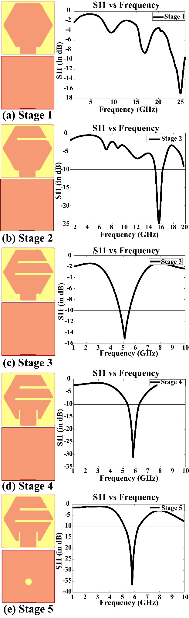
Fig. 2. Design stages of the antenna.
IV. RESULTS AND DISCUSSIONS
The objective of this paper is to design a miniature antenna for body area network applications working at 5.8 GHz, with an impedance bandwidth of more than 1 GHz.
We start with the hexagonal patch with a side of 4.5 mm. The antenna in stage 1 in Figure 2 (a) has the resonant frequency occurring at 24.9 GHz. In stage 2, the first slit is introduced as shown in Figure 2 (b). Due to the increased capacitance, the resonant frequency of the stage 2 antenna comes down to 15.6 GHz. However, to further reduce the resonant frequency close to the band of interest, we introduce the second slit closer to the feed. From the return loss of antenna of stage 3 shown in Figure 2 (c), it can be seen that the resonant frequency (5.1 GHz) comes close to the required frequency, 5.8 GHz. The return loss is –15 dB. For better performance, the matching with the port should be improved. For improving the match, the inset feeding technique is used. The resulting antenna in stage 4 now resonates at 5.8 GHz with an improved return loss of –31.15 dB as can be seen from Figure 2 (d). To further enhance the bandwidth and the gain of the antenna, a circular slot is introduced in the ground plane near the feed point of the patch. The resulting antenna of stage 5 and its corresponding return loss plot is shown in Figure 2 (e). A comparison of gains of antennas of stage 4 and stage 5 is given in Figure 3. The addition of the slot in the ground plane increased the gain by at least 4 dB in the broadside direction. It is also observed that the back lobes also reduce considerably.
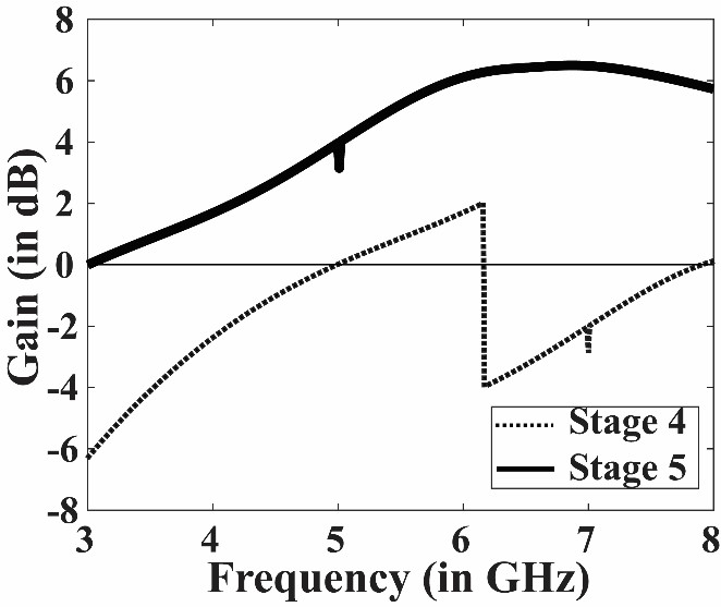
Fig. 3. Gain vs frequency plot of antenna in stage 4 and stage 5.
The antenna of stage 5 was finalized as it met our requirements and the antenna was fabricated. The fabricated antenna is shown in Figure 4. Figure 5 shows S11 or reflection coefficient plots of the simulated and the fabricated versions. The return loss at 5.8 GHz for the simulated design is –36.5 dB and for the fabricated antenna is –31.23 dB. This frequency is considered for body area network communications. The antenna covers the ISM band and is capable of handling high data rate communications. The bandwidth of the simulated design is observed to be 1.17 GHz and that of the fabricated one is found to be 1.06 GHz.

Fig. 4. Fabricated antenna.
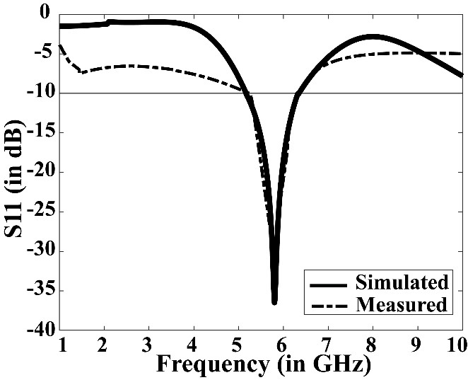
Fig. 5. A comparison of return loss characteristics of the simulated and fabricated versions.
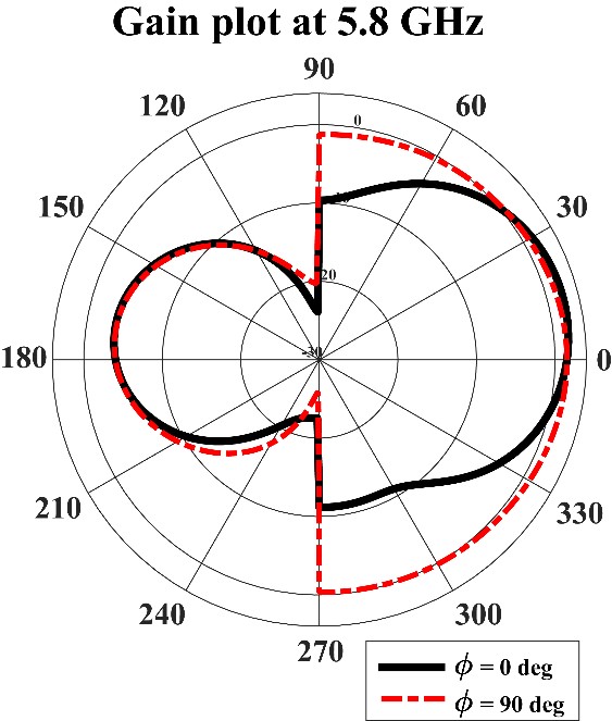
Fig. 6. Gain plot of the proposed antenna.
Figure 6 shows the gain of the antenna in directions at phi equal to 0 and 90 degrees, corresponding to H-plane and E-plane respectively. It can be observed seen that in the broadside direction, the gain is 5.81 dB. It can also be observed that due to the ground plane the back radiation has been reduced. A high gain is one of most characteristics for an antenna designed for wearable purposes as it compensates for various losses to some extent. The front-to-back ratio (FBR) can be computed from the gain plot by taking the ratio of maximum gain to the gain in opposite direction. FBR, in dB = maximum gain (dB) – gain in exactly opposite direction (dB). The maximum gain is 5.81 dB and the gain in the opposite direction is –6.12 dB. Thus, the FBR is 11.93 dB. This is an important result as it shows how much of the radiation is in the forward direction. This gives the idea of radiation being directed away from the human body. The radiation efficiency was found to be 72.3% as a result of better matching.
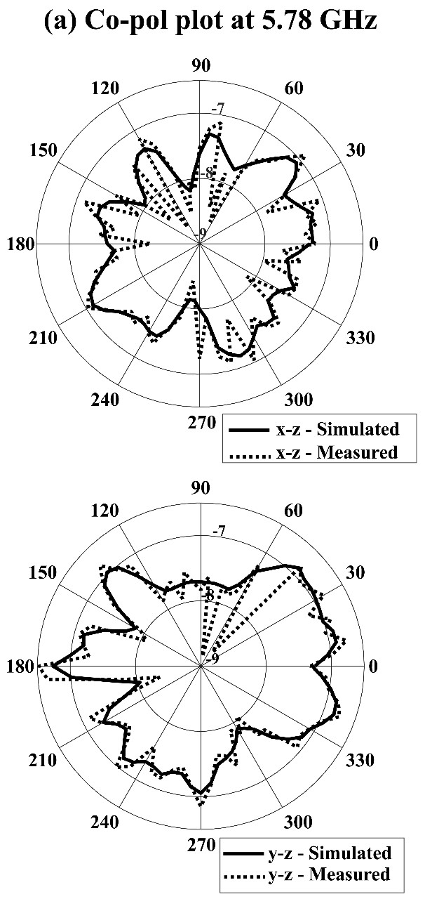

Fig. 7. Radiation pattern plots at 5.8 GHz.
Table 1: Summary of results
| Parameters | Simulated | Measured |
| Freq [GHz] | 5.8 | 5.8 |
| S11 [dB] | –36.5 | –31.25 |
| Bandwidth ( –10 dB) | 1.17 | 1.06 |
| Peak Gain [dB] | 5.8 | |
| Radiation Efficiency [%] | 72.3 | |
| Front-to-Back Ratio | 11.92 |
Figure 7 presents the radiation pattern in the E-plane and H-plane of the antenna measured at 5.8 GHz, with 10 dBm input power. Figure 8 (a) shows the electric field distribution and 8(b) shows the surface current distribution at 5.8 GHz. It can be observed that the slits disturbed the surface current distribution resulting in better bandwidth. A high value of the electric field can be observed near the slits. This indicates a better power transfer toward the radiating edges and a reason for the better efficiency of the antenna. Table 1 summarizes the findings of this work.
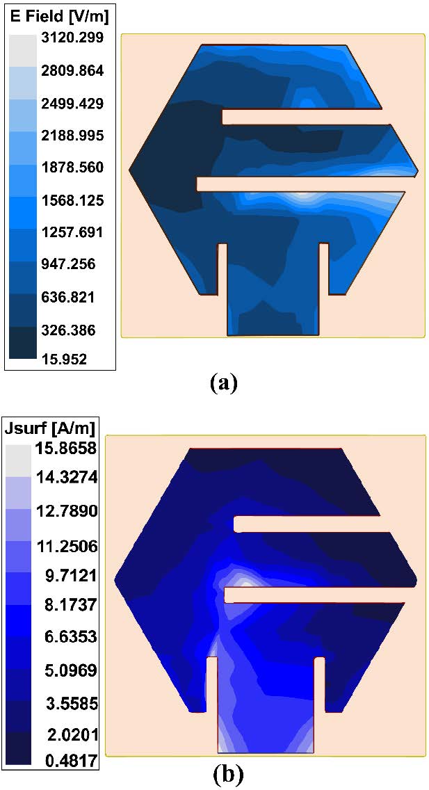
Fig. 8. (a) Electric field distribution; (b) Surface current distribution.
Figure 9 shows the simulated evaluation of the antenna to find the SAR. The antenna was evaluated on a simplified 4-layer 2/3 muscle model. In the 2/3 muscle model, the muscle occupies 2/3 of the volume of the tissue. Such tissues are mostly found on arms and thighs. These areas are generally where the wireless devices for off-body communication are usually placed. Skin, fat, muscle, and bone constitute the layers of the model and each layer acts as frequency-dependent lossy dielectrics. The dielectric constants (()) and loss tangents of the layers were computed at 5.8 GHz using following equations and given in Table 2 [24]:
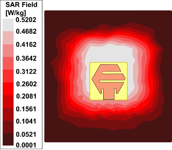
Fig. 9. Evaluation of SAR at 5.8 GHz.
| (12) |
| (13) |
The antenna was placed on the model and simulated results were observed. The living tissues absorb electromagnetic waves and heat up. SAR represents the degree of heating produced by electromagnetic waves emitted by the antenna. The threshold value of SAR is 1.6 W kg [25]. The SAR value of the antenna was observed to be 0.5633 W kg. This further makes the antenna suitable for body area network applications. A comparison with some previous works has been presented in Table 3.
Table 2: Dielectric constants and loss tangents of various layers at 5.8 GHz
| Layers | Skin | Fat | Muscle | Bone |
| Dielectric | 36.9549 | 5.0905 | 51.7447 | 10.3329 |
| constant | ||||
| Loss Tangent | 0.3281 | 0.2592 | 0.3516 | 0.3723 |
Table 3: Performance comparison with some previous works
| Ref. | Antenna/ Substrate | Antenna Structure Dimensions [mm] | Frequency [GHz]/ Gain [dB]/ SAR[W kg] |
| [10] | AMC-loaded radiator/ Polyimide | 4.6 7.6 0.15 | 5.8/1.64/0.82505 |
| [11] | MIMO antenna with a dipole, J-shaped balun, and metasurface/ RT5880 | 140 3.7 35.075 | 5.8/9.5/NA |
| [12] | Monopole with EBG/F4B | 67.71 64.71 10 | 5.8/9.1/0.212 |
| [14] | Slotted hexagonal patch/FR4 | 35 30 | 2.4/1.63; 5.03/1.38; 8.67/2.95; |
| [15] | Button antenna/Rogers RT 6006 | Radius 9.4 mm and 1.27 mm thickness | 2.45/2.2/1.04 5.8/8.6/0.29 |
| [16] | Array of patch loaded with SRR and via-holes/ FR4 | 7.5 cm 7.5 cm 1.48 mm | 2.45/5.6 5.0/11.4 |
| [17] | Fractal antenna/ Nitinol-strip | 3000 sq m | 2.5/22; 5.5/–6.99 |
| This Work | Inset-fed hexagonal patch with slits | 10 10 1.6 | 5.8/5.81/0.5633 |
V. CONCLUSIONS
In this work, a miniaturized hexagonal patch antenna is proposed. The miniaturization was possible due to two slits. The gain enhancement was done by a circular slot on the ground plane. The antenna is fed by a microstrip line at an inset and produced better matching results. The antenna operated in the frequency range 5.12–6.34 GHz and resonated at 5.8 GHz. The measured value of the antenna agrees closely with the simulated results. The gain was observed to be 5.81 dB and the front-to-back ratio to be 11.92 dB at 5.8 GHz. The SAR analysis yielded an average SAR of 0.5633 W kg. These characteristics make the antenna suitable for body area communications at high data rates.
REFERENCES
[1] A. Y. I. Ashyap, S. H. B. Dahlan, Z. Z. Abidin, M. I. Abbasi, M. R. Kamarudin, H. A. Majid, M. H. Dahri, M. H. Jamaluddin, and A. Alomainy, “An overview of electromagnetic band-gap integrated wearable antennas,” IEEE Access, vol. 8, pp. 7641-7658, Jan. 2020. doi: 10.1109/ACCESS.2020.2963997.
[2] S. Mahapatra and M. N. Mohanty, “A review on state-of-art techniques of antennas for body area networks,” Int. J. Sensors, Wirel. Commun. Control, vol. 11, no. 6, pp. 604-618, Jul. 2021. doi: 10.2174/2210327910999201228152543.
[3] K. Siakavara, “Methods to design microstrip antennas for modern applications,” in Microstrip Antennas, N. Nasimuddin, Ed. InTech, pp. 173-236, 2011.
[4] S. Mahapatra and M. N. Mohanty, “Investigation on effects of slotting in a microstrip-fed rectangular patch antenna,” in 2018 2nd International Conference on Data Science and Business Analytics (ICDSBA), pp. 241-244, Dec. 2018.
[5] S. K. Behera and N. C. Karmakar, “Wearable chipless radio-frequency identification tags for biomedical applications: A Review [Antenna Applications Corner],” IEEE Antennas Propag. Mag., vol. 62, no. 3, pp. 94-104, Jun. 2020. doi: 10.1109/MAP.2020.2983978.
[6] S. Mahapatra and M. N. Mohanty, “Simulation and feed analysis of microstrip antenna for UWB communication,” in IEEE Conf. ICCPCT, pp. 18-20, Mar. 2014.
[7] C. Arora, S. Pattnaik, and R. Baral, “Performance enhancement of patch antenna array for 5.8 GHz Wi-MAX applications using metamaterial inspired technique,” AEU-International J. Electron. Commun., vol. 79, pp. 124-131, May 2017.
[8] N. Majidi, G. G. Yaralioglu, M. R. Sobhani, and T. Imeci, “Design of a quad element patch antenna at 5.8 GHz,” 2018 Int. Appl. Comput. Electromagn. Soc. Symp. Denver, ACES-Denver 2018, pp. 1-2, Mar. 2018. doi: 10.23919/ROPACES.2018.8364309.
[9] A. S. Sayem and K. P. Esselle, “A unique, compact, lightweight, flexible and unobtrusive Antenna for the Applications in Wireless Body Area Networks,” in 2019 13th International Conference on Signal Processing and Communication Systems (ICSPCS), pp. 1-4, Dec. 2019.
[10] T. M. Neebha, M. Nesasudha, and D. K. Janapala, “A stable miniaturised AMC loaded flexible monopole antenna for ingestible applications,” Comput. Biol. Med., vol. 116, p. 103578, Jan. 2020. doi: 10.1016/j.compbiomed.2019.103578.
[11] L. N. Nguyen, “A MIMO antenna with enhanced gain using metasurface,” Appl. Comput. Electromagn. Soc. J., vol. 36, no. 4, pp. 458-464, Apr. 2021. doi: 10.47037/2020.ACES.J.360412.
[12] C. Wang, L. Zhang, S. Wu, S. Huang, C. Liu, and X. Wu, “A Dual-band monopole antenna with ebg for wearable wireless body area networks,” Appl. Comput. Electromagn. Soc. J., vol. 36, no. 1, pp. 48-54, Jan. 2021. doi: 10.47037/2020.ACES.J.360107.
[13] H. Singhal, S. Ashwin, V. Sharma, J. Prajapati, and M. D. Upadhayay, “High gain hexagonal patch antenna for V2V communication,” 2020 7th Int. Conf. Signal Process. Integr. Networks, SPIN 2020, pp. 687-691, Feb. 2020. doi: 10.1109/SPIN48934.2020.9071270.
[14] A. O. Fadamiro, J. D. Ntawangaheza, O. J. Famoriji, Z. Zhang, and F. Lin, “Design of a multiband hexagonal patch antenna for wireless communication systems,” IETE J. Res., pp. 1-8, Oct. 2019. doi: 10.1080/03772063.2019.1664340.
[15] X. Yin, S. J. Chen, and C. Fumeaux, “Wearable dual-band dual-polarization button antenna for WBAN applications,” IEEE Antennas Wirel. Propag. Lett., vol. 19, no. 12, pp. 2240-2244, Oct. 2020. doi: 10.1109/LAWP.2020.3028868.
[16] C. Arora, S. S. Pattnaik, and R. N. Baral, “Dual band microstrip patch antenna array loaded with split ring resonators and via holes,” AEU - Int. J. Electron. Commun., vol. 93, no. June, pp. 253-260, Sep. 2018. doi: 10.1016/j.aeue.2018.06.016.
[17] S. Ambigapathy and J. Paramasivam, “2.4 GHz and 5.2 GHz frequency bands reconfigurable fractal antenna for wearable devices using ANN,” Appl. Comput. Electromagn. Soc. J., vol. 36, no. 3, pp. 354-362, Mar. 2021. doi: 10.47037/2020.ACES.J.360315.
[18] S. Mahapatra, L. P. Mishra, and M. N. Mohanty, “Design of circular patch antenna with modified ground structure for body area communication,” in 2020 International Conference on Communication and Signal Processing (ICCSP), pp. 512-514, Jul. 2020.
[19] S. Mahapatra, J. Mishra, and M. Dey, “A dual-band inset-fed octagonal patch antenna for wearable applications,” in Advances in Intelligent Computing and Communication, Springer, pp. 699-706, May 2021.
[20] J. Paleèek, M. Vestenick, P. Vestenick, and J. Spalek, “Frequency dependence examination of PCB material FR4 relative permittivity,” IFAC Proc. Vol., vol. 46, no. 28 Part 1, pp. 90-94, Jan. 2013. doi: 10.3182/20130925-3-CZ-3023.00020.
[21] K. Guney, “Input impedance of an equilateral triangular microstrip antenna,” Mediterr. Electrotech. Conf. - MELECON, vol. 2, no. 5, pp. 414-417, Apr. 1994. doi: 10.1109/melcon.1994.381070.
[22] C. A. Balanis, Antenna Theory - Analysis and Design, 3rd Edition. John Wiley and Sons, 2005.
[23] R. Garg, P. Bhartia, I. Bahl, and A. Ittipiboon, Microstrip Antenna Design Handbook. Artech House, 2001.
[24] P. S. Hall and Y. Hao, Antennas and Propagation for Body-Centric Wireless Communications. Artech House, 2012.
[25] IEEE_SCC39, IEEE Standard for Safety Levels with Respect to Human Exposure to Electric, Magnetic, and Electromagnetic Fields, 0 Hz to 300 GHz - Corrigenda 2, vol. 2019, 2020.
BIOGRAPHIES

Shaktijeet Mahapatra is currently working as an assistant professor in the Department of Electronics and Communication Engineering, Institute of Technical Education and Research (FET), Siksha ‘O’ Anusandhan (Deemed to be University), Bhubaneswar, Odisha. He received his M. Tech. degree in VLSI and Embedded System from the Biju Patnaik University of Technology, Odisha. He is currently pursuing his Ph.D. degree from Siksha ‘O’ Anusandhan (deemed to be University). His research interests include Antenna Design and IoT.

Mihir Narayan Mohanty is currently working as a Professor in the Department of Electronics and Communication Engineering, Institute of Technical Education and Research (FET), Siksha ‘O’ Anusandhan (Deemed to be University), Bhubaneswar, Odisha. He received his Ph.D. degree in Applied Signal Processing from the Biju Patnaik University of Technology, Odisha and his M. Tech. degree in Communication System Engineering from the Sambalpur University, Sambalpur, Odisha. He is the fellow of IE (I), and IETE. He is a senior member of IEEE and member of many professional societies including IET, ACES etc. He has more than 25 years of teaching and research experience. He has published more than 500 papers in different Journals, Conferences including Book Chapters. He has authored two books and edited two conference proceedings. He is the successive reviewer of manuscripts from IEEE, Elsevier, Springer, IGI Global, etc. His areas of research interests include Applied Signal and Image Processing, Wireless Communication, Antenna, and Intelligent Signal Processing.
ACES JOURNAL, Vol. 36, No. 11, 1429–1437.
doi: 10.13052/2021.ACES.J.361106
© 2021 River Publishers