Dynamic Characteristics Analysis of Magnetic Levitation Rotor Considering Unbalanced Magnetic Pull
Shuyue Zhang, Zaibin Chen, Xiaolian Lv, Hongli Yan, Jihao Wu and Yuanliang Zhou
1School of Mechanical and Electrical Engineering, Chuzhou University, Chuzhou 239000, China
shuyue_zhang@126.com, zhouyl2014@mail.dlut.edu.cn
2State Key Laboratory of Technologies in Space Cryogenic Propellants, Technical Institute of Physics and Chemistry, Chinese Academy of Sciences, Beijing, 100190, China
3University of Chinese Academy of Sciences, Beijing, 100190, China
Submitted On: October 18, 2021; Accepted On: October 12, 2022
ABSTRACT
The working principle of the motor can cause unbalanced magnetic pull (UMP) between stator and rotor unavoidably. Previous research about nonlinear vibration excited by UMP was focused on the rotor supported by traditional mechanical bearings or gas bearings. However, the magnetic levitation rotor is particular due to the low rigidity provided by the active magnetic bearing (AMB). UMP amplifies rotor vibration in the resonant zone and further excites the nonlinear electromagnetic force, thus producing different vibration phenomena. The paper calculates rotor orbit, spectra analysis, and time-history plot with numerical methods and studies the influence of the rotation speed, eccentricity, key control parameters, and UMP on rotor dynamics in detail. Results illustrate displacement response spectra of the magnetic levitation rotor are quite different from previous research results. The appearing frequency components are inducted by universal formulas in this paper. Furthermore, research shows a slight adjustment of the control parameters affect significantly harmonic components and vibration characteristics. The research results have practical reference significance for fault diagnosis, feature recognition, and controller optimization of the AMB-rotor system.
Index Terms: frequency response, magnetic levitation rotor, resonance, rotor orbit, unbalanced magnetic pull, vibration.
I. INTRODUCTION
Active magnetic bearings (AMBs) have the advantages of no wear, high rotation speed, and long life, and they can adjust rotor dynamics by active controlling [1]. Thus, AMBs show incredibly high usage potential in rotating machinery [2, 3]. However, AMBs have the supporting characteristics of ’negative stiffness’, and their electromagnetic forces are nonlinear. Stability and nonlinearity have been continuously researchedhotpots.
Magnetic levitation rotating machinery is generally driven by a motor. The air gap between the motor’s stator and its rotor is unavoidably uniform and asymmetric, resulting in the unbalanced magnetic pull (UMP) [4]. UMP leads to unwanted vibrations, causes stability problems, and even produces rubbing between the rotor and the stator [5].
UMP has attracted widespread attention from researchers. Establishing the linear relationship between UMP and eccentricity is convenient for calculating rotor dynamics [6, 7], but the relationship is reliable only when the eccentricity is small enough. Belmans et al. proposed the air gap permeability method to calculate the magnetic flux density for UMP’s analytical formula [8]. Later on, many researchers applied Belmans’s results to determine the nonlinear UMP.
Guo Dan et al. [9] established the UMP’s analytical formula and summarized the vibration characteristics of the ordinary rotor considering UMP. Xu Xueping et al. investigated how the static eccentricity UMP and gravity affect the rotor’s vibration excited by only dynamic eccentricity UMP [10, 11]. Results concluded that the rotor system’s static load has the same influence on rotor dynamics as the static eccentric UMP. Xu also derived the UMP force of a tilting rotor and studied the rotor’s motion behavior in the case [12]. Hui Lui et al. [13] employed a multi-scale perturbation method to obtain the natural frequency and frequency response characteristics of the rub-impact rotor-bearing system considering UMP. Li Hao et al. [14] analyzed the UMP’s influence on the rotor system supported by gas bearings. In [15], the UMP’s nonlinear effects on a colliding rotor for hydro-generator units were investigated by numeral calculations.
Rotor dynamics excited by UMP have been extensively investigated in the above literature, but most of them focus on traditional mechanical bearings or gas bearings. Relatively few studies pay attention to the coupling interaction between the AMB force and UMP. Du Tingshen et al. determined the UMP by the analytical method, and they applied numerical calculation software to verify [16]. Ji Li et al. studied the effects of various eccentricities and different loads on the UMP amplitude and phase [17]. Di Chong compared the UMPs with different eccentricities and proposed the structure optimization scheme of AMB to compensate for UMP [18]. The studies mentioned above did involve the UMP exerting on the magnetic levitation rotor; however, they didn’t thoroughly discuss how UMP affects the dynamic characteristics, especially the motion behavior when the rotor is passing through criticalspeeds.
The stiffness of the AMB-rotor system is relatively small. The rotor generally needs to cross rigid body mode frequency before reaching the rated speed, which is different from the rotor system supported by mechanical bearings and gas bearings. The rotor vibrates intensely when near critical speeds. On this occasion, it tends to vibrate more wildly and more complicated if the UMP is increasing to a certain extent, inevitably causing the AMB to work in a nonlinear region. Additionally, unlike mechanical bearings and gas bearings, the supporting properties of the AMBs depend more on the control algorithms and control parameters rather than their physical structure [19]. Regardless offault detection, state maintenance, or AMB controller design, investigating the rotor’s dynamic behavior under UMP is essential.
Therefore, this paper established the rotor system’s motion differential equation incorporating nonlinear AMB force, nonlinear UMP, and unbalanced mass excitation force. The rotor system’s dynamic behavior with different speeds, mass eccentricity, control parameters, and UMP are discussed in detail with numerical methods.
II. MODEL
A. Nonlinear AMB force
Figure 1 is the schematic diagram of the AMB-rotor system. The radial AMB has eight magnetic poles in all. The AMB force generated by the two pairs of magnets in one single degree of freedom (DOF) can be expressed as follows [1]:
| (1) |
where vacuum permeability =410 N/A denotes the number of coil turns, A denotes the area of magnetic poles, denotes the angle between two adjacent magnetic poles, t denotes the time variable, s denotes the static equilibrium position, s denotes the displacement of the offset equilibrium position, i denotes the bias current, i denotes the control current controlling the rotor back to the equilibrium position (i+ i(t)), and (i – i(t)) represent the total current of the two pairs of magnetic poles with the same DOF.
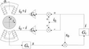
Figure 1: Schematic diagram of AMB system.
Equation (1) is generally linearized to facilitate mathematical processing and controller design. However, this paper considers the nonlinear effects of AMB by computing the first three terms of the Taylor series. The AMB force expression in the x-direction could be obtained as follows:
| (2) |
where k and k are the current stiffness and displacement stiffness of AMB. As shown in Fig. 1, in addition to the mechanical structure, the AMB system includes an electronic control system. The controller collects the rotor displacement signal from the displacement sensor and outputs the control current calculated by control algorithms. The control current is converted by the power amplifier to excite each stator winding, thereby generating the AMB attraction.
This research applies a general PID control algorithm. The sensor and power amplifier are modeled with gain G and G respectively. Thus, the mathematical model of the electronic control system can be expressed as follows:
where s is the complex variable, K is the proportional coefficient, K is the integral coefficient, K is the differential coefficient, T is the integral time constant, and T is the differential time constant. To avoid saturation of the power amplifier, a dead zone is pre-set by assigning K suitable parameters.
The most critical parameters of the PID controller are the proportional gain and differential gain, which determine the stable levitation and vibration attenuation capabilities. We can build a relationship between these two parameters and displacement stiffness and current stiffness [18]. Thus, the range of proportional gain and differential gain could be determined preliminarily by estimating the system’s stiffness and damping. The assigned proportional gain and differential gain ensure that the system stiffness is equal to 2-3 times the ’nature stiffness’, i.e., the absolute value of k. They also ensure the system damping ratio lies in the range of 20%-70%. In this way, the system can remain stable unless the power amplifier is saturated.
B. The nonlinear UMP
The sources of air gap eccentricity leading to UMP include dynamic eccentricity and static eccentricity. Dynamic eccentricity is caused by the rotor deviating from the equilibrium position during rotation. Incontrast, static eccentricity is caused by the not coinciding between the rotor’s static equilibrium position and the motor stator’s center. The mixed air gap eccentricity diagram is shown in Fig. 2. The outer circle is the motor stator’s inner surface, with the center labeled C, while the internal circle is the outer of the motor rotor, the center marked O. O’ is the transient position of the rotor. The offset r between O’ and C can be written as:
| (3) |
where r is the initial eccentricity, and is the initial phase angle.

Figure 2: Schematic diagram of motor’s air gap with mixed eccentricity.
The mixed eccentricity phase angle is expressed as follows:
| (4) |
When considering static and dynamic eccentricity simultaneously, the approximate expression of the air gap length at any spatial angle is derived as follows [9]:
| (5) |
where is the average air gap length without the eccentricity. According to the principle of the motor [20], for the three-phase synchronous motor with only one pole pair, the MMF in the air gap is derived as follows:
| (6) |
where F denotes the amplitude of MMF and is the power supply frequency. Therefore, the flux density distribution in the air gap can be estimated as follows:
| (7) |
According to [9], the above air gap permeability can be expanded using a Fourier series. Ignoring the tangential component of the magnetic density, assuming that the iron core permeability is infinite, and integrating Maxwell stress on the rotor surface, the UMP can be derived as follows:
| (8) |
Among them,
where R denotes the rotor radius, L denotes the air gap’s axial length, and denotes the air gap permeability:
Equation (8) shows that the UMP amplitude is mainly determined by the MMF and rotor’s position for the structure-determined motor system.
C. The rotor model
The rotor adopts the Jeffcott model. The unbalanced mass force (UMF) can be expressed as follows:
| (9) |
where m is the equivalent concentrated mass of the rotor at the disc, e is the mass eccentricity, and is the rotor’s rotation frequency. is the initial phase angle of unbalanced mass.
Combining Equations (2.1), (8), and (9), the differential equation for the lateral vibration can be obtained as follows:
| (10) |
Based on MATLAB/Simulink, we use the fourth-order Runge-Kutta method to calculate Equation (10). The parameters used in the simulation are listed in Table 1, related to AMB, and Table 2, related to UMP and UMF. The parameters used in this paper are consistent with the data in the two tables unless they are explicitly discussed.
Table 1: Parameters of the AMB System
| Name | Value |
|---|---|
| Air gap of the AMB, s(m) | 3.5e-4 |
| Air gap of the auxiliary bearing, (m) | 3e-4 |
| Coil turns, N | 94 |
| Bias current, i(A) | 1.5 |
| Magnetic pole area, A(m) | 2.21e-4 |
| Current stiffness, k(N/A) | 108 |
| Displacement stiffness, k(N/m) | 4.76e-5 |
| Sensor gain, G(V/m) | 20000 |
| Power amplifier gain, G(A/V) | 5 |
| Saturation limit of amplifier, K(A) | (-1.5, 2.5) |
| Proportional gain, K | 0.1 |
| Integral gain, K | 0.6 |
| Differential gain, K | 5.5e-5 |
| Integration time constant, T | 3/2 |
| Differential time constant, T | 1/1600 |
Table 2: Parameters of UMP and unbalance mass
| Name | Value |
|---|---|
| Motor rotor radius, R(m) | 60e-3 |
| Motor stator length, L(m) | 52e-3 |
| Air gap, (m) | 5e-3 |
| Amplitude of the resultant MMF, F (A) | 2000 |
| Initial phase of motor eccentricity, () | 225 |
| Rotor equivalent concentrated mass, m(kg) | 4.85 |
| Mass eccentricity, e(m) | 1e-10 |
| Initial phase angle of mass eccentricity, () | 45 |
D. Model verification
It can be seen from Equation (9) that the mass unbalance force of the rotor is small at low speed. Under the same UMP force, the smaller the mass unbalance force is, the smaller the distance r between the rotor center ‘O’ and the stator center ‘C’. Additionally, according to the definition in Section 2.2, as the rotor approaches the stator center, the UMP force generated by the dynamic eccentricity gradually decreases. Therefore, the rotor is relatively less disturbed by the unbalanced mass force and UMP force at low speed, and thus the vibration displacement is small. This can also be confirmed by the subsequent simulation results.
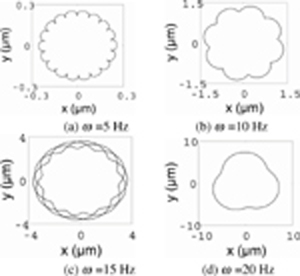
Figure 3: Rotor orbit for different rotation speeds.
Thus, the relationship between the AMB’s support force and rotor displacement is nearly linear, and the AMB can be regarded as a conventional bearing [21]. Hence, it is feasible to verify the accuracy of the model and calculation method proposed in this paper by comparing the rotor orbit at low speed with that in the commonly accepted literature [10, 12].
When the rotation frequency is 5, 10, 15, and 20 Hz, the rotor orbits are shown in Fig. 3. Their displacements lie in the range of 0.3 m to 30 m, not exceeding 2% of the AMB air gap. For the ordinary bearing rotor system considering UMP and UMF, the rotor orbits at the corresponding frequency are presented in [10] (Figs. 2 (a), (c), and (e)), as well as [12] (Fig. 6 (c)). These document results and our results are in good agreement. Thus the correctness of the program is verified.
The following calculation includes two parts: (1) the time domain and frequency domain response characteristics with or without UMP are analyzed and compared, and (2) the effects of different factors on the vibration spectra, rotor orbits and control signals near the resonance zone are investigated.
It should be noted that since the initial phase angle of mass eccentricity and initial phase angle of motor eccentricity (see Table 2) are 45 and 225 degrees, respectively, the waveforms of the unbalanced force, the UMP force, and the current overtime in the x-direction and the y-direction are theoretically the same, with a fixed phase difference. Unless explicitly discussed, the unbalanced force, UMP force, and properties mentioned below refer to the x-direction.
III. DYNAMIC PROPERTIES WITH OR WITHOUT UMP
A. Time-domain properties during the run-up
While gradually increasing the rotation speed, we calculated the transient response of displacement and current every 0.5 Hz, and recorded the maximum and minimum values when in a stable state.
The displacement and total current response results from 0 to 100 Hz are shown in Fig. 4. The maximum and minimum envelopes of rotor displacement are symmetrical, so only the maximum is plotted in Fig. 4 (a) while Fig. 4 (b) presents not only the maximum value of the coil current but also the envelope of the minimum value. The envelope of the maximum value and the minimum value of the coil current is not symmetrical. This is because the minimum value of the coil current is theoretically negative when the vibration is severe, while in practice it appears to be zero due to saturation limitations. We use continuous and dashed lines to represent the cases with and without UMP, respectively. Furthermore, we also divided the run-up process into a low-speed zone, a resonance zone, and a high-speed zone to describe clearly. The figures indicate the vibration not only in the low-speed zone but also in the high-speed zone is relatively slight, and the required control signal is small whether the system is excited by UMP or not.
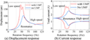
Figure 4: Amplitude response during run-up with or without UMP.
In contrast, UMP has a larger effect in the resonant zone. The figure presents that the system without UMP has only one resonant peak at 56 Hz. The vibration peak is about 104 m. The total current fluctuates in the range of 0.44 A to 2.56 A. UMP’s existence changes the vibration curve’s shape and strengthens vibration intensity significantly in the resonance zone. UMP splits the resonant peak from one into two at 46 Hz and 54 Hz. These two peaks have symmetry about the power supply frequency of 50 Hz. The displacement in the resonant zone reaches 185 m, exceeding half of the air gap. The current fluctuates from 0 to 3.28 A, coming to its lowest limit. It can be deduced that a little increment of disturbance may cause control failure and eventually produce a rub.
B. Rotor orbit and displacement spectra
The rotor orbit without considering the UMP at 56 Hz and its spectral analysis are shown in Figs. 5 (a) and (b). The orbit is a full circle, and its spectrum peaks appear at one, three, and five times the rotation speed. On this occasion, rotor motion behavior has no obvious nonlinear characteristics. It can be inferred that AMB mainly works in the linear range.

Figure 5: Rotor orbit and displacement spectrum at 56 Hz without UMP.
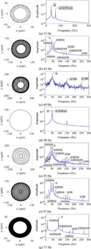
Figure 6: Rotor orbit and displacement spectra with UMP for different rotation speeds.
For the case with UMP, we calculate and display the rotor orbit and displacement response spectrum at the specific frequencies (35 Hz, 43 Hz, 49 Hz, 50 Hz, 55 Hz, 57 Hz, and 77 Hz) in the resonant zone and high-speed zone, as shown in Fig. 6.
The rotor’s rotation motions and vibration characteristics are enriched by UMP, compared with Fig. 5. It shows that every displacement spectrum has two noticeable main harmonic components at and + 2(50-), consistent with the two main resonant frequencies in Fig. 4. Moreover, the peak at is always more prominent than that at + 2(50-). It can be attributed to the fact that UMP amplitude depends highly on the dynamic eccentricity caused by the UMF. When the rotation speed approaches the two main resonance speeds from the lower or higher speed, the harmonic amplitude at + 2(50-) excited by UMP’s introduction is gradually close to that at , which is reflected in the more significant fluctuation of rotor orbit ultimately. When the rotation speed is 50 Hz, UMP and UMF collectively focus on the same spectrum, and thus the rotor orbit is a circle.
The other sub-harmonics in Fig. 6 all occur at the frequency – the linear combination of rotation frequency and power supply frequency. Only Fig. 6 (c) is an exception, whose behavior is close to chaos due to excessive vibration. These sub-harmonic frequency components occupy an increasingly important position with the rotation speed close to two main resonant speeds, reflecting the nonlinearity in the resonantzone.
Furthermore, the frequency waterfall chart of dynamic response for different rotation speeds is displayed in Fig. 7.
Frequency components radiate to the outer periphery with 50 Hz, 150 Hz, and 250 Hz as the symmetric center point, on the whole. These frequencies can be uniformly described as 2n (50-) + 2n50, (n and n are natural numbers), and their amplitudes gradually decrease as n and n increase.
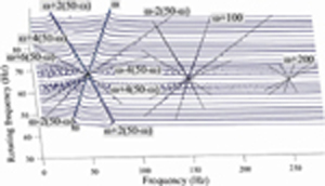
Figure 7: Frequency waterfall chart of displacement response with the UMP.
The displacement spectra exhibit much difference from that in [9–12]. It can be concluded that their linear combinations between the rotation frequency and supply frequencies are different, i.e., there exist differences in the coupling effects of the magnetic field and the structure field between the AMB-rotor system and the ordinary bearing-rotor system. If the figure is investigated further, it is noticed that the upper half of the symmetry axis with a rotation frequency of 50 Hz in Fig. 7 is similar to that of the ordinary bearing-rotor system, although the direction where frequency components are enhanced is opposite.
IV. EFFECTS OF DIFFERENT FACTORS
A. Effects of mass eccentricity
The UMF is the fundamental reason that causes the rotating rotor to deviate from its static equilibrium position, resulting in the dynamic eccentric UMP. It is of great significance to investigate the vibration characteristics under different e. Figure 8 is the rotor’s displacement response in the run-up process when e is 0.1e-4, 0.4e-4, 0.8e-4, and 1.2e-4.
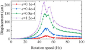
Figure 8: Displacement response during the run-up for different e.
It can be seen that e amplifies displacement vibration of the whole run-up process and enlarges the effect of UMP as a result. The two resonant peaks split by UMP are away from each other, and the peaks become more and more outstanding with e increasing. Overall, the figure demonstrates that e plays a crucial role in the vibration behavior, which means with small UMF, the rotor can keep slight vibration even if UMP is quite large.
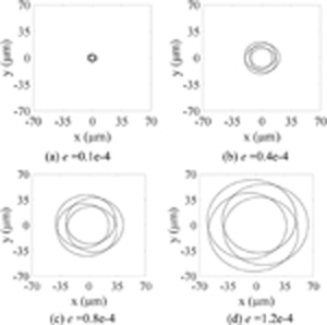
Figure 9: Rotor orbit at 80 Hz for different e.
Specifically, an example of dynamic characteristics at a particular frequency for different e is described below. Figures 9-11 are the rotor orbit, displacement spectrum, and control current’s time history at 80 Hz, respectively.
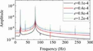
Figure 10: Displacement response spectra at 80 Hz for different e.
Figure 9 show that increasing e has a negligible effect on the periodic numbers and the orbit shape, although it expands both the interior boundary and external boundary of rotor orbit. It is also can be observed that the frequency components of displacement response become more and more evident with e increasing as shown in Fig. 10.
Figure 11 depicts the fluctuation range of the control current being enlarged by e. As e increases, the control current waveform changed gradually from the single-period sine waveform similar to UMF to that with multiple periods, approaching the UMP. The reason for the phenomenon is that UMP increases rapidly with the displacement vibration increasing and progressively accounts for a higher proportion of the exciting force exerted on the rotor.
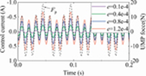
Figure 11: Time history of the control current at 80 Hz for different e.
B. Effects of main control parameters
Unlike traditional mechanical bearings, the support characteristics of the AMBs are not fixed but are affected by the control parameters even when the mechanical structure and working conditions are determined. The influence of the main control parameters is investigated as follows.
(1) Proportional gain
Figure 12 is the displacement response in the run-up process when the proportional gain is at 0.08, 0.1, 0.12, and 0.14. It should be noted that to increase the applicable range of K, the mass eccentricity and the differential gain are reduced and increased to e = 0.8e-4 and K = 6, respectively. The other parameters remain the same as those in Tables 1 and 2.
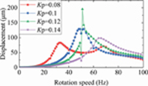
Figure 12: Displacement response during the run-up for different K.
Results show that the increase of K moves progressively the entire resonance zone to the right in the coordinate system, which can be attributed to the fact that K has a positive correlation with the system stiffness. With a small K, two resonant peaks stand outstandingly on both sides of 50 Hz, far apart. In this case, the resonance zone has the characteristics of a wide span and low amplitude. When K is increasing, the two prominent resonant peaks are approaching each other, and the amplitude is gradually rising. Then, the two peaks merge into one, with the peak value dropping as Kincreases.
At 51 Hz, rotor orbit, displacement spectrum, and control current time history plot are analyzed in Figs. 13-15, respectively.

Figure 13: Rotor orbit at 51 Hz for different K.
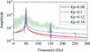
Figure 14: Displacement response spectra at 51 Hz for different K.
Figure 13 shows that as K varies, the circular orbit’s inner boundary does not change as much as the external edge. It can also be concluded that the vibration at 51 Hz in the resonant zone shows a trend of first increasing and decreasing as K increases. The control current increases at the same pace as the displacement, as illustrated in Fig. 15. This is because the rise in K moves the left resonant peak in the coordinate system from the left of 51 Hz to the right side, which finally results in severe vibration at 51 Hz when K is assigned an intermediate value of 12000. Figures 13 (c) and 14 demonstrate that the motion state at K = 12000 is close to chaos. On this occasion, the control current has been saturated, as shown in Fig. 15.
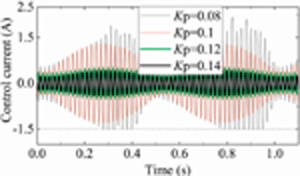
Figure 15: Time history of the control current at 51 Hz for different K.
In summary, a critical conclusion we got is that a slightly larger K is more appropriate when controlling a rotor with a larger UMP. The rotor with a small K has a long span for the resonant zone. Simultaneously, the medium value of K concentrates the resonant peaks and enlarges the vibration, and too large K also has certain disadvantages, such as a smaller relative damping and larger control current.
(2) Differential gain
When the differential coefficient K is 5e-5, 6e-5, 9e-5, and 1.6e-4, while the other parameters are the same as those in Table 1 and Table 2, the displacement response during run-up is shown in Fig. 16. It can be found K has little effect on the resonance frequency but dramatically affects the resonance zone’s amplitude, which is attributed to the fact that K mainly determines the system damping. Therefore, it is a very effective means to suppress the rotor vibration by improving the differential gain.
Figures 17 and 18 show the rotor orbit and displacement response spectra at 46 Hz for different K. When K is the smallest value of 5, continuous and abundant frequency components come into view in the displacement spectra of Fig. 18. From Fig. 17 (a), it also can be observed that the rotor is rotating irregularly, accompanied by large fluctuations. With the increase of K, the rotor orbit boundary’s outer diameter is dropping much while the inner edges are reduced in a relatively gentle way. For further explanation in Fig. 18, the two prominent frequency components are reduced, and the others are suppressed and even eliminated. The time history of the control current in Fig. 19 shows that the current gradually changes from multi-period vibration to single-period vibration with differential gain increasing.
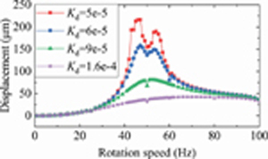
Figure 16: Displacement response during the run-up for different K.

Figure 17: Rotor orbit at 46 Hz for different K.
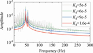
Figure 18: Displacement response spectra at 46 Hz for different K.
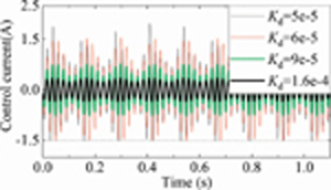
Figure 19: Time history of the control current at 46 Hz for different K.
C. Effects of the UMP
The UMP exerted on the rotor in a static levitation state is called the static eccentricity UMP. The UMP generated by leaving the stationary equilibrium position due to rotational movement is called the dynamic eccentricity UMP. We use the MMF F and the static eccentricity r to measure the dynamic and static eccentric UMP, respectively.
(1) MMF
When F is smaller, though the vibration amplitude in Fig. 20 is more extensive, its vibration trend is similar to that without the UMP, as shown in Fig. 4. It is observed that the growth of UMP moves the resonance zone slightly to the left, expands its span, and increases the resonant peaks. Larger F splits the single resonant peak into two symmetrical peaks and drives the two away from each other. However, F plays a minor role in low-speed and high-speed regions.
Assigning F values of 500, 1100, 1700, and 2300, the rotor displacement response during the run-up is depicted in Fig. 20.

Figure 20: Displacement response during the run-up for different F.
Figure 21 shows the rotor orbits with different F at 80 Hz of the high-speed range. It can be noticed that the interior boundary of the orbit zone gradually moves closer to the center as F increases, while the external edge seems like remaining constant. Consequently, F changes the orbit’s shape by affecting the interior boundary’s size instead of the number of periods.

Figure 21: Rotor orbit at 80 Hz for different F.
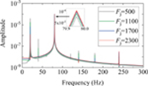
Figure 22: Displacement response spectra for different F.
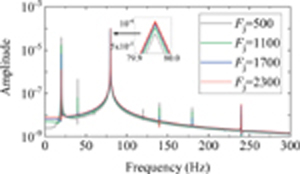
Figure 23: Time history of the control current at 80 Hz for different F.
The displacement response spectra are depicted in Fig. 22. It indicates that increasing F slightly attenuates the frequency components at rotation speed but strengthens and enriches the other spectra greatly. The time history of the control current is illustrated in Fig. 23. It reveals that the waveform of the control current changes from an apparent single-cycle motion to a multi-cycle motion composed of 80 Hz and 20 Hz. However, the current peak remains unchanged, about 0.5 A with F increasing.
(2) Static eccentricity
All of the above orbit plots are centrosymmetric, which is due to such a small value of the static eccentricity (r =1e-10) adopted that it can be ignored. The aim is to remove the influence of r and focus on the effects of other factors. However, r is inevitable in reality and affects the rotor dynamic characteristics significantly.
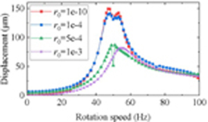
Figure 24: Displacement response during run-up for different r.
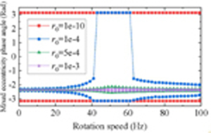
Figure 25: Mixed eccentric phase angle response for different r
Figures 24 and 25 are the displacement response and the mixed eccentric phase angle (see Fig. 2) response with different r during the run-up. Figure 24 shows that increasing r narrows the resonance zone and moves it to the right in the coordinate’s right. It also can be found that as r reaches a certain threshold, the resonant peak decreases sharply. Similarly, according to Fig. 25, the rotor makes small rotations in the specific direction of the coordinate origin O (see Fig. 2) rather than making a revolution motion about O, as r reaches the threshold. It is because in this case, the centrifugal effects generated by UMF are challenging to break free from the shackles of static eccentric UMP.
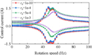
Figure 26: Control current response for different r
Figure 26 is the response of the maximum and minimum current during the run-up. It indicates that changing r shifts the symmetry axis of the control current up and down. The control current’s balanced position is upward with increasing according to the time history plot in Fig. 27.
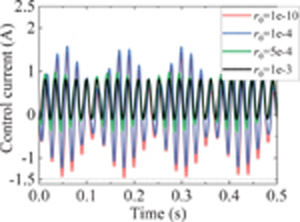
Figure 27: Time history of the control current at 46 Hz for different r.

Figure 28: Rotor orbit at 46 Hz for different r
Figure 28 shows the rotor orbit at 46 Hz. It demonstrates that the orbit shape affected by r is axisymmetric rather than central symmetry. The displacement response spectra at 46 Hz in Fig. 29 shows that static eccentricity greatly enriches response frequencies compared with Fig. 7 at the same rotation frequency. It enhances the rotor nonlinear motion characteristics by causing new frequency components at 100 Hz and 200 Hz. These new spectra can be described with the uniform expression of 2k *50 2k(50-) (k and k are natural numbers) and their amplitude has a negative relationship with k and k, as shown in Fig. 30.
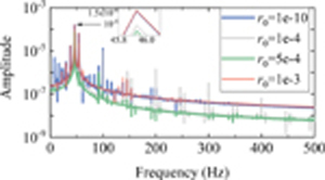
Figure 29: Displacement response spectra at 46 Hz for different r.
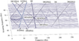
Figure 30: Waterfall diagram of rotor displacement vibration with the static displacement r=1e.
V. CONCLUSION
The rotor model suffering nonlinear UMP and nonlinear UMP AMB force is established. The effect of control parameters and UMP on the dynamic characteristics when the rotor crosses critical speeds is investigated in detail. The typical conclusions are summarized as follows:
(1) Displacement spectrum of the magnetic levitation rotor system with UMP is quite different from the previous research results with ordinary bearings. UMP splits the original single resonant peak into two symmetrical resonant peaks about the power supply frequency. UMP widens the frequency span of the resonant zone and amplifies the vibration during resonance. With the combined action of the UMP and AMB, the displacement spectrum appears abundant frequency components. Without considering the static eccentricity, these spectral frequencies can be described by 2n(50-) + 2n50 (n and n are natural numbers).
(2) The effect of static eccentric UMP is similar to the force with constant direction and amplitude. To offset the static eccentric UMP, the controller actively generates the bias current as part of the control current. The static eccentric UMP excites the rotor’s nonlinear dynamic characteristics, resulting in appearing new frequency components in the displacement response spectrum, coexisting with the previous frequency components. These new spectra can be summarized with the formula of 2k50 2k(50-) (k and k are natural numbers).
(3) Though the AMB-rotor system without UMP works in a linear working state, UMP’s existence may saturate the control current and thus strengthen the nonlinear characteristics of AMB force, which can easily produce control failure and rotor drop.
(4) A slight increment in control parameters causes a significant effect on the dynamic responses. In particular, K affects the amplitude and span of the resonance zone. K has an important impact on the vibration peak. Applying slightly larger K and K is recommended to narrow the resonance zone and suppress the resonant vibration of the AMB-rotor system with large UMP.
ACKNOWLEDGMENTS
This work was supported by the fund of the State Key Laboratory of Technologies in Space Cryogenic Propellants, SKLTSCP202104.
REFERENCES
[1] G. Schweitzer, E. H. Maslen, H. Bleuler, M. Cole, and A. Traxler, Magnetic Bearings Theory, Design, and Application to Rotating Machinery, Springer-Verlag, Berlin, 2009.
[2] S. Y. Yoo, W. R. Lee, Y. C. Bae, and M. Noh, “Design of magnetically levitated rotors in a large flywheel energy storage system from a stability standpoint,” Journal of Mechanical Science and Technology, vol. 24, no. 1, pp. 231-235,Jan. 2010.
[3] S. Y. Zhang, W. Pan, C. B. Wei, and J. H. Wu, “Structure design and simulation research of active magnetic bearing for helium centrifugal cold compressor,” Proc. of the Cryogenic Engineering Conference and International Cryogenic Materials Conference, Madison WI, Jul. 2017.
[4] R. Belmans, W. Geysen, and H. Jordan, “Unbalanced magnetic pull and homopolar flux in three phase induction motors with eccentric rotors,” International Conference on Electrical Machines, vol. 3, pp. 916-921, 1982.
[5] R. K. Gustavsson and J. O. Aidanpaa, “The influence of nonlinear magnetic pull on hydropower generator rotors,” Journal of Sound and Vibration, vol. 297, no. 3-5, pp. 551-562, 2006.
[6] U. Werner, “Rotordynamic model for electromagnetic excitation caused by an eccentric and angular rotor core in an induction motor,” Archive of Applied Mechanics, vol. 8, no. 3, no. 8, pp. 1215-1238, 2013.
[7] H. Kim, J. Nerg, T. Choudhury, and J. Sopanen, “Rotordynamic Simulation Method of Induction Motors Including the Effects of Unbalanced Magnetic Pull,” IEEE Access, no. 8, pp. 21631-21643, 2020.
[8] R. Belmans, A. Vandenput, and W. Geysen, “Calculation of the flux density and the unbalanced pull in two pole induction machines,” Archiv Für Elektrotechnik, vol. 70, no. 3, pp. 151-161, 1987.
[9] D. Guo, F. Chu, and D. Chen, “The unbalanced magnetic pull and its effects on vibration in a three-phase generator with eccentric rotor,” Journal of Sound and Vibration, vol. 254, no. 2, pp. 297-312, 2002.
[10] X. Xu, Q. Han, and F. Chu, “Electromagnetic vibration characteristics of an eccentric rotor with a static load,” Qinghua Daxue Xuebao/Journal of Tsinghua University, vol. 56, no. 02, pp. 176-184, 2016.
[11] X. Xu, Q. Han, and F. Chu, “Nonlinear vibration of a generator rotor with unbalanced magnetic pull considering both dynamic and static eccentricities,” Archive of Applied Mechanics, vol. 86, no. 8, pp. 1521-1536, 2016.
[12] X. Xu, Q. Han, and F. Chu, “A four degrees-of-freedom model for a misaligned electrical rotor,” Journal of Sound & Vibration, no. 358. pp. 356-374, 2015.
[13] H. Liu, Y. Wu, and X. Wang, “Nonlinear normal modes and primary resonance for permanent magnet synchronous motors with a nonlinear restoring force and an unbalanced magnetic pull,” Nonlinear Dynamics, vol. 97, no. 2, pp. 1197-1213, 2019.
[14] L. Zhang, Z. Ma, and B. Song, “Dynamic characteristics of a rub-impact rotor-bearing system for hydraulic generating set under unbalanced magnetic pull,” Archive of Applied Mechanics, vol. 83, no. 6, pp. 817-830, 2013.
[15] H. Li, H. Geng, H. Lin, and S. Feng, “Analysis on dynamical properties of the foil bearing rotor system with the unbalanced magnetic pull,” International Journal of Applied Electromagnetics and Mechanics, vol. 64, no. 1-4, pp. 181-189,2020.
[16] T. Du, H. Geng, Y. Sun, H. Lin, Zhang Yanan, L. Yu, “Theoretical and experimental researches of active magnetic bearing systems for high-speed PM machines,” International Journal of Applied Electromagnetics and Mechanics, vol. 59, no. 3, pp. 891-901, 2019.
[17] J. Li, J. Zhou, and H. Wu, “Vibration mechanism analysis of magnetic levitation rotor system for low temperature waste heat power generation,” Proc. of 16th International Symposium on Magnetic Bearings, Beijing, China, no. 57, pp. 1-8, 2018.
[18] D. Chong, P. Ilya, J. Pyrhonen, X. Bao, “Unbalanced magnetic pull compensation with active magnetic bearings in a 2 MW high-speed induction machine by FEM,” IEEE Transactions on Magnetics, vol. 54, no. 8, 2018.
[19] Z. Wang, C. Mao, and C. Zhu, “A design method of PID controller for active magnetic bearings-rigid rotor systems,” Process of the CSEE, vol. 38, no. 20, pp. 6154-6163, 2018.
[20] B. Wu, W. Sun, Z. Li, and Z. Li, “Circular whirling and stability due to unbalanced magnetic pull and eccentric force,” Journal of Sound and Vibration, vol. 330, no. 21, pp. 4949-4954, 2011.
[21] J. C. Ji, C. Hansen, and A. Zander, “Nonlinear dynamics of magnetic bearing systems,” Journal of Intelligent Material Systems & Structures, vol. 19, no. 12, pp. 1471-1491, 2018.
BIOGRAPHIES

Shuyue Zhang received a Ph.D. from the University of Chinese Academy of Sciences and a Bachelor’s degree from Dalian University of Technology. Now she works at the School of Mechanical and Electrical Engineering, Chuzhou University. Her main research interests include rotor dynamic and active magnetic bearing control.

Zaibin Chena received his Ph.D. from University of Chinese Academy of Sciences and a bachelor degree from Sichuan University. Now he is an Assistant Professor in School of Mechanical and Electrical Engineering, Chuzhou University. His main research interests include servo motors and their control.

Xiaolian Lva received her Ph.D. from Shenyang Agricultural University. She is currently serving as a Professor in School of Mechanical and Electrical Engineering at Chuzhou University. Her research mainly concerns mechanical design theory and its application.

Hongli Yana now is an Associate Professor in School of Mechanical and Electrical Engineering, Chuzhou University. Her research interests mainly are communication system modeling and wireless communication.

Jihao Wua is currently a Professor and Ph.D. Supervisor of University of Chinese Academy of Sciences. His research interests are magnetic levitation rotating machinery, low temperature rotating machinery, and refrigeration machine.

Yuanliang Zhou received a Ph.D. from Dalian University of Technology. Now he is an Associate Professor of Mechanical and Electrical Engineering, at Chuzhou University. His research mainly concerns electromagnetic field simulation, electromagnetic materials, and their engineering application.
ACES JOURNAL, Vol. 37, No. 10, 1096–1109
doi: 10.13052/2022.ACES.J.371010
© 2022 River Publishers