Cavity-Backed Slot V2X Antenna for Automotive Applications
Mohamed O. Khalifa, Ahmad M. Yacoub, and Daniel N. Aloi
1Department of Electrical Engineering, Oakland University, Rochester, MI 48309, USA
MKhalifa@Oakland.edu, Ahmadyacoub@Oakland.edu, Aloi@Oakland.edu
Submitted On: October 25, 2021; Accepted On: February 4, 2022
Abstract
In this work, a cavity-backed slot antenna has been designed to cover vehicle-to-everything (V2X) frequencies ( GHz). The antenna is made to be easily integrated in a vehicle windshield or rear mirror. The cavity-backed slot antenna does not require a ground plane to sit on which makes it an ideal model for below horizon performance. Antenna simulation has been done using high-frequency structure simulator (HFSS) and then on-foam and on vehicle’s windshield measurements have been carried out inside an anechoic chamber. The proposed antenna achieved a linear average gain (LAG) above 2.5 dBi in the targeted V2X elevation and azimuth angles with better than 15 dB return loss. The antenna performance has been reported in terms of reflection coefficient, surface current density, radiation pattern, LAG, and efficiency.
Keywords: Automotive antennas, V2X, 5G, V2I, V2P, V2N, V2V, cavity-backed slot antenna.
I. INTRODUCTION
In the recent years, the automobiles industry has been drastically affected by the new technology advancements. The vehicle is no longer made of primitive mechanical components; only, however, it is loaded with many sensors for various applications. Long road trip hours increased the possibility of car accidents and other serious socioeconomic problems. Vehicle-to-everything (V2X) communication technology includes vehicle-to-vehicle (V2V), vehicle-to-infrastructure (V2I), vehicle-to-network (V2N), and vehicle-to-pedestrian (V2P), and it allows the vehicle’s system to exchange information with infrastructure, pedestrians, and vehicles to smoothen traffic flow and improve humans’ safety. There are two implementable schemes for V2X: dedicated short-range communication (DSRC) and 5G network. Both schemes can operate with each other to result in a complete solution for V2X communication. The 5G cellular communication can be considered as a backup to the DSRC while supporting high data rates that can lengthen the communication path beyond the short range of the DSRC technology [1].
Vehicular V2X antennas are required to communicate with vehicles, infrastructure, network, and pedestrians that are located at various elevations with respect to the vehicle’s antenna. Thus, good coverage in Theta angles range is important to make sure that good reception performance is achieved for electromagnetic waves originating from antennas mounted in high locations like base station towers as well as to cover waves incident from below-horizon angles [2].
In [3], two V2X antennas are designed to fit in an automotive shark-fin; however, low average gain of dBi was reported at 5.9 GHz. A tri-polarized antenna was designed to cover 5G and V2X frequencies in [4] with an H-plane gain of dBi in the V2X band; however, it comes with an increased antenna volume with dimensions of . Similar drawbacks of large volumes can also be seen in [5–9] with less than zero gain in [7] and [8], whereas a gain of 0.97 dBi was reported in [9]. A mean realized gain of 0.043 dBi was achieved in [10] with a multiband antenna that covers long-term evolution (LTE) and V2X with a big volume of . In addition to those similar large volumes, multiband designs that cover both LTE and V2X with maximum realized gain values of and 2 dBi are reported in [11] and [12], respectively. In [13], a quarter-wave balun fed Vivaldi antenna with dimensions of was designed and an average gain of dBi was reported around 5.9 GHz. The work in [2] shows a peak gain of 8 dBi at 5.9 GHz; however, it does not show average gain values and it does not tell at which elevation angles this peak gain is achieved. Unlike the above designs, the proposed cavity-backed slot antenna is made to be attached to the vehicle windshield instead of the roof which allows improved radiation pattern for elevation angles and consequently improve the V2X communication scheme.
The work in this paper is organized in two sections: Section II details the antenna element layout and the design goals; Section III presents the cavity-backed slot antenna simulation and measurements results and compares it to the available work in literature.
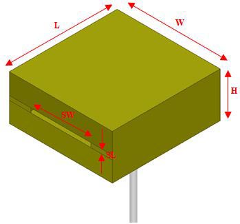
Figure 1: Cavity-backed slot antenna dimensions.

Figure 2: Cavity-backed slot antenna dimensions with the top side removed.
II. ANTENNA ELEMENT LAYOUT
The cavity-backed slot antenna is constructed of metal sheet with volume of 40.5 mm height 38.7 mm length 16.8 mm width. A coaxial cable is used to feed the antenna where its center pin is used as a monopole to excite the cavity-backed slot antenna. Figures 1 and 2 show the proposed antenna with geometrical dimensions highlighted. The feeding monopole is made of two parts, the lower part which is coaxial cable center pin with a length (LFL) of 1.74 mm and diameter of 0.2 mm, whereas the top part has a length (FL) of 10.97 mm and a wider diameter (FD) of 1.7 mm to help in having wider overall bandwidth for the monopole.
The total length of the monopole is set to be 12.71 mm which is a quarter-wavelength at 5.9 GHz and can be calculated as follows:
where c is the speed of light () and f = 5.9 GHz. The feeding monopole is located at approximately from the back side (opposite to the slot side) of the cavity to allow for an in-phase reflection of energy from the back of the cavity to the slot side. It is assumed that the cavity is filled with air and experimental trials are used to determine the geometrical dimensions of the cavity with the assumption that mode will be excited in the antenna. Table 1 shows the values of various antenna parameters with their finalvalues.
Table 2 lists the targeted design goals for the proposed V2X antenna in terms of polarization, reflection coefficient, efficiency, and linear average gain (LAG). The design goals are generated based on the anticipated coverage and performance of V2X antenna based on the requirements of some of the original equipment’s manufacturer (OEMs) in the automotive industry.
Table 1: Values of the cavity-backed slot antenna geometrical parameters
| H | 16.8 | FL | 11 |
| L | 40.5 | LFL | 1.74 |
| W | 38.7 | FD | 1.7 |
| SW | 22.5 | FX1 | 13.3 |
| SL | 1.6 | FY | 19.35 |
Table 2: Design guidelines
| Polarization | Vertical linear polarization (VLP) |
| Reflection coefficient | dB (2:1 VSWR) |
| Avg. total efficiency | 45% |
| LAG for solid angle: |
Minimum of 2 dB |
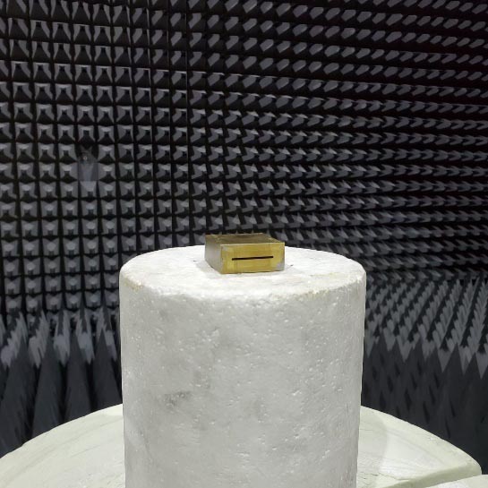
Figure 3: On-foam measurement setup.
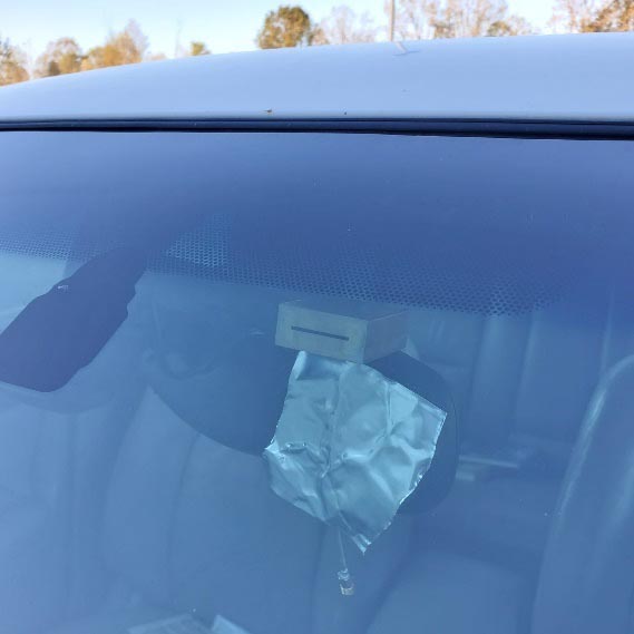
Figure 4: Antenna placement on vehicle windshield.
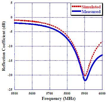
Figure 5: Comparison of reflection coefficient (dB) between simulation and measurement.
The antenna simulation is done using high-frequency structure simulator (HFSS), measured on-foam inside an anechoic chamber as in Figure 3, and, finally, vehicle level measurement has been performed with the antenna mounted on the vehicle’s windshield as can be seen in Figure 4.
III. PROPOSED ANTENNA SIMULATION AND MEASUREMENT RESULTS
The proposed antenna’s reflection coefficient is depicted in Figure 5. Similar matching characteristics between the simulation and measurements can be observed with mid-band return losses of 20 and 22 dB in simulation and measurements, respectively. In order to further study the antenna, the surface current density is reported in Figure 6. The high values of surface current density at 5.9 GHz near the cavity slot indicates that most of the energy radiated by the feeding monopole is exiting the cavity through the slot either directly or after it bounces from the back of the cavity.
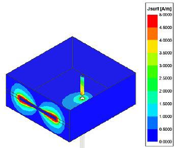
Figure 6: Simulated surface current density (A/m) at 5.9 GHz.
Next, a parametric study has been conducted to study the effect of various cavity parameters on the V2X antenna performance and to check the possibility of miniaturizing the antenna without impacting the performance. The study started by changing the front side slot width (SW) and length (SL) by 1 mm around the optimized value listed in Table 1. Increasing slot length or width by 1 mm moves the resonance frequency toward lower frequencies while reducing them shifts the resonance frequency higher as Figures 7 and 8 suggest. In fact, increasing SL or SW increases resistance and inductance the input impedance antenna input impedance, while the opposite happens when SL and SW lengths are reduced. The impact of changing slot dimensions can easily be understood by invoking the Babinet’s principle where the horizontal slot can be replaced by the corresponding vertical half-wave dipole. Since increasing the slot dimensions is equivalent to increasing dipole dimension, previous argument is proved to be valid. Furthermore, the cavity with the slot (or equivalent dipole) acts like a parasitic director to help make the antenna more directive to the front. Since the director length is typically slightly less than half of the wavelength at 5.9 GHz, SW optimized value was found to be 22.5 mm which corresponds to at 5.9 GHz.
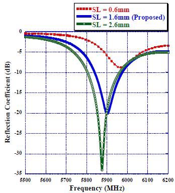
Figure 7: Effect of changing SL on reflection coefficient.
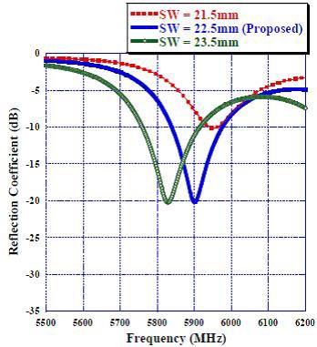
Figure 8: Effect of changing SW on reflection coefficient.
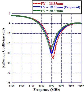
Figure 9: Effect of changing FY on reflection coefficient.
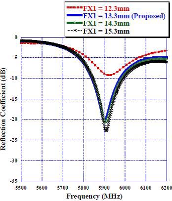
Figure 10: Effect of changing FX1 on reflection coefficient.
Fine-tuning of the resonance frequency can be achieved by adjusting the y-axis sides of the cavity, where increasing distance between monopole and cavity sides along the y-axis (FY) allows better radiation characteristics for bigger wavelength while the opposite happens when monopole to side distance is reduced as depicted in Figure 9. In order to find the minimum dimensions that result in a satisfactory performance of the V2X antenna, the relative distances between the monopole and x-axis sides of the cavity have been studied. Figure 10 shows the effect of changing monopole to cavity backside distance (FX1). It can be noticed that reducing FX1 length by only 1 mm entirely sabotages the antenna reflection coefficient and, consequently, the overall antenna performance, whereas the change in reflection coefficient due to 1 or 2 mm FX1 increase is almost insignificant. As a result, the optimized value of FX1 = 13.5 mm represents the smallest monopole to cavity back-side distance that allows for satisfactory V2X antenna performance according to the requirements listed in Table 2. Similar analysis can be shown for monopole to cavity front-side distance (FX2 = L-FX1 = 27.2 mm) as illustrated in Figure 11. For this parameter, the variation step has been set to 2 mm to allow for noticeable change in the reflection coefficient response. As it can be seen in Figure 11, as FX2 value decreases from 31.2 mm, antenna resonance frequency is shifted toward higher frequencies and a perfect matching is obtained around FX2 = 27.2 mm. Reducing FX2 value beyond 27.2 mm results in a complete mismatch of the antenna at 5.9 GHz, indicating that the antenna size cannot get any smaller in that direction. To shed some light on the nature of change the cavity-backed slot antenna exhibits when the front side of cavity is pushed toward the monopole, the antenna input impedance is analyzed at different FX2 distances. As shown in Figure 12, the antenna input impedance at FX2 = 27.2 mm is 41.5 + j2.6 at 5.9 GHz. increasing FX2 by 2 and 4 mm results in increased input reactance (inductive effect) of j20 and j39, respectively, while having insignificant effect on the input resistance (around 5 ) across the whole V2X band. However, when FX2 is reduced to 25.2 mm, the antenna sees a huge input impedance of 191+j51 at 5.9 GHz with a significant increase in antenna input resistance. FX1 and FX2 distances of the cavity-backed slot antenna were found to have a great impact on the antenna performance, and they were optimally set to be slightly greater than quarter and half of the wavelength at 5.9 GHz, respectively. In summary, by optimizing the values of FX1, FX2, FY, SW, and SL, the smallest cavity-backed slot antenna that satisfies V2X design requirements listed in Table 2 can be found.
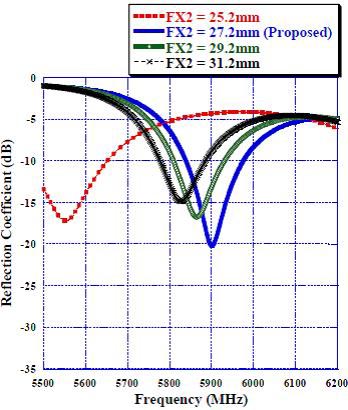
Figure 11: Effect of changing FX2 on reflection coefficient.
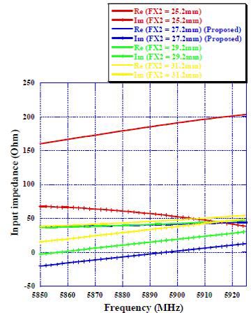
Figure 12: Effect of changing FX2 on antenna input impedance.
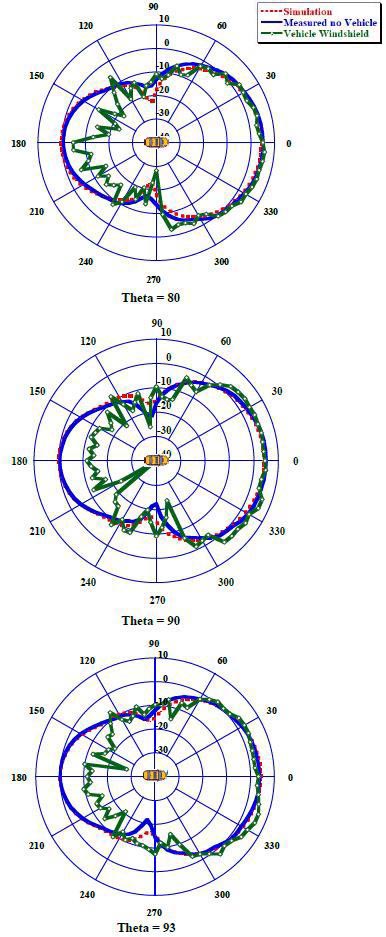
Figure 13: Realized vertical gain at 5.85 GHz for simulated, measured, and on vehicle windshield at Theta = 80, Theta = 90, and Theta = 93.
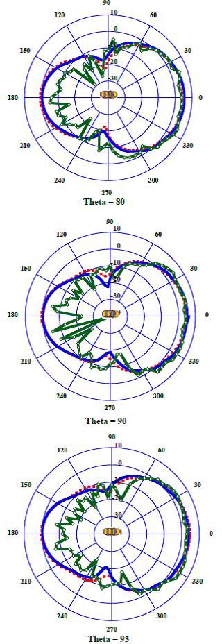
Figure 14: Realized vertical gain at 5.9 GHz for simulated, measured, and on vehicle windshield at Theta = 80, Theta = 90, and Theta = 93.
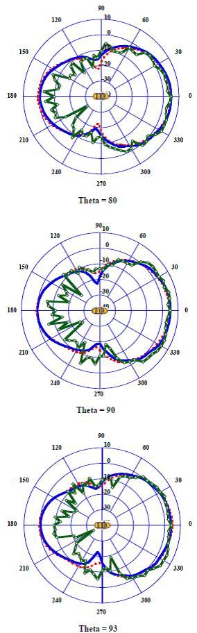
Figure 15: Realized vertical gain at 5.925 GHz for simulated, measured, and on vehicle windshield at Theta = 80, Theta = 90, and Theta = 93.
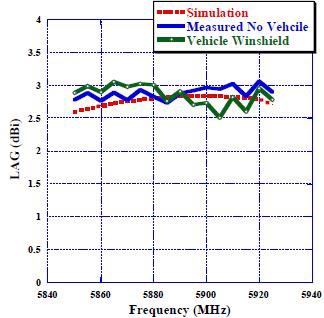
Figure 16: LAG against frequency compassion between simulation, measured on-foam, and measured on vehicle’s windshield.
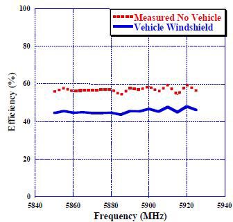
Figure 17: Efficiency against frequency compassion between measured on-foam and measured on vehicle’s windshield.
To meet the V2X wide azimuth front beam and various elevation angle requirements, the cavity SW and length must be carefully optimized. In Figures [13–15], the antenna radiation patterns have been reported at different elevation angles and at sample frequencies across the V2X band. The elevation angles are selected in a way that will reflect various V2X communication scenarios. For example, vertical gain radiation pattern at Theta = 80 will mimic electromagnetic waves incident from base station towers or traffic light signals, whereas Theta = 90 and Theta = 93 will represent waves originating from other cars at or below the horizon, respectively. The on-vehicle’s windshield average vertical gain in between azimuth angles range at 5.9 GHz was found to be 2, 2.8, and 2.2 dB at Theta angles 80, 90, and 93, respectively.
Since the proposed antenna does not sit on a ground plane by design, the antenna demonstrates a good performance below horizon and that can be seen by looking at average vertical realized gain at Theta = 93 which was found to be 2.4, 2, and 2.3 dB at 5.85, 5.9, and 5.925 GHz, respectively.
Table 3: Literature review summary
| Proposed | Cavity-backed slot | 40.5 38.7 16.8 | 2.75/6.5 | Yes |
| [2] | Disc shape | NA/8 | NA | |
| [3] | Printed monopoles | 14 0.8 28 14 1.6 50 |
/NA /NA |
NA |
| [4] | Tri-polarized | 76 76 17 | 2.4/2.88 | NA |
| [7] | V-shaped slot | NA | NA | |
| [8] | Stacked microstrip monopolar patch | 0/7.5 | NA | |
| [9] | Patch antenna | NA/0.97 | NA | |
| [10] | Printed flexible | 120 70 0.1 | 0.043/4.6 | NA |
| [11] | Three-port multiband antenna | 60 87 1.6 | NA/ | NA |
| [12] | Combined LTE and V2X antenna | 290 40 7.6 | NA/2 | NA |
| [13] | Vivaldi antenna | 190 187.5 187.3 | -4/NA | NA |
A practical way to measure automotive V2X antenna performance is by calculating the LAG across theta angles from 88 to 91 as in Table 2. The theta angles simulate the electromagnetic waves exchanged between vehicles. LAG measured in dB for a frequency (f) and polarization ( is given by
where is the spherical coordinate theta angle in degrees referenced by the index ; is the total number of theta angles (four angles for theta from 88 to 91); is the spherical coordinate phi angle in degrees referenced by the index ; is the total number of phi angles (360 angles for phi from 0 to 359); and in the gain in linear units for a discrete point on the spherical surface for a given frequency (f) andpolarization ().
Figure 16 depicts the LAG against frequency for simulated, measured on-foam, and measured on a vehicle’s windshield. In all three cases, the LAG has stayed above 2.5 dBi across V2X frequencies, satisfying the design goals listed in Table 2. Finally, the total efficiency of the antenna measured on-foam and on vehicle’s windshield is reported across V2X frequencies in Figure 17. The on-foam measurements show a 56% average total efficiency, whereas the on-vehicle measurements exhibit reduced average efficiency of 45.5% indicating that antenna performance is compromised at other elevation and azimuth angles apart from the targeted ones due to reflections within the vehicle.
Table 3 compares the cavity-backed slot antenna to other V2X antennas in the literature. The proposed antenna demonstrates a good performance in terms of LAG and peak gain as well as below-horizon performance as it can be seen in the Figures 13–15. The proposed antenna with the demonstrated performance in terms of radiation pattern, reflection coefficient, LAG, and efficiency represent an ideal model for V2X antenna element that could be used to construct a complete V2X antenna solution for modern vehiclecommunication.
IV. CONCLUSION
In this work, a cavity-backed slot antenna has been developed to work at V2X frequencies and to allow for below horizon communication by eliminating the need for ground plane commonly used by other automotive antennas for performance enhancement. The proposed antenna is small in size, i.e., , and can easily be integrated in a vehicle’s windshield or rear mirror without the need for protruding parts at the vehicles’ exterior. Good matching characteristics of better than 15-dB return loss at V2X frequencies were observed. The realized vertical gain stayed almost above 0 dBi for the azimuth beam for all elevations between 75 95. The antenna demonstrated good performance for the solid angle and 88 with more than 2.5-dBi LAG across the V2X band with comparable results for simulation, on-foam, and on-vehicle’s windshield measurements. Finally, average total efficiencies of 56% for on-foam measurements and of 45.5% for vehicle’s windshield measurements were reported for the proposed antenna. In general, the proposed antenna has a satisfactory performance and can easily be used for V2X automotive applications upon the desired requirement, styling, and dimension.
ACKNOWLEDGMENT
The authors would like to thank Oakland University for supporting this research with measurements tools and simulation software.
REFERENCES
[1] K. Abboud, H. A. Omar, and W. Zhuang, “Internetworking of DSRC and Cellular Network Technologies for V2X communications: A Survey,” In IEEE Transactions on Vehicular Technology, vol. 65, no. 12, pp. 9457-9470, Dec. 2016.
[2] J. Chen, C. Chen, J. F. Locke, “A compact 4-channel MIMO 5G Sub-6 GHz/LTE/WLAN/V2X antenna design for modern vehicles,” IEEE Transactions on Antennas and Propagation, vol. 69, no. 11, pp. 7290-7297, Nov. 2021.
[3] B. Seungbok, K. Sangpil, K. Choulhee, K. Heeyoung, and K. Yoongi, “Design of a V2X vehicle antenna,” 2018 International Symposium on Antennas and Propagation (ISAP), Busan, South Korea, pp. 1-2, Jan. 2019.
[4] B. Feng, J. Chen, S. Yin, C. Sim, and Z. Zhao, “A Tri-Polarized antenna with diverse radiation characteristics for 5G and V2X communications,” IEEE Transactions on Vehicular Technology, vol. 69, no. 9, pp. 10115–10126, Sep. 2020.
[5] M. O. Khalifa, A. M. Yacoub, D. N. Aloi, “A Multi-wideband compact antenna design for vehicular Sub-6 GHz5G wireless systems,” IEEE Transactions on Antennas and Propagation, vol. 69, no. 12, pp. 8136-8142, Dec. 2021.
[6] A. M. Yacoub, M. O. Khalifa, and D. N. Aloi, “Wide bandwidth Low profile PIFA for vehicular Sub-6GHz 5G and V2X wireless systems,” Progress in Electromagnetics Research C, vol. 109, pp. 257-273, 2021.
[7] H. Wong, K. K. So, and X. Gao, “Bandwidth enhancement of a monopolar patch antenna with V-shaped slot for car-to-car and WLAN communications,” IEEE Transactions on Vehicular Technology, vol. 65, no. 3, pp. 1130-1136, Mar. 2016.
[8] S. Gao, L. Ge, D. Zhang, and W. Qin, “Low-Profile Dual-Band Stacked Microstrip Monopolar Patch Antenna for WLAN and Car-to-Car Communications,” IEEE Access, vol. 6, pp. 69575-69581, Oct. 2018.
[9] A. Liu, Y. Lu, and L. Huang, “Low-profile patch antennas with enhanced horizontal omnidirectional gain for DSRC applications,” IET Microwaves, Antennas and Propagation, vol. 12, no. 2, pp. 246-253, Jan. 2018.
[10] A. Chletsou, Y. He, J. F. Locke, and J. Papapolymerou, “Multi-band, Flexible, Lightweight Antenna on LCP for Automotive Applications,” 2020 IEEE International Symposium on Antennas and Propagation and North American Radio Science Meeting, Montreal, Canada, pp. 1507-1508, Feb. 2021.
[11] Y. Hua, L. Huang, and Y. Lu, “A compact 3-port multiband antenna for v2x communication,” 2017 IEEE International Symposium on Antennas and Propagation & USNC/URSI National Radio Science Meeting, San Diego, USA, pp. 639-640, Oct. 2017.
[12] E. Neira, J. Carlsson, K. Karlsson, and E. G. Strom, “Combined LTE and IEEE 802.11p antenna for vehicular applications,” 9th European Conference on Antennas and Propagation (EuCAP), Lisbon, Portugal, pp. 1-5, Aug. 2015.
[13] P. A. Dzagbletey, J. Shim and J. Chung, “Quarter-Wave Balun Fed Vivaldi Antenna Pair for V2X Communication Measurement,” IEEE Transactions on Antennas and Propagation, vol. 67, no. 3, pp. 1957-1962, Mar. 2019.
BIOGRAPHIES

Mohamed O. Khalifa received the B.S. degree in electrical and electronic engineering from the University of Khartoum, Khartoum, Sudan, in 2010 and the M.S. degree in electrical engineering from the King Fahd University of Petroleum and Minerals, Dhahran, KSA, in 2015. He is currently working toward the Ph.D. degree in electrical and computer engineering with Oakland University, Rochester, MI, USA.
He served as a Research Assistant with the King Fahd University of Petroleum and Minerals; as a Visiting Graduate Intern with I-Radio Lab within the School of Engineering, University of Calgary, Calgary, AB, Canada; and a Research Assistant with Applied EMAG and Wireless Lab at Oakland University from 2012 to 2018. He has been employed with Ficosa North America, Madison Heights, MI, USA, from 2018 to 2019 and then with Molex LLC, Grand Blanc, MI, USA, from 2019 until present. His research interests reside in the areas of power amplifier design and linearization techniques and applied electromagnetics with emphasis on antenna measurements, antenna modeling/analysis, and antenna design. He has authored/co-authored around 13 technical papers and is an inventor on 3 patents.

Ahmad M. Yacoub received the B.S. degree in electrical engineering from the Princess Sumaya University for Technology, Amman, Jordan, in 2014 and the M.S. degree in electrical and computer engineering from Oakland University, Rochester, MI, USA, in 2018. He is currently working toward the Ph.D. degree in electrical and computer engineering with Oakland University.
He served as a Research Assistant with Applied EMAG and Wireless lab at Oakland University from 2016 to 2018. He has been employed with Molex LLC, Grand Blanc, MI, USA, from 2018 until present. His research interests reside in the area of applied electromagnetics with emphasis on antenna measurements, antenna modeling/analysis, and antenna design. He is an inventor/co-inventor of 2 patents.

Daniel N. Aloi received the B.S., M.S., and Ph.D. degrees in electrical engineering from Ohio University, Athens, OH, USA, in 1992, 1996, and 1999, respectively.
He served as a Research Assistant from 1995 to 1999 with the Avionics Engineering Center within the School of Engineering and Computer Science, Ohio University; Summer Intern with Rockwell International, Cedar Rapids, IA, USA; and Senior Project Engineer with OnStar, Incorporated, a subsidiary of General Motors, from 2000 to 2002. He has been employed with the Electrical and Computer Engineering Department, Oakland University, Rochester, MI, USA, from 2002 until present. He is the Founder and Director of the Applied EMAG and Wireless lab at Oakland University. His research interests reside in area of applied electromagnetics with emphasis on antenna measurements, antenna modeling/analysis and antenna design. He has authored/co-authored more than 100 technical papers and is an inventor on 5 patents.
Dr. Aloi is a member of the Institute of Navigation and is a senior member of the Institute of Electrical and Electronics Engineers (IEEE). He has received in excess of $4M in research funding from a variety of federal and private entities including the Federal Aviation Administration, Defense Advanced Research Program Agency (DARPA), and the National Science Foundation (NSF).
ACES JOURNAL, Vol. 37, No. 3, 287–296.
doi: 10.13052/2022.ACES.J.370305
© 2021 River Publishers