Electromagnetic Characteristics Calculation of FSS by the Mixed Method FDTD/Extrapolation/Cascade Method
Yangyang Wang, Dongfang Zhou, Qikun Liu, and Dewei Zhang
1PLA Strategic Support Information Engineering University, Zhengzhou 450001, China
zd96882@sina.com, 1107293517@qq.com, liuqikun@163.com, box66@163.com
Submitted On: October 28, 2021; Accepted On: February 26, 2022
Abstract
In this paper, a mixed method (MM) combining the advantages of finite difference time domain (FDTD), extrapolation, and matrix cascade methods is proposed. First, the hybrid algorithm combining the FDTD and extrapolation method is used to compute the electromagnetic characteristics of the single-layer frequency selective surface (FSS). Subsequently, matrix cascade method is used to calculate the electromagnetic characteristics of the multi-layer FSS. By introducing the Floquet theorem and considering the periodic boundary condition (PBC), absorbing boundary conditions (ABC) of the FSS, a three-dimensional model, is established. The computational results show that, while maintaining the same level of accuracy, the hybrid method greatly improves the computation speed and reduces the computer memory compared with the simulation software. It can provide an important reference for the subsequent study of the electromagnetic characteristics ofthe FSS.
Keywords: FDTD, extrapolation method, matrix cascade, FSS, electromagnetic characteristics.
I. INTRODUCTION
At present, radome is widely used for military and civil fields [1-3]. However, the traditional dielectric radome does not have the stealth function and cannot meet the requirements of high in-band wave transmission and strong out-of-band stealth. In order to overcome the shortcomings of traditional dielectric radome, frequency selective surface (FSS) is adopted by the researchers[4-10] and implanted in the radome to obtain specific electromagnetic (EM) characteristics. Therefore, studying the EM properties of the FSS is a key indicator for the design of FSS.
The commercially available simulation packages, e.g., HFSS and CST [11-13], do not offer the desired level of flexibility for calculating the EM properties of FSS. Therefore, a customized simulation package needs to be pursued.
At present, the numerical computation methods for the EM properties of FSS mainly include finite element method (FEM) [14] and finite difference time domain method (FDTD) [15]. The FEM divides the entire computational domain into a mesh, which takes up a large amount of computer memory. It is generally the case that the speed of computations slows down with increasing memory requirement. Therefore, the FEM is not suitable for large-sized objects.
The FDTD method has the advantage of increasing the computation accuracy and reducing the memory requirements. It is used to compute the EM characteristics of the FSS. However, it has certain limitations. For example, iteration number depends on the relationship between step size and time, and in order to improve the accuracy, it is necessary to encrypt the grid. To solve this problem, researchers have proposed many methods, such as second-order time approximation [16, 17]. However, the derivation processes are usually very complicated. Therefore, the extrapolation method is adopted in this paper.
Based on the extrapolation method, a new algorithm is proposed in this paper. The computation mainly includes two steps. First, the result is obtained under the original mesh density (#1). Then, in order to improve the accuracy, the mesh density is increased to twice the original mesh density, and the result is obtained while keeping the computation region unchanged (#2). For the above two results, the extrapolated solution can be obtained by the extrapolation formula. This method not only greatly improves the computation accuracy but also reduces the computer memory [18]. It is widely used in the field of mathematics and EM field.
A mixed method (MM) combining FDTD, extrapolation method, and cascading to compute the EM properties of multi-layer FSS is proposed in this paper. It has the advantages of fast computational speed of FDTD, matrix cascade, and high computational accuracy of extrapolation method, while avoiding the disadvantages of increasing the grid density to improve the accuracy. Therefore, the hybrid method promises to be a favorable candidate for computing EM properties of FSS. In Section II, the computation process of the EM characteristics of the single-layer FSS is introduced in detail. Then, considering cascading, the expression of the EM characteristics of the multi-layer FSS is derived. In Section III, the dielectric plate and FSS, having an infinite periodic structure, are used to verify the accuracy of the hybrid method. In Section IV, influence factors of reflection coefficient are analyzed.
II. HYBRID FDTD/EXTRAPOLATION/CASCADE METHOD
A. The basic principle of FDTD
The basic principle of FDTD is to use the idea of central difference to discretize Maxwell’s equations in space and time [19]. From Maxwell’s equations, iterative formulas for electric and magnetic field components can be derived by employing the central difference formula.
To compute the EM properties of the infinite periodic FSS, the Floquet theorem is introduced. Thus, the EM characteristic of the entire FSS structure is obtained by calculating only one unit of the FSS. Figure 1 shows the model of the FSS. Periodic boundaries are applied to the four sides of the model, and absorbing boundaries are applied to the upper and lower sides.
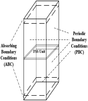
Figure 1: FSS model.
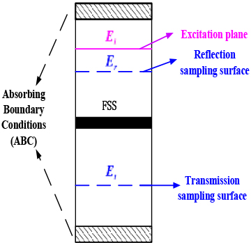
Figure 2: Computation model.
Periodic boundary condition (PBC) is explained in detail in [4]. At present, the common methods to achieve absorbing boundary condition (ABC) mainly include perfectly matched layer (PML), convolution perfectly matched layer (CPML), and uniaxial perfectly matched layer (UPML). When dealing with decay pattern, PML needs to be placed sufficiently far away from the obstacle so that the decay pattern is fully attenuated. However, this will increase the number of grids and reduce the computation speed. Therefore, PML has low efficiency when dealing with decay pattern. CPML is an improved version based on PML [19]. In addition, the parameter ranges of CPML only apply to individual special cases. In actual computations, to satisfy the ABC, a larger range of adjustment coefficients is required, which is not conducive to obtaining results quickly. Therefore, UPML ABCs are adopted in this paper.
Under the excitation of a Gaussian pulse, EM waves propagate along the upper and lower sides of the excitation loading surface. We set the reflection sampling surface and the transmission sampling surface on the upper and lower sides of the FSS structure, respectively. The schematic diagram of the computation model is shown in Figure 2.
It can be seen from Figure 2 that the transmission field E is calculated on the transmission sampling surface, and the total field is calculated on the reflection sampling surface, which includes the reflected field E and the incident field E. Therefore, the expressions for the reflection and transmission coefficients of FSS are shown in the following equation:
| (1) |
where E is the reflected field, E is the transmission field, and E is the incident field.
B. The basic principle of extrapolation method
The basic principle of the extrapolation method is to first calculate the result under the original mesh density (#1). The time step size dt = min(ds)/(4c), where, ds is the space step and c is the wave velocity in space. Then, in order to improve the accuracy, the mesh density is increased to twice the original mesh density, and the result is obtained (#2). At this time, the time step size remains unchanged and still meets the requirements of computational stability. Since the two space divisions before and after are different, but the time step remains the same, the results of these two times can be combined.
For the above two results, a simple extrapolation formula is performed. Extrapolation solution is obtained. This method not only greatly improves the computation accuracy but also reduces the computer memory requirements. The following discussion briefly introduces the reason why the extrapolation method can improve the computation accuracy.
Assuming that f is a function of the independent variable x and time t, and the spacing on the x-axis is h, Taylor expansion of f (x) at t is
| (2) |
Furthermore, Taylor expansion at x is
| (3) |
| (4) |
Similarly,
| (5) |
| (6) |
Besides,
| (7a) |
| (7b) |
Substituting Equation (7) into eqn (6),
| (8) |
Here, f is the results calculated by encrypting the grid (twice the original mesh density) and f is the results under the original mesh density.
It can be seen from Equation (8) that the remaining term is the fourth-order of the space step, so that the extrapolation solution has higher computation accuracy.
C. Hybrid FDTD/extrapolation method
When performing the three-dimensional (3D) numerical computation of the reflection coefficients of the FSS, first, the FDTD/ extrapolation method is used to calculate the EM field, given a certain grid density. Due to space limitations, take the electric and magnetic field components in the x-direction as an example. The updated equations of the electric field and magnetic field are shown in the following equations:
| (9) |
| (10) |
where is the dielectric constant, is the electrical conductivity, is the magnetic permeability, t is the time step, and y and z are space steps, respectively.
Take the electric field component along the x-direction as an example, denoted as . Then, the grid is encrypted. At this time, the calculated result is recorded as . The computation flow chart of the hybrid method combining FDTD and extrapolation method is shown in Figure 3.
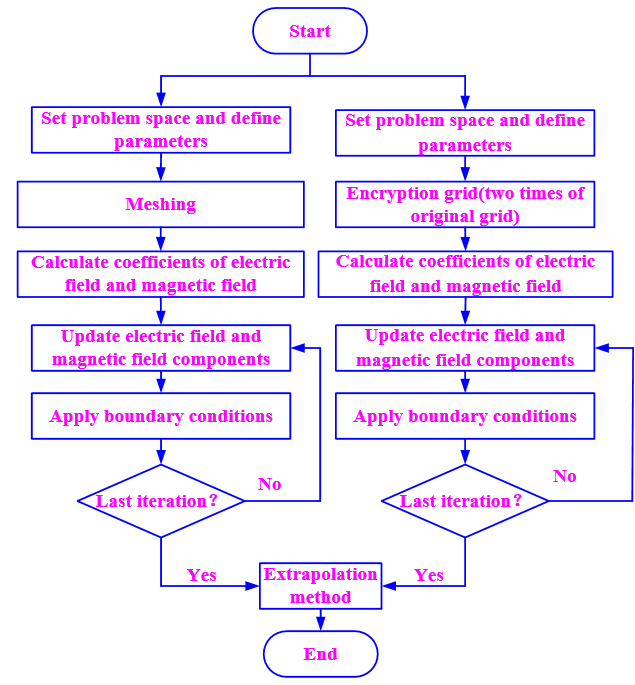
Figure 3: The computation flow chart of the hybrid method.
From Equation (8), the extrapolation solution is
| (11) |
D. Cascading
The scattering matrix for each independent periodic structure is calculated. Then, all independent scattering matrices are cascaded. Figure 4 shows the schematic diagram of the N-layer FSS. In addition, when the spacing is small (d/ 1), the propagation constant of the cross-polarization is negative imaginary, and the field decays exponentially away from the FSS. Thus, the quantities of practical interest are the reflection coefficient of the main polarization, and the cross-polarization is ignored. The reflection coefficients of a single-layer FSS are calculated using the method in Section II-C. Then, the single-layer scattering matrix according to the computation results of the reflection and transmission coefficients is deduced by the following expression:
| (12) |
From Equation (12), the expression of the cascaded transmission matrix can be obtained as
| (13) |
When the second port is open circuit, A is the ratio of the voltage of the first port to the voltage of the second port and C is the ratio of the current of the first port to the voltage of the second port; when the second port is short circuit, B is the ratio of the voltage of the first port to the current of the second port and D is the ratio of the current of the first port to the current of the second port.
After cascading, the reflection and transmission coefficients of the multi-layer FSS turn out to be
| (14) |
| (15) |
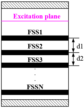
Figure 4: The N-layer FSS.
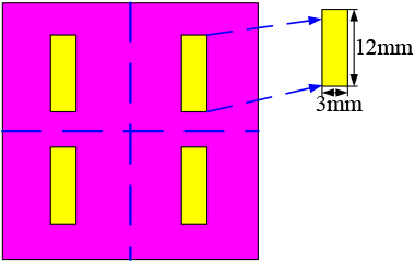
Figure 5: Structure model.
III. VERIFICATION OF COMPUTATION METHOD
A. Verification of hybrid method
In order to test the accuracy of the hybrid method, a dielectric plate and FSS with infinite periodic structure are considered. The period of the dielectric plate along the x-axis and y-axis is 15 mm, its thickness is 6 mm, and the relative permittivity is 4.3. Metal patch with a length of 12 mm and a width of 3 mm on the surface of the above-mentioned dielectric layer. The model is shown in Figure 5. A Gaussian pulse excitation with the center frequency of 8 GHz is applied to the structure. The reflection coefficient comparison chart is shown in Figure 6(a) and (b), respectively. The extrapolated solution of Figure 6(a) is calculated from the grid size r = 1.5 mm and r = 3 mm. Figure 6(b) is calculated from the grid size r = 0.3 mm and r = 0.6 mm. Tables 1 and 2 show the comparing results of the dielectric plate and the FSS. The expression of maximum relative error is
| (16) |
where R is the simulation result (CST) and R is the computational result.
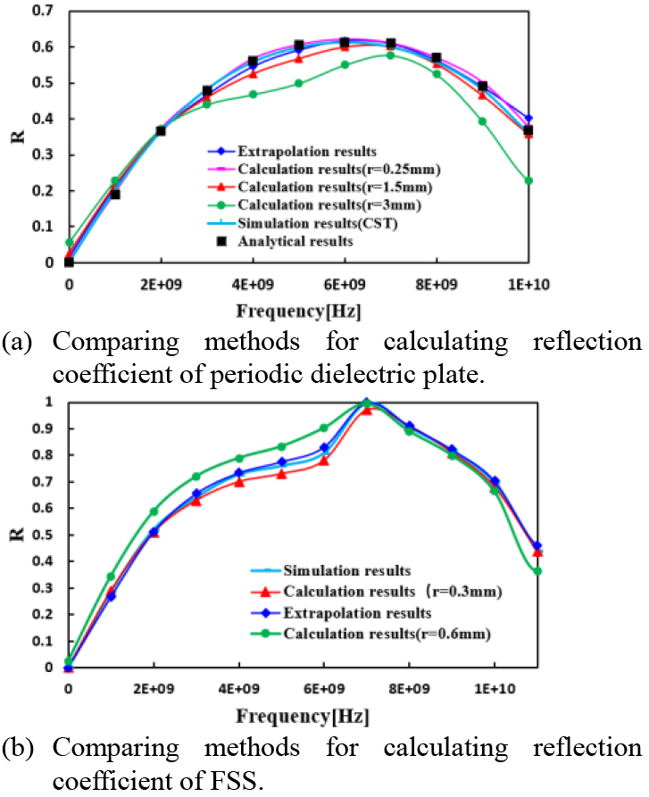
Figure 6: Comparison chart of computation results.
Table 1: Comparison of the efficiency (dielectric plate)
| Spacing | Running time | Memory requirement | Maximum relative error | |
|---|---|---|---|---|
| FDTD | 3 mm | 4.906 s | 7306 M | 17.5% |
| 1.5 mm | 8.342 s | 7322 M | 7.1% | |
| 0.25 mm | 858.66 s | 8476 M | 1.4% | |
| MM | Running time | Memory requirement | Maximum relative error | |
| 12.436 s | 7886 M | 1.5% | ||
| CST | 120.86 s | 16998 M |
Table 2: Comparison of the efficiency (FSS)
| Spacing | Running time | Memory requirement | Maximum relative error | |
|---|---|---|---|---|
| FDTD | 0.6 mm | 233.5 s | 7406 M | 7.05% |
| 0.3 mm | 1025.1 s | 12,853 M | 5.9% | |
| MM | Running time | Memory requirement | Maximum relative error | |
| 1256.2 s | 14,855 M | 1.8% | ||
| CST | 4267.8 s | 266,761 M |
It can be seen from Figure 6 that the denser the grid, the higher the computation accuracy of the FDTD. However, if the computation accuracy is improved by encrypting the grid, the memory requirement will be greatly increased, thus reducing the computation speed. In engineering applications, not only high computation accuracy but also fast computation speed is required. Therefore, the method needs to be improved. In addition, it can be seen from Figure 6 that the sparser the grid, the worse the computation accuracy of the FDTD, but the extrapolation solution can greatly improve the computation accuracy without increasing the grid density.
It can be seen from Tables 1 and 2 that within the range of errors permitted, the computation speed of the hybrid method is superior. The proposed method can greatly save the computation time and improve accuracy of the EM properties of the FSS.
B. Verification of cascade method for multi-layer FSS
The above method is extended to the computation of EM characteristics of multi-layer FSS. The two-layer FSS structure is considered. The distance between the two-layer structures is 24 mm, and the structural parameters of the FSS are the same as those in Section III-A. The computation results are shown in Figure 7.
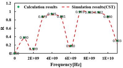
Figure 7: Reflection coefficient comparison diagram.
As shown in Figure 7, the hybrid method is used to calculate the reflection coefficient of the multi-layer FSS. The calculated result is very close to the simulation result, and the error between the two is small. In addition, the matrix cascading technology can greatly reduce the number of grids and the computer memory requirements and increase the computation speed. Through comparison, we can see that the computation method in this paper is correct and reasonable.
IV. EXAMPLES AND ANALYSIS
A. Computation of FSS with different patches
The structural parameters of the dielectric layer are the same as above, and the length and width of the upper patch are both 12 mm. And the length and width of the lower patch are 12 and 3 mm, respectively. The 3D model is shown in Figure 8, the Gaussian excitation source is the same as above, and the computational result is shown in Figure 9. The FSS with different patch geometries are shown in Table 3.
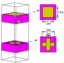
Figure 8: Structure model.
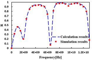
Figure 9: Computation results.
Table 3: Comparing methods
| Running time | Occupy memory | |
|---|---|---|
| MM | 2625.1 s | 26,988 M |
| CST | 8468.6 s | 47,899 M |
From Table 3, we can see that the computation speed of the hybrid method is superior. In the same way, the algorithm proposed in the paper is suitable for the computation of EM characteristics of the FSS with different patch geometry.
B. Factors influencing reflection coefficient
1) The impact of dielectric constant
The reflection coefficient of the FSS is closely related to the dielectric constant of the dielectric layer. Suppose the structural parameters of FSS are the same as Section III-A. Keep the excitation source and the length and width of the dielectric layer unchanged. Change the dielectric constant of the dielectric layer and observe the change of reflection coefficient. The computed reflection coefficients are shown in Figure 10.
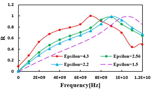
Figure 10: The effect of dielectric constant on results.
From Figure 10, within 1-5 of dielectric constant, it can be concluded that the resonance frequency decreases with increasing dielectric constant. It can be seen that the dielectric layer mainly affects the resonant frequency. Therefore, by loading FSS, the transmission frequency of the radome can be adjusted effectively.
2) The impact of patch geometry parameters
The reflection coefficient of the FSS is not only closely related to the dielectric constant but also tightly dependent on the structure of the patch. As in the previous case, keeping the excitation source, the size of the dielectric layer, and the material characteristics unaltered, and changing the patch geometry to square, monopole, and cross shape, the computed results are shown in Figure 11.
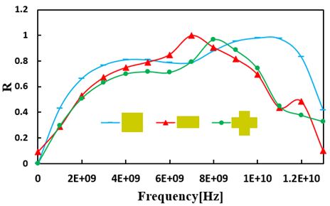
Figure 11: The effect of patch geometry on results.
As shown in Figure 11, the resonance frequency depends on the patch geometry; the larger the patch geometry covers the area of the dielectric layer, the larger the resonance point of frequency. It provides an important reference basis for the design of passband range of the FSS.
V. CONCLUSION
1. In this paper, a hybrid method combining FDTD, extrapolation, and cascading is proposed to compute the reflection coefficient of the multi-layer FSS. By means of an example, it is shown that the algorithm has the advantages of increasing the computation speed and accuracy, and reducing the computer memory.
2. The EM characteristics of the FSS are computed. The results show that the proposed method in this paper is also applicable to multi-layer FSS with different patch geometry.
3. Within 1-5 of dielectric constant, the resonance frequency decreases with increasing the dielectric constant.
4. The resonance frequency depends on the patch geometry. The larger the area of the patch geometry covering the dielectric layer, the larger the resonance frequency; a property which provides an important reference for the design ofthe FSS.
ACKNOWLEDGMENTS
This work was supported by the National Natural Science Foundation of China under Grant 61871405.
REFERENCES
[1] D. M. Guo, Y. W. Sun, and Z. Y. Jia, “Methods and research progress of high performance manufacturing,” journal of mechanical engineering. vol. 51, no.11, pp. 119-134, 2014.
[2] D. J. Kozakoff, Analysis of Radome Enclosed Antennas. Boston: Artech House, 2009.
[3] B. L. Cannon, and J. W. Jordan, “Integration of an equivalent aperture method into full-wave electromagnetic simulation of airborne radomes,” Journal of the Applied Computational Electromagnetic Society, vol. 31, no. 5, pp. 473-480, 2016.
[4] R. Panwar, and J. R. Lee, “Progress in frequency selective surface-based smart electromagnetic structures: a critical review,” Aerospace Science & Technology, vol. 66, no. 1, pp. 216-234, 2017.
[5] Q. Chen, L. Chen, J. Bai, and Y. Fu, “Design of absorptive frequency selective surface with good transmission at high frequency,” Electronics Letters, vol. 51, no. 12, pp. 885-886, 2015.
[6] W. Wu, X. Liu, K. Cui, Y. Ma, and Y. Yuan, “An ultrathin and polarization-insensitive frequency selective surface at Ka-band,” IEEE Antennas and Wireless Propagation Letters, vol. 17, no. 1, pp. 74-77, 2018.
[7] K. Payne, K. Xu, and J. H. Choi, “Generalized synthesized technique for the design of thickness customizable high-order bandpass frequency-selective surface,” IEEE Transactions on Microwave Theory and Techniques, vol. 99, no. 1, pp. 1-11,2018.
[8] K. Zhang, W. Jiang, J. Ren, and S.-X. Gong, “Design of frequency selective absorber based on parallel LC resonators,” Progress in Electromagnetics Research, vol. 65, no. 1, pp. 91-100, 2018.
[9] S. Narayan, G. Gulati, B. Sangeetha, and R. U. Nair, “Novel metamaterial-element-based FSS for airborne radome applications,” IEEE Transactions on Antennas and Propagation, vol. 66, no. 9, pp. 4695-4707, 2018.
[10] M. Bai, B. Liang, and H. Ma, “An efficient FDTD algorithm to analyze skewed periodic structures impinged by obliquely incident wave,” Journal of the Applied Computational Electromagnetic Society, vol. 30, no. 10, pp. 1068-1073,2015.
[11] N. Liu, Study on rapid design method for high performance frequency selective surface radome. Department of Mechanical Engineering, Dalian university of technology, Ph.D, Spring 2019.
[12] K. Fan, Design and research on active FSS radome. Department of Electronic Information Engineering, Nanjing university of aeronautics and astronautics, MS, Spring 2014.
[13] H. Y. Chen and S. H. Wen, “An empirical formula for resonant frequency shift due to Jerusalem-cross FSS with substrate on one side,” Applied Computational Electromagnetic Society, vol. 30, no. 7, pp. 730-737, 2018.
[14] K. S. Feng, C. J. Xie, and J. D. Xu, “Finite element method analysis of frequency selective characteristics of periodic structure of medium,” Journal of Microwaves, vol. 24, no. 1, pp. 1-8,2008.
[15] M. Jin and M. Bai, “On the transmitted beam degradation through FSS in the working band by plane-wave spectrum computation and evaluation,” Applied Computational Electromagnetic Society, vol. 31, no. 9, pp. 1135-1143, 2016.
[16] P. Monk, “Sub-gridding FDTD schemes,” Applied Computational Electromagnetic Society, vol. 11, no. 1, pp. 37-46, 1996.
[17] C. M. Chen, “Extrapolation of triangular linear element in general domain,” Numerical Mathematics A Journal of Chinese, vol. 3, no. 1, pp. 1-6, 1989.
[18] Y. M. Li, “A new algorithm for improving computation precision in finite difference time domain,” Proceedings of the 10 national conference on electrical engineering mathematics, 2005.
[19] Z. Y. Yu, The Finite-Difference Time-domain Method for Electromagnetics with MATLAB Simulations. National defense industry press,2012.
BIOGRAPHIES

Yangyang Wang was born in 1990. She received the Ph.D. degree from Chongqing University, Chongqing, China, in 2020.
She is currently working with the National Digital Switching System Engineering and Technological Research Center, Zhengzhou, China. Her current research interests include antenna and radome analysis and design, computational electromagnetics, etc.

Dongfang Zhou was born in 1963. He received the Ph.D. degree from Zhejiang University, Hangzhou, China, in 2005.
He is currently working with the National Digital Switching System Engineering and Technological Research Center, Zhengzhou, China. His current research interests include antenna and propagation, radio frequency and microwave circuits and systems, and high power microwave and radome.

Qikun Liu was born in 1985. He received the Ph.D. degree from PLA Strategic Support Information Engineering University.
He is currently working with the National Digital Switching System Engineering and Technological Research Center, Zhengzhou, China. His current research interests include antenna and propagation, radio frequency, and radome.

Dewei Zhang received the Ph.D. degree from the National Digital Switching System Engineering and Technological Research Center, Zhengzhou, China, in 2005.
He is currently working with the National Digital Switching System Engineering and Technological Research Center. His current research interests include RF/microwave devices, such as antennas, filters, and power amplifier, for wireless communications, and radar systems.
ACES JOURNAL, Vol. 37, No. 2, 176–183.
doi: 10.13052/2022.ACES.J.370205
© 2021 River Publishers