Analysis of Nonlinear Characteristics and the Factors Affecting the Operation of the Active Magnetic Bearings Rotor System Considering Alford Force
Siyuan Zhang, Jin Zhou, Xiaoming Han, and Yanchao Ma
1College of Mechanical and Electrical Engineering, Nanjing University of Aeronautics and Astronautics, Nanjing 210016, China
zhangsiyuan@nuaa.edu.cn, hanxiaoming@nuaa.edu.cn, mayanchao@nuaa.edu.cn
2National Key Laboratory of Science and Technology on Helicopter Transmission, Nanjing University of Aeronautics and Astronautics, Nanjing 210016, China
zhj@nuaa.edu.cn
Submitted On: October 28, 2021; Accepted On: January 26, 2022
Abstract
Based on a test rig supported by active magnetic bearings (AMBs), this paper focuses on the study of the nonlinear dynamic characteristics and the factors affecting the operation of a rotor system under the coupling of magnetic bearing force and Alford force. In order to solve the nonlinear dynamic response of rotor system, a dynamic equation of the rotor which introduces Alford force and the electromagnetic force of the AMBs controlled by PID is established. By changing the control parameters (k and k), operation parameters (rotational speed), and structural parameters (clearance between impeller and volute), the equation is solved by using RungeKutta method. The results show that the rotor system exhibits complex nonlinear dynamic characteristics under the coupling action of Alford force and magnetic bearing force. The rotor system appears different dynamic behaviors such as single period, multi multi-period, and quasi quasi-period when changing the control parameters. Among all the control parameters, adjusting k is more effective to ensure system stability. The amplitude of rotor increases from 8.2 m to 11.9 m with the increase of speed from 6000 rpm to 10,000 rpm, while that decreases from 9.6 m to 8.2 m with the increase of clearance between impeller and volute from 1mm to 4 mm. Therefore, under the influence of Alford force, apart from the control parameters, the operation parameters and structural parameters of magnetic bearings also affect the operation of the rotor system supported by the AMBs.
Keywords: Active magnetic bearings, Alford force, Rotor rotor dynamics, Nonlinearnonlinear.
I. INTRODUCTION
The stable operation of rotor system is the premise of normal operation of rotating machinery. However, because of the manufacturing and assembly problems, the impeller and volute are relatively eccentric, thus leading to the uneven distribution of tip clearance unevenly distribution as well as the difference in blade efficiency and pressure distribution around the circumference. According to Bernoulli principle, the blade with small clearance is more efficient and dose does more work and, therefore, receives more aerodynamic load. In consequence, apart from the resultant torque, a transverse force acting on the impeller axis which increases with the increase of impeller eccentricity is generated by the circumferential aerodynamic force. The transverse force is a self-excited force of the rotor which may eventually cause the instability of the rotor. Consequently, it is necessary to explore the influence of this force coupling on the rotor system.
GE found this phenomenon in the test of a gas turbine. The vibration was not effectively eliminated by dynamic balance method but finally solved by changing the structure. At that time, people did not pay more attention to this phenomenon. Until 1958, Thomas first raised this problem in the study of the stability of steam turbine [1]. Alford studied this problem and established a mechanical model [2]. Therefore, this force is usually called Alford force. Since then, many scholars have studied Alford force. Cheng et al. who combined rolling bearing force with Alford force and used the RungeKutta method to solve the dynamic equations of the system found that excessive bearing clearance and rotor eccentricity will reduce the stability of the system [3]. Jung et al. did a limit-cycle analysis of auto-balancer system considering Alford force. The results showed that for certain combinations of bearing parameters and operating speeds, the global asymptotic stability of the synchronous balanced condition can be guaranteed [4]. Yada et al. analyzed the open/close nozzle mode and the open/close ratio of the symmetrical part of the partial intake turbine in the turbopump of the rocket engine. It is found that the Alford force varies with the rotation angle at a certain opening/closing ratio and put forward the universal rules to provide guidelines for follow-up research [5]. Taking the flexible shaft and elastic disk rotor system as the research object, Yang et al. established the vibration differential equation with the modal synthesis method and solved the equation by using the RungeKutta method. The results showed that the increase of speed and disk radius will lead to the increase of rotor response, which can help to improve the stability of the system by adjusting the support position [6]. Li et al. analyzed the impact of nonlinear coupling factor and blade-bending vibration to dynamic characteristics of rotor-bearing system and the results indicated that the Alford force caused by blade tip clearance makes the motion state of the system more complex [7].
Based on the rolling bearing rotor system, many scholars have studied the factors that affect the operation of rotor system considering Alford force. However, in recent years, with the application and development of electromagnetic technology, permanent magnet generator [8–10], maglev planar motor [11–13], and magnetic bearings [14–16] have been widely concerned because of its advantages of no friction, high speed, and long life. In addition, active magnetic bearings (AMBs) that can be actively controlled has have been successfully applied in many industrial products [17]. Therefore, it is necessary to study the factors affecting the stability of the rotor system supported by the AMBs under Alford force. There are few researches on it, nevertheless. Wang et al. who established the finite element model of the coupling of magnetic bearing force and Alford force under PID control algorithm used the Newmark- method to solve the dynamic response of the rotor system. The results showed that under the action of magnetic bearing force and Alford force, the system shows complex dynamic characteristics and the control parameters have great influence on the characteristics of rotor system. But, this paper only does the simulation research [18].
In this paper, an AMB test rig is taken as the research object, a dynamic equation which considers the coupling effect of Alford force and magnetic bearing force under the PID controller is established, and the rotor response is solved with the RungeKutta method. The results show that after considering Alford force, the system has significant nonlinear characteristics. Meanwhile, by changing the control parameters (k and k), operating parameters (rotational speed), as well as structural parameters (clearance between impeller and volute), the characteristics of the system have changed greatly. It shows that different from the traditional bearing, the magnetic bearing should take not only structural characteristics but also the control parameters into account.
II. MODELING OF THE AMBs ROTOR SYSTEM CONSIDERING ALFORD FORCE
A. The AMBs rotor system model
A typical AMB rotor system structure is shown in the Figure 1. It is limited to 5 five degrees of freedom by AMBs and driven to rotate by motor.
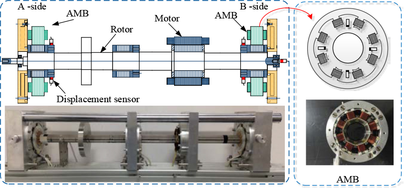
Figure 1: Active magnetic bearing rotor system structure.
The electromagnetic force produced by an electromagnet in a magnetic bearing can be expressed as
| (1) |
The magnetic bearing adopts differential arrangement in one degree of freedom and the resultant force under the action of a pair of magnets is:
| (2) | ||
The Taylor expansion is carried out at i= 0, x = 0 and the higher order term is ignored, . The magnetic bearing force on the rotor can be expressed as:
| (3) | ||
where is the vacuum permeability, A is the area of a single magnetic pole, N is the total number of turns of the coil on a pair of magnetic poles, C is the unilateral air gap when the rotor is at the magnetic center, I is the coil bias current, i is the coil control current, k is the displacement stiffness coefficient, and k is the current stiffness coefficient.
B. Alford force model
Many scholars have focused on the modeling of Alford force. The first model given by Thomas is as follows:
| (4) |
where m is the total gas flow, is the pressure coefficient, u is the tangent speed at the center of the blade, is the local efficiency loss, is the tip clearance, and e is the eccentricity.
Alford made a further study and established the model as:
| (5) |
where, T is the torque on the impeller, D is the diameter at the center of the blade, H is the blade height, is the efficiency coefficient, and e is the eccentricity.
However, their models have some limitations. First, their models are based on the local efficiency loss of impeller. What’s more, it is difficult to get some parameters of the model. In Thomas’ model, is irregular and difficult to calculate. In Alford’s model, similar to the correction factor, is a variable value that can be adjusted to meet the matching between theory and experiment by adjusting that value. Since then, many scholars have revised and improved the Alford force model [19–20]. Among them, based on fluid mechanics and momentum theorem, Chai et al. combined the impeller structure parameters to carry out theoretical modeling and used numerical methods to verify the reliability of the model [21]. This paper applies the model established by Chai et al. The details are as below follows:
| (6) | ||
where e is the eccentricity, R is the tip radius, R is the root radius, is the inlet angle, is the outlet angle, is the airflow density, is the speed coefficient, is the average tip clearance, V is the inlet speed, and f, f are the component forces of the Alford force in the x and y directions.
C. System dynamics equation
Alford force and magnetic bearing force are substituted into the rotor system and the system dynamics equation is as follows:
| (7) |
The AMBs are different from rolling bearings as the control algorithm also affects the support characteristics of the AMBs. This paper adopts PID controller which is widely used in industry, and the bearing force under the PID controller can be expressed as:
| (8) |
where m is the rotor mass, and k, k, and kare the proportional, integral, and differential coefficients.
Formulae (8) and (6) are substituted into eqn (7) and the dimensionless transformation is introduced to facilitate computation.
Taking , formula (7) is changed into:
| (9) |
In formula (9):
Transform formula (9) into matrix form:
| (10) |
Due to the strong nonlinear characteristics of the system, the RungeKutta method is used to solve the dynamics equation of the system and the results are analyzed.
III. SYSTEM CHARACTERISTIC ANALYSIS
In order to explore the influence of Alford force, simulation is carried out. In the simulation, the magnetic bearing rotor system and impeller parameters are shown in the Table 1.
Table 1: Parameters of magnetic bearing and impeller
| Mass | m | 14.56 | kg |
| Current stiffness | k | 338.54 | N/A |
| Displacement stiffness | k | 2.502e6 | N/m |
| Tip radius | R | 29 | mm |
| Root radius | R | 7.5 | mm |
| Inlet angle | 25 | ||
| Outlet angle | 30 |
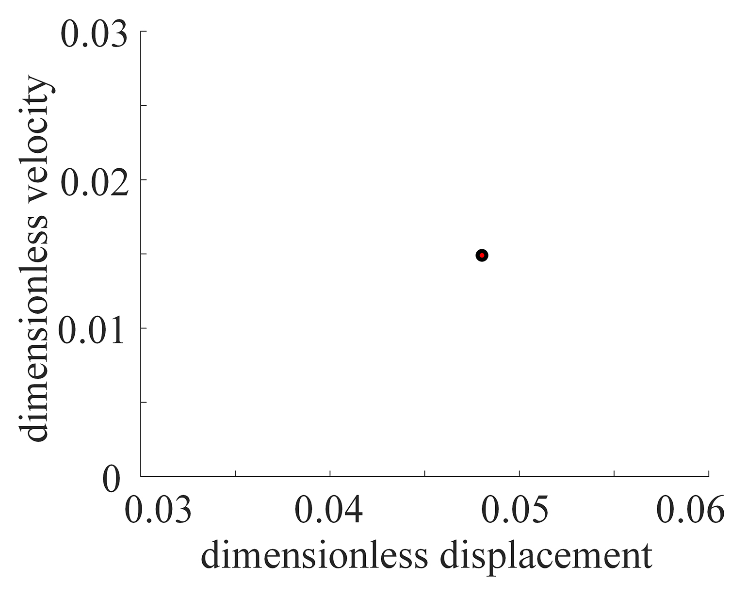
Figure 2: Dynamics behavior of the system.
The Poincare map is obtained according to the solution of the motion equation. As shown in Figure 2, without considering the influence of Alford force, the system is characterized by a single point on Poincare map at 100 Hz, and it shows that the system behaves as a typical single period motion. After introducing Alford force, the Poincare map shows a bunch of outward divergent points and the system is in multi-period motion. When the rotating speed is increased to 500 Hz, the Poincare map is similar to that at 100 Hz, but the divergence is stronger than that at 100 Hz, which indicates that the system is in multi-period motion and with a stronger non-linearity. Fast Fourier transform (FFT) analysis at the speed of 500 Hz shows that apart from the main frequency, there is still a frequency of 204 Hz which verifies the existence of Alford force.
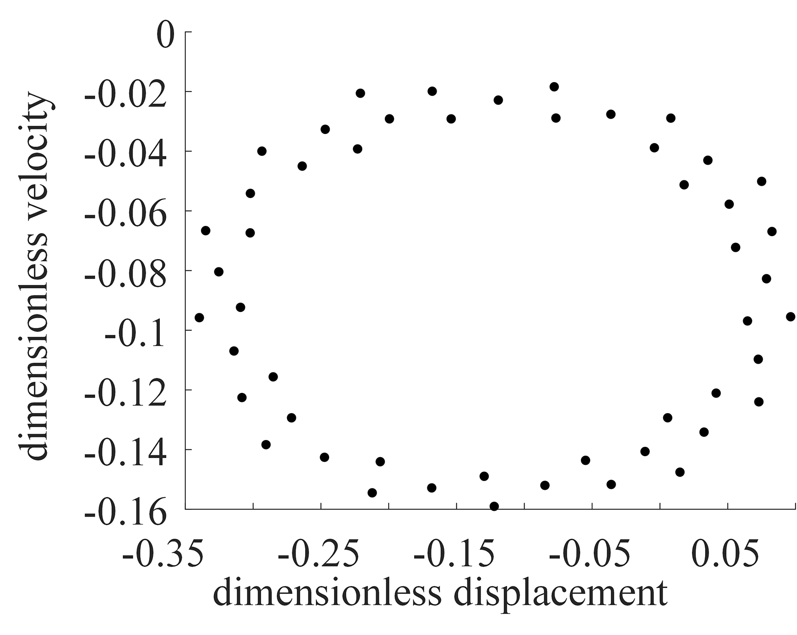
Figure 3: Dynamics behavior of the system underdifferent k.
As mentioned above, the supporting characteristics of the AMBs can be changed by adjusting control parameters. In this paper, with the adoption of the PID controller. k and k are expressly explored as they have a great influence on the system characteristics. Figure 3 is the Poincare map and phase trajectory diagram of the system when k is 0.0015 and 0.015, respectively. The Poincare map appears as a closed ellipse and the phase trajectory is relatively miscellaneous when k is 0.0015. At this time, the whole system is in quasi-periodic motion. When k is 0.015, the Poincare map and the phase trajectory are single, which means the system is in single periodic motion. The results show that the system runs more stably with the increase of k. This is because in the AMBs rotor system, adjusting k is equivalent to changing system damping which can effectively improve the stability of system operation.
Figure 4 is the Poincare map as well as the phase trajectory diagram of the system when k is 1 and 3, respectively. Compared with k, k has less influence on the system. Whether k is 1 or 3, the Poincare maps of the system are divergent points and the phase trajectories are multiple mixed lines. In this case, the system is in multi-periodic motion. The small influence of k is due to the fact that in the AMBs rotor system, adjusting k is equivalent to changing the system stiffness.
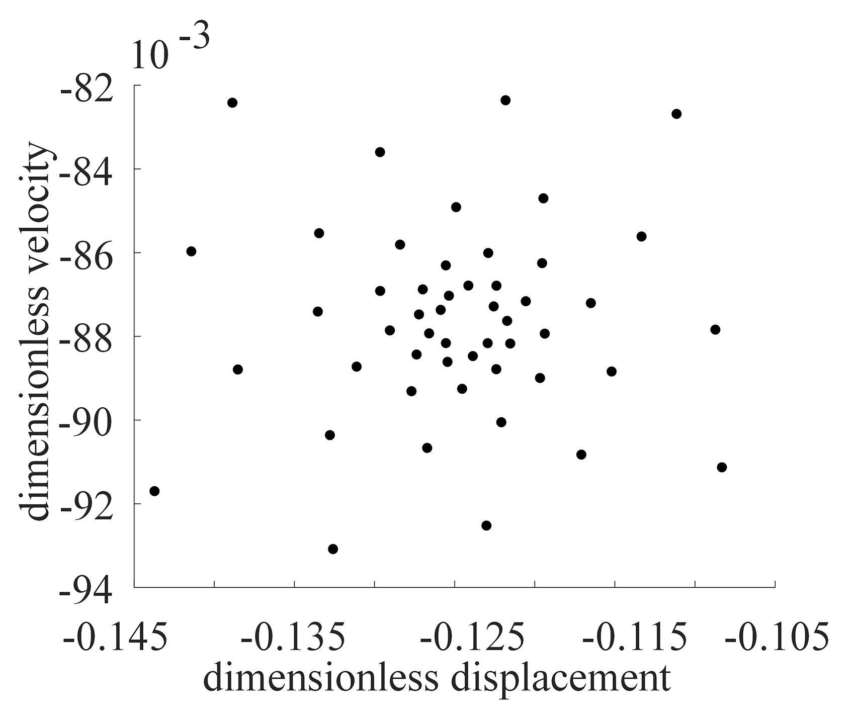
Figure 4: Dynamics behavior of the system underdifferent k.
IV. EXPERIMENTAL SETUP
In order to verify the accuracy of the above analyses, an AMBs rotor system test rig is used to conduct the experiment. The experimental setup is shown in Figure 5.
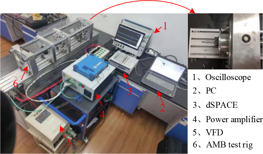
Figure 5: Experimental setup.
First, the experiment is conducted without installing the volute. Assuming that the circumference of the impeller is a uniform field without differential pressure, so no influence of Alford force will be considered. As shown in Figure 6, the amplitude response of the rotor at a speed of 100 Hz in this state is obtained. Then through installing the volute to create Alford force, the amplitude response of the rotor in this state is obtained. Comparing that with the amplitude response of the rotor without volute, the results are shown in Figure 7. It shows that the amplitude of the rotor increases by about 2 m within the range of all running speeds after installing the volute considering the effect of Alford force.
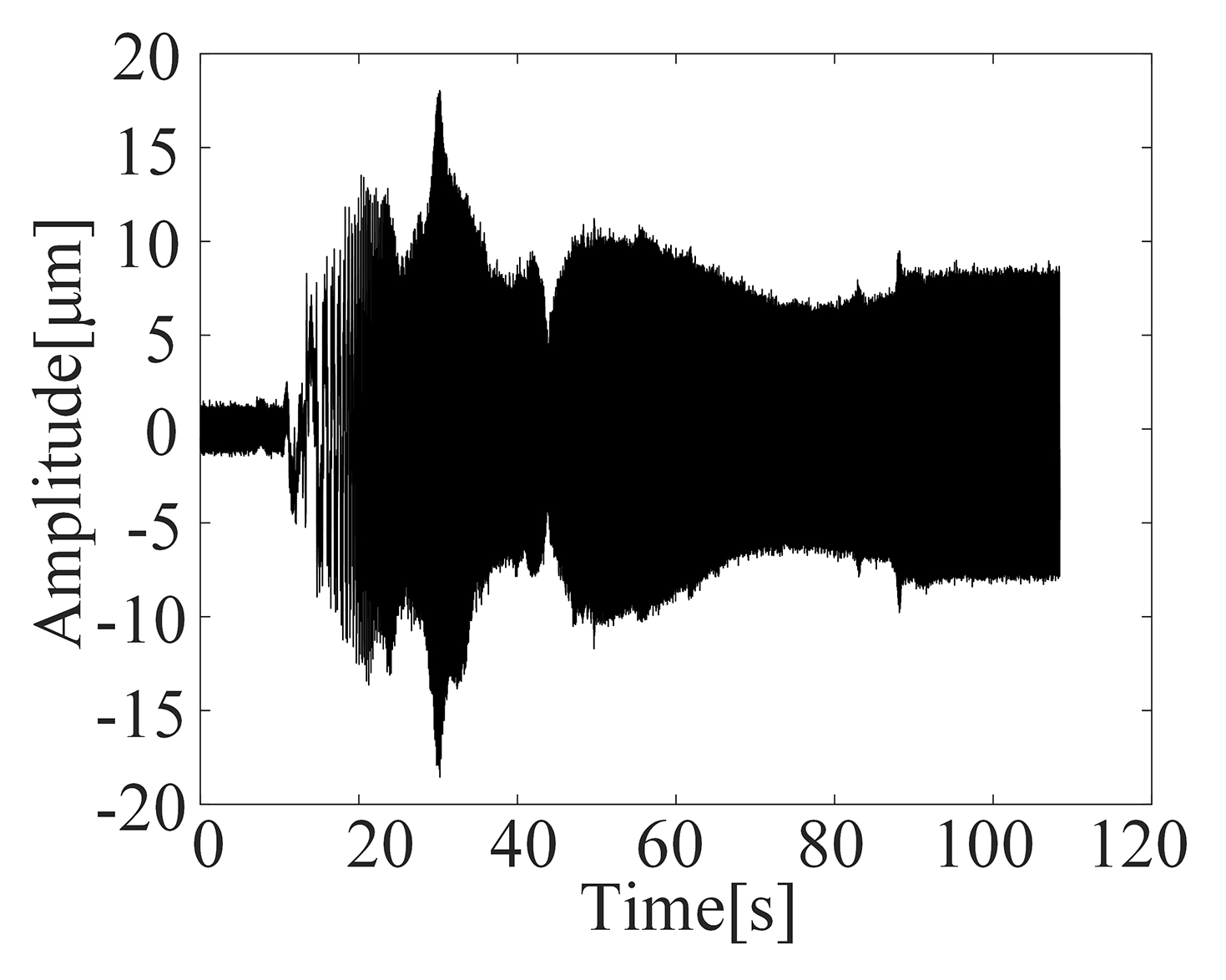
Figure 6: Rotor response without the Alford force.
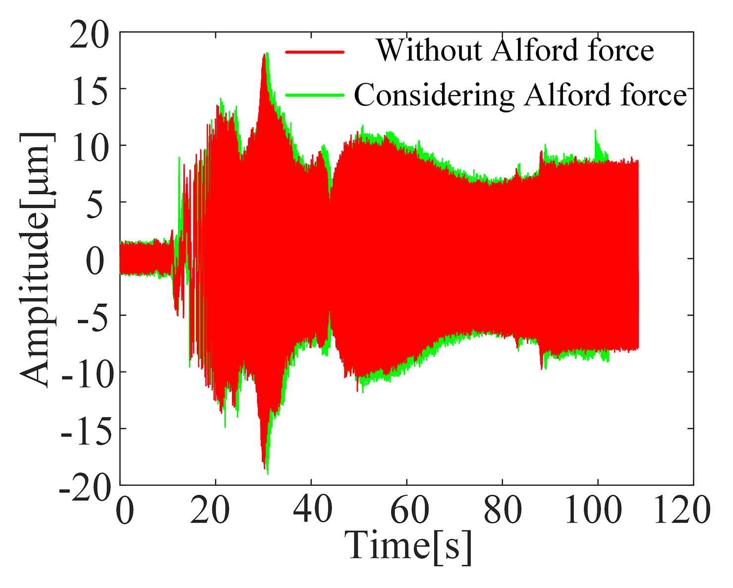
Figure 7: Comparison of rotor response with and without Alford forces.
ISO 14839-2 defines the vibration displacement level of a magnetic bearing rotor system under steady conditions [22]. In Figure 8, x and y are the maximum amplitudes measured by the sensor in the radial direction, and D is the maximum radial displacement of the rotor.
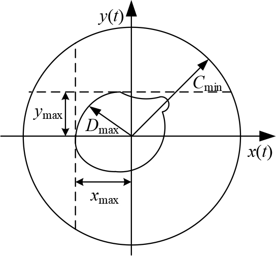
Figure 8: Rotor orbit of vibration displacement.
So,
| (11) |
where x(t), and y(t) is are the rotor position coordinates.
Table 2: Recommended criteria of zone limits
| A | A 0.3 |
|---|---|
| B | |
| C | |
| D |
C means the gap between protective bearing and the rotor. In this paper, C mm.
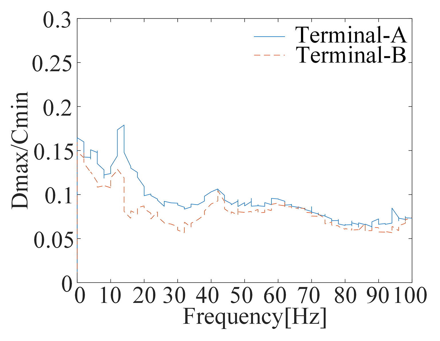
Figure 9: Rotor vibration level.

Figure 10: Rotor response under different rotational speeds.
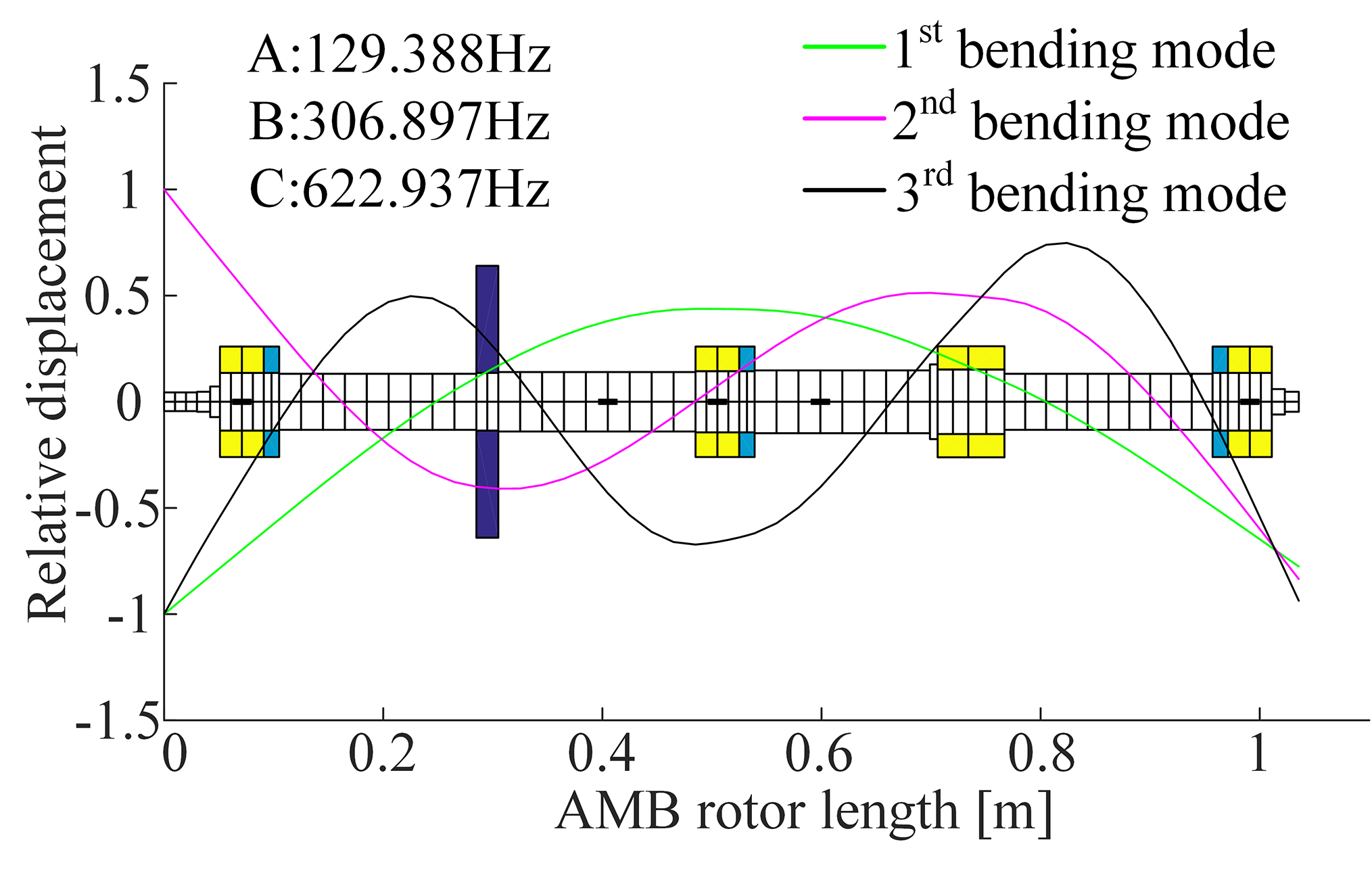
Figure 11: Rotor modal analysis.
Based on the above testing principles and methods, the vibration displacement level curve of both ends of the rotor are obtained, as shown in Figure 9. With the effect of impeller, the amplitude of terminal A is larger than B.
As shown in Table 2, the ISO 14839-2 standard defines the level of vibration displacement of a rotor in a magnetic levitation system, where .
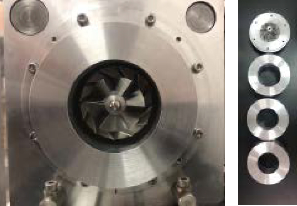
Figure 12: Sleeve with different clearance.
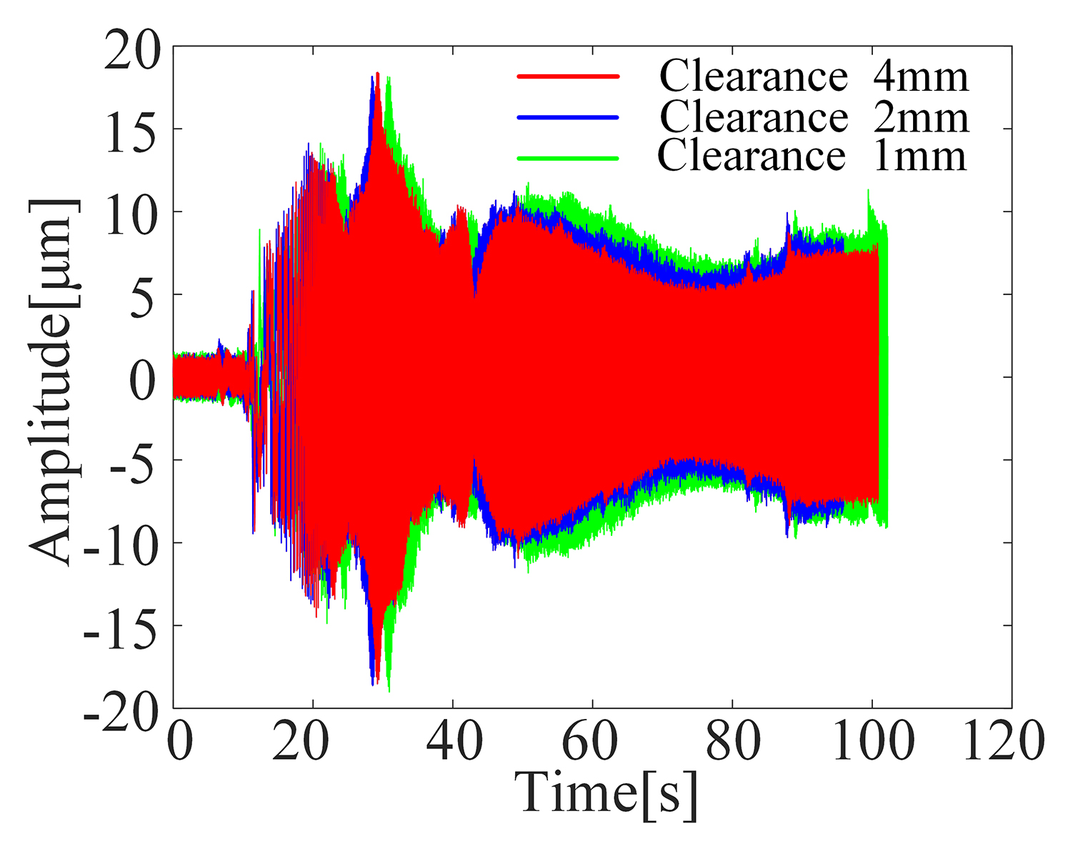
Figure 13: Rotor response under different clearance.
Combined with the recommended level of standards in the table, the amplitude ratio of vibration displacement at both ends is less than 0.3, indicating that the rotor vibration displacement level of the test rig is within level A, which provides a guarantee for subsequentresearch.
Figure 10 shows the amplitude of the rotor considering Alford force at different speeds. It can be seen that the amplitude of the rotor increases from 8.2 m to 11.9 m with the increase of the rotating speed from 6000rpm to 10,000 rpm. While at 8000 rpm, the amplitude of the rotor is the largest, reaching 14.7 m, because 8000 rpm is close to first-order frequency. The modal shape and frequency of the rotor in the free-free state are obtained by simulation, as shown in Figure 11, and the first-order mode frequency is 130 Hz, which verified the above analysis.
Alford force is caused by the clearance difference. In this paper, sleeves with different inner diameters are machined to produce different Alford forces and the structure is shown in the Figure 12. The response of the rotor with different clearances is obtained and shown in the Figure 13 which reveals that with the increase of the clearance from 1mm to 4 mm, the amplitude of the rotor decreases from 9.6 m to 8.2 m. This means that a larger gap produces a smaller Alford force. Due to the large clearance, the flow field between the cylinder and impeller is more uniform and the pressure difference is smaller, thus leading to a smaller Alford force.
V. CONCLUSION
Taking an AMBs rotor system test rig as the research object, this paper not only analyzes the dynamic characteristics of the rotor system under the coupling action of Alford force and magnetic bearing force but also explores the factors affecting the operation of the system. The results reveals that the rotor system shows more complex characteristics when considering Alford force. The specific conclusions are as follows:.
1) Without considering Alford force, the whole system behaves in a typical single period motion. At the same time, the test rig meets the level-A standard without the influence of Alford force, which guarantees the follow-up research. After considering the Alford force, the whole system behaves in a multi-period motion, which indicates that it has strong nonlinear characteristics.
2) It can be concluded that when the control parameters k and k, the rotational speed, and the clearance between impeller and volute are changed, k has little influence on the rotor operation and k of which selection should be paid more attention to when setting the parameters is more obvious. In addition, the coupling effect is more obvious with the increase of speed, ; therefore, when the system operates at high speed, we need to pay more attention. Last but not least, the clearance between impeller and volute also affects the state of the system. With the increase of clearance, the effect is relatively reduced. In further design, the effect can be reduced by increasing the clearanceappropriately.
ACKNOWLEDGMENT
This work was supported in part by National Key Laboratory of Science and Technology on Helicopter Transmission (under Grant No. HTL-A-20K03) and in part by the National Nature Science Foundation of China (under Grant No. 52075239).
REFERENCES
[1] H. J. Thomas, “Unstable oscillations of turbine rotors due to steam leakage in the sealing glands and the buckets,” Bullet in Scientifique A.J.M, vol. 71, pp. 223-236, 1958.
[2] J. S. Alford, “Protecting turbomachinery from self-excited whirl,” ASME Journal of Engineering for Power, no. 05, pp. 333-344, 1965.
[3] M. Cheng, G. Meng, and B. Y. Wu, “Effect of Alford force and ball bearing on dynamic characteristics of a rotor system,” Journal of Vibration and Shock, vol. 30, no. 12, pp. 164-168, 2011.
[4] D. Y. Jung and H. A. DeSmidt, “Limit-Cycle analysis of planar Rotor/Autobalancer system influenced by Alford force,” Journal of Vibration & Acoustics, vol. 138, no. 2, pp. 021018.1-021018.14, 2016.
[5] K. Yada, M. Uchiumi, and K. I. Funazaki, “Thomas/Alford force on a Partial-Admission turbine for the rocket engine turbopump,” Journal of Fluids Engineering, vol. 141, no. 01, 2018.
[6] W. Yang, H. Yuan, L. Hui, and K. Zhang, “Dynamic analysis of flexible shaft and elastic disk rotor system based on the effect of Alford force,” Shock & Vibration, no. PT.2, pp. 3545939.1-3545939.13, 2019.
[7] B. Li, L. Zhang, and Y. Y. Cao. “Dynamic characteristic analysis for Rotor-bearing system with Alford force considering blade vibration,” Journal of Ship Mechanics, vol. 24, no. 1, 2020.
[8] I. Ahmad, J Ikram, M. Yousuf, R. Badar, S. S. H. Bukhari, and J.-S. Ro, “Performance improvement of Multi-rotor axial flux vernier permanent magnet machine by permanent magnet shaping,” IEEE Access, vol. 9, pp. 143188-143197, 2021.
[9] S. Ali, J Ikram, C. P. Devereux, S. S. H. Bukhari, S. A. Khan, N. Khan, and J.-S. Ro, “Reduction of cogging torque in AFPM machine using Elliptical-Trapezoidal-Shaped permanent magnet,” Applied Computational Electromagnetics Society (ACES) Journal, vol. 36, no. 8, pp. 1090-1098, 2021.
[10] S. Amin, S. Madanzadeh, S. Khan, S. S. H. Bukhari, F. Akhtar, and J.-S. Ro, “Effect of the magnet shape on the performance of coreless axial flux permanent magnet synchronous generator,” Electrical Engineering, 2021.
[11] T. S. Ou, C. X. Hu, Y. Zhu, M. Zhang, and L. Zhu, “Intelligent feedforward compensation motion control of maglev planar motor with precise reference modification prediction,” IEEE Transactions on Industrial Electronics, vol. 68, no. 9, pp. 7768-7777, 2021.
[12] W. R. Wang, G. J. Yang, J. H. Yan, H. Ge, and P. Zhi, “Magnetic levitation planar motor and its adaptive contraction backstepping control for logistics system,” Advances In Mechanical Engineering, vol. 13, no. 3, 2021.
[13] M. Y. Chen, C. F. Tsai, and L.C. Fu. “A novel design and control to improve positioning precision and robustness for a planar maglev system,” IEEE Transactions on Industrial Electronics, vol. 66, no. 9, pp. 4860-4869, 2019.
[14] H. Z. Wang, K. Liu, J. B. Wei, and H. Hu, “Analytical modeling of air gap magnetic fields and bearing force of a novel hybrid magnetic thrust bearing,” IEEE Transactions on Magnetics, vol. 57, no. 10, 2021.
[15] Q. Liu, L. Wang, and Y. Y. Li, “Single-structured hybrid gas-magnetic bearing and its rotor dynamic performance,” Nonlinear Dynamic, vol. 104, no. 1, pp. 333-348, 2021.
[16] K. K. Nielsen, C. R. H. Bahl, N. A. Dagnaes, I. F. Santos, and R. Bjørk, “A passive permanent magnetic bearing with increased axial lift relative to radial stiffness,” IEEE Transactions on Magnetics, vol. 57, no. 3, 2021.
[17] G. Schweitzer and E. Maslen, Magnetic Bearing: Theory, Design, and Application to Rotating Machinery. Springer, Berlin, Germany, 2012.
[18] X. H. Wang, G. G Yan, Y. G. Hu, and R. Tang, “The influence of Alford force and active magnetic bearing on the dynamic behavior of a rotor system,” Journal of Vibration and Shock, vol. 39, no. 08, pp. 222-229, 2020.
[19] J. Colding-Jorgensen, “Predicting of rotor dynamic destabilizing forces in axial flow compressors,” ASME Journal of Fluids Engineering, vol. 114, no. 11, pp. 621-625, 1992.
[20] F. Erich, “Rotor whirl forces induced by the tip clearance effect in axial flow compressors,” ASME Journal of Vibration and Acoustics, vol. 115, no. 10, pp. 509-515, 1993.
[21] S. Chai, Y. Zhang, and Q. Qu, “An analysis on the air exciting-vibration force of steam turbine,” Engineering Science, vol. 3, no. 04, pp. 68-72, 2001.
[22] ISO, ISO14839-2 Mechanical vibration—Vibration of rotating machinery equipped with active magnetic bearings—Part 2: Evaluation of vibration, British: Subcommittee GME/21/5, 2004.
BIOGRAPHIES

Siyuan Zhang was born in Jiangsu, China, in 1992. He received the M.S. degree from Shihezi University. He is currently working toward the Ph.D. degree in Mechanical mechanical design and theory in with the Nanjing University of Aeronautics and Astronautics (NUAA).
His research interests include active magnetic bearings and vibration control.

Jin Zhou was born in Jiangsu, China, in 1972. She received her the Ph.D. degree in mechanical engineering from the China University of Mining and Technology (CUMT), China, in 2001.
From 2012 to 2013, she was a Visiting Scholar in with the Rotating Machinery and Control Laboratory (ROMAC) of the University of Virginia. She was the member of Program Committee of the 14th International Symposium on Magnetic Bearings (2014) and the Program Chair of the 16th International Symposium on Magnetic Bearings (2018). She was an elected member of International Advisory Committee for ISMB in 2018. Her research interests include magnetic bearings and vibrationcontrol.

Xiaoming Han was born in Shandong, China, in 1997. He received histhe B.S. degree in 2019 from Qingdao University in 2019. He is currently working toward the M.S. degree in with the Nanjing University of Aeronautics and Astronautics (NUAA).
His research focuses on magnetic bearings.

Yanchao Ma was born in Shandong, China, in 1996. He received his the B.S. degree in 2019 from the Civil Aviation University of China (CAUC) in 2019. He is currently working toward the M.S. degree in with the Nanjing University of Aeronautics and Astronautics (NUAA).
His research focuses on magnetic bearings.
ACES JOURNAL, Vol. 37, No. 2, 253–261.
doi: 10.13052/2022.ACES.J.370215
© 2021 River Publishers