Sub-harmonic-based Cost-effective Brushless Wound Rotor Synchronous Machine Topology
Syed Sabir Hussain Bukhari and Jong-Suk Ro
Department of Electrical Engineering
Sukkur IBA University, Sukkur 65200, Sindh, Pakistan
School of Electrical and Electronics Engineering
hung-Ang University, Seoul 06974, South Korea
Corresponding author: Jong-Suk Ro
jongsukro@gmail.com
Submitted On: November 2, 2021; Accepted On: May 3, 2023
ABSTRACT
This paper proposes a sub-harmonic-based brushless wound rotor synchronous machine (WRSM) topology. The proposed topology involves two three-phase stator windings with a different number of turns. Both windings are linked in parallel and are provided with current from a single inverter. One of these windings is a four-pole winding while the second winding is a two-pole winding. This arrangement generates a magneto-motive force (MMF) in the air-gap of the machine comprising of two components: a regular fundamental MMF and a sub-harmonic MMF. The fundamental component produces the main stator field whereas the sub-harmonic component generates a sub-harmonic field that is utilized to produce a harmonic current in a two-pole rotor harmonic winding. The induced harmonic current is rectified to inject direct current (DC) to the field winding and produce a four-pole rotor magnetic field. The four-pole rotor magnetic field when magnetically interacts with the same number of the main stator field poles producing torque. Finite element analysis (FEA) is carried out to confirm the operation and achieve the electromagnetic behavior of theproposed topology.
Index Terms: finite element analysis, sub-harmonic brushless operation, wound rotor synchronous machine.
I. INTRODUCTION
In recent years, several researchers have been exploring brushless topologies of wound rotor synchronous machines (WRSMs) in order to minimize the usage of permanent magnets (PMs) for the development of machine systems [1], [2]. The main reason behind this approach is the rising price of rare-earth metals used to develop high-performance-based PMs. In addition, PM machines require sophisticated flux-weakening strategies to achieve controllable speed and torque characteristics when they are used in electric vehicle (EV) and hybrid electric vehicle (HEV) applications [3], [4]. The classical brushless WRSM topologies involve additional exciters for the rotor field excitation, which make them expensive and bulky, and hence less practical to be adopted in several industrial applications. On the other hand, the rotor field excitation systems based on the harmonic field excitation technique offer several advantages over the classical WRSMtopologies [5–7].
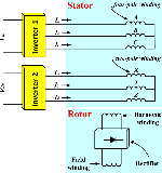
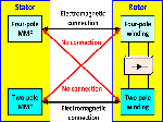
Earlier, a sub-harmonic-based brushless WRSM topology that required dual-inverter configuration was proposed in [8]. The stator winding of this topology was divided into two halves with a distinct star-connection. Each half of the armature winding was supplied with a different magnitude of current. This arrangement achieved the brushless operation for WRSMs; however, the rotor of the machine encountered the high magnitude of unbalanced radial forces which developed due to the different magnitude of currents in the two halves of the machine air-gap. In addition, the efficiency of the machine was also low. Later on, a high-efficient, sub-harmonic-based brushless WRSM topology was proposed in [9]. This topology involved a dual-inverter and circumferentially distributed dual-winding configurations as presented in Fig. 1. The windings of the machine were supplied with different magnitude of currents to develop sub-harmonic magneto-motive force (MMF) in the air-gap of the machine. Besides the brushless operation for WRSMs, this topology offers higher efficiency, higher average torque and lower torque ripple as compared to the sub-harmonic-based brushless WRSM topology proposed in [8]. In addition, the magnitude of the unbalanced radial force for the rotor of the machine was also found to be low.
In this paper, a sub-harmonic-based brushless WRSM topology that involves a single-inverter anddual-winding configurations is proposed. Both stator windings have a different number of turns and are connected in parallel. One of these windings is a four-pole winding, whereas the second winding is a two-pole winding. Unlike the conventional sub-harmonic-based brushless WRSM topologies which require a dual-inverter configuration [8], [9], the proposed topology requires a single inverter which makes it cost-effective, when it is compared to the conventional sub-harmonic-based brushless WRSM topologies. In addition, the proposed topology provides control over the currents of the two-pole winding by employing a variable resistor. Once the inverter supplies the three-phase current to the stator windings, an MMF comprising of two components, a regular fundamental MMF and a sub-harmonic in the air-gap, is produced. The fundamental MMF generates the main stator field whereas the sub-harmonic MMF generates the sub-harmonic field that is used to induce a harmonic current in the two-pole rotor harmonic winding. The induced harmonic current is rectified to inject DC to the rotor field winding and produce a four-pole rotor magnetic field. The magnetic interaction of the four-pole rotor magnetic field with the same number of main stator field poles produces torque. The operation and electromagnetic performance of the proposed topology is discussed in the subsequent sections.
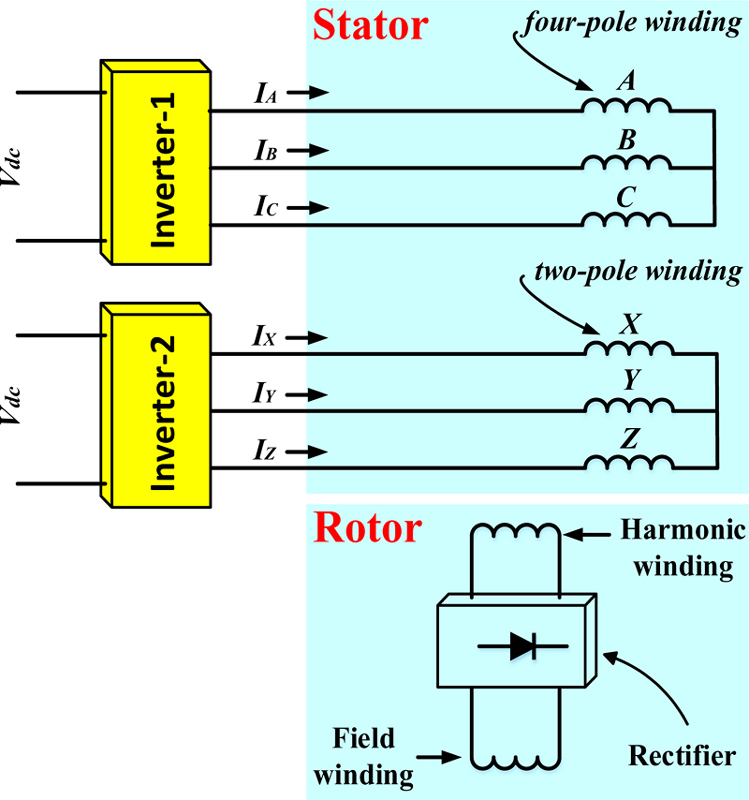
Figure 1: Conventional dual-inverter, sub-harmonic-based BL-WRSM topology.
II. OPERATING PRINCIPLE
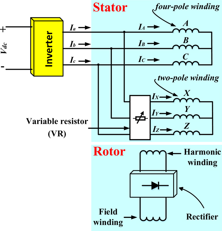
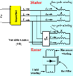
Figure 2: Proposed single-inverter, sub-harmonic-based BL-WRSM topology.
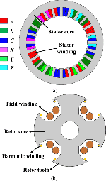
The simplified illustration of the proposed sub-harmonic-based brushless wound rotor synchronous machine (WRSM) topology is presented in Fig. 2. As shown in the figure, this topology consists of two stator windings namely ABC and XYZ. Both windings are connected in parallel through a variable resistor (VR) and are powered from a single inverter. ABC winding is a four-pole winding whereas XYZ winding is a two-pole winding. The purpose of the VR is to control the current of the two-pole winding which eventually adjusts the sub-harmonic MMF component in the air-gap of the machine. This leads to control of the performance of the machine by tuning the resistance of the VR and controlling the sub-harmonic MMF of the machine. The rotor of the topology is equipped with a four-pole rotor field winding and a two-pole harmonic winding. These windings are connected in series through a rectifier. The machine structure which is based on a four-pole and twenty-four-slot configuration is presented in Fig. 3. As the machine is supplied with current (I) from a single inverter, a different magnitude of current flows through ABC and XYZ windings due to their different number of turns. These currents are shown in equations (1) and (2):
| (1) |
| (2) |

Figure 3: (a) Stator and (b) rotor structures of the machine.
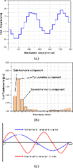
The above currents result in an MMF as shown in Fig. 4 (a). The FFT analysis of the developed MMF results in dominating fundamental and sub-harmonic MMF components as shown in Fig. 4 (b). A simplified illustration of these dominating MMF components is presented in Fig. 4 (c). Mathematically, the MMF of the machine can be calculated using the following equation:
| (3) |
where I is the maximum amplitude of the current, N is the number of ABC winding turns, N is the number of XYZ winding turns, F is the total generated MMF and is the spatial angle.
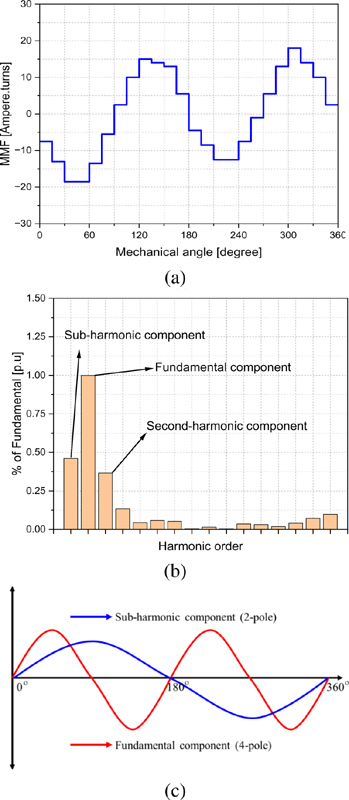
Figure 4: For the proposed single-inverter, sub-harmonic-based BL-WRSM topology: (a) MMF plot, (b) THD of the MMF plot, and (c) MMF components.
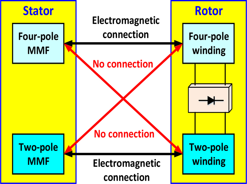
Figure 5: Operating principle of the proposed single-inverter, sub-harmonic-based BL-WRSM topology.
The fundamental MMF component develops the main stator field whereas the sub-harmonic MMF produces the harmonic current in the harmonic winding of the rotor through the electromagnetic induction. This current is rectified and supplied to the rotor field current to develop the four-pole rotor field in order to achieve the brushless operation. The electromagnetic interaction of the four-pole stator and four-pole rotor fields produces torque. The simplified illustration of the operating principle of the proposed sub-harmonic-based brushless WRSM topology is presented in Fig. 5. This figure shows that there is an absence of electromagnetic connection between the four-pole stator MMF and two-pole rotor harmonic winding, and the two-pole stator and four-pole rotor field winding. This is because the speed of both MMF components is not the same. In fact, the speed of the sub-harmonic MMF component is half of the speed of four-pole MMF.
Table 1: Machine parameters
| Parameter | Value |
|---|---|
| Rated power | 4.55 kW |
| Rated speed | 1800 rpm |
| Rated current | 10 A (peak) |
| Stator/rotor outer diameter | 130/79 mm |
| Air-gap length | 0.5 mm |
| Shaft diameter | 20 mm |
| Stack length | 120 mm |
| Stator slots | 24 |
| Field/harmonic winding poles | 4/2 |
| Stator four-pole (ACB) winding turns | 270 |
| Stator two-pole (XYZ) winding turns | 90 |
| Field/harmonic winding turns | 150/15 |
| Variable resistor (VR) | 1 |
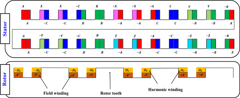
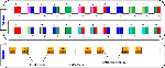
Figure 6: Stator and rotor winding configurations.
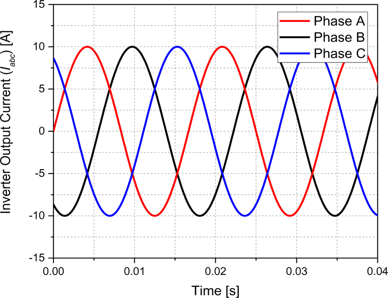
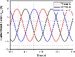
Figure 7: Inverter output current.
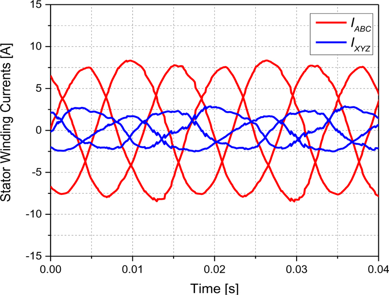
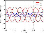
Figure 8: Stator winding currents.
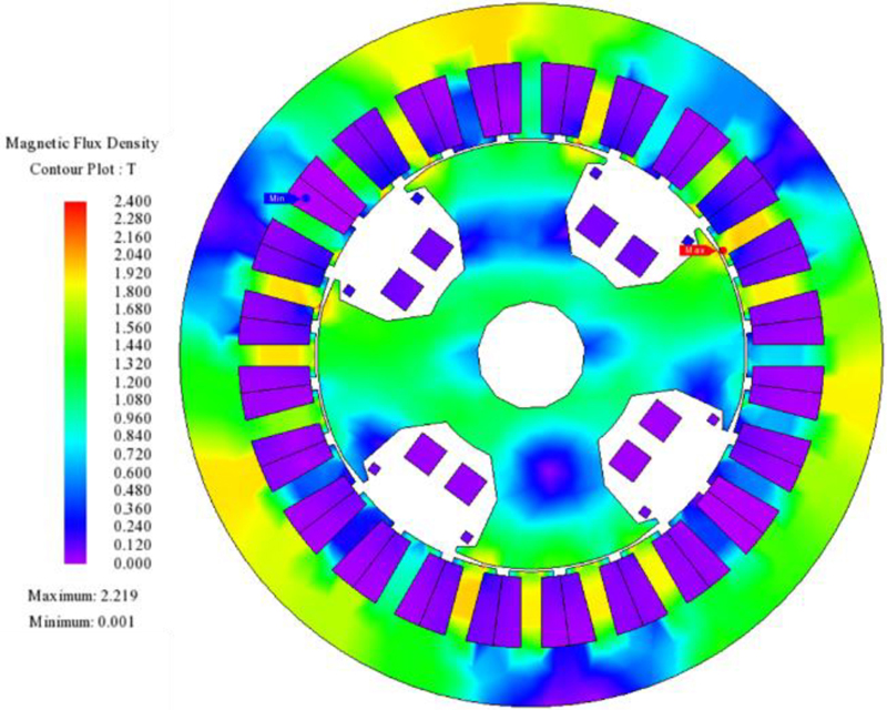
Figure 9: Magnetic flux density plot of the machine.
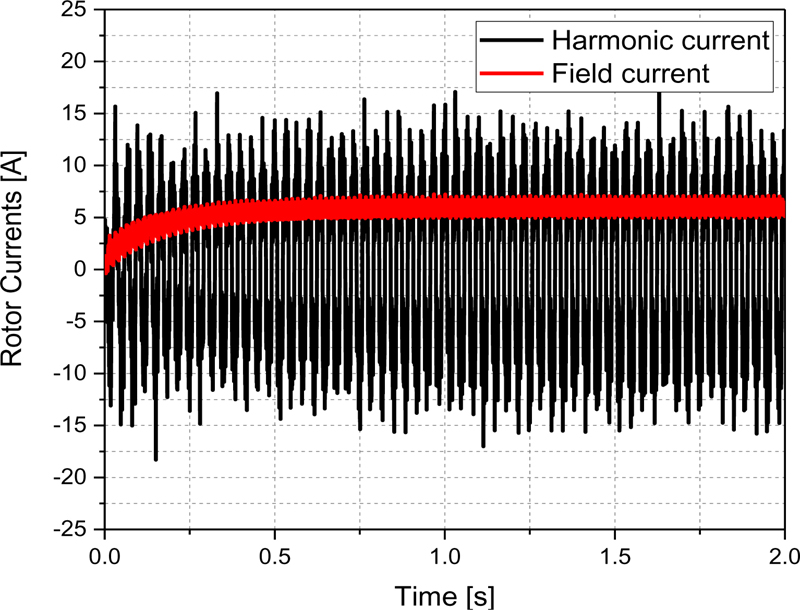
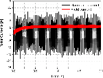
Figure 10: Rotor currents.
III. ELECTROMAGNETIC ANALYSIS
To achieve the electromagnetic performance of the proposed topology, FEA is conducted in JMAG-Designer ver.19.1 for a four-pole, twenty-four-slot machine. The parameters of this machine are presented in Table 1. The stator and rotor structures of the machine are presented in Fig. 3, whereas their winding configurations are presented in Fig. 6. The machine is operated at 1800 rpm and the inverter injects a three-phase current (I) having the magnitude of 10 A (peak) to the two-pole and four-pole stator windings. The inverter output current (I) is presented in Fig. 7. The two-pole winding (XYZ) has 90 turns whereas the four-pole winding (ABC) has 270 turns. As the number of turns for both windings are kept different, a current of unequal magnitude flows through each winding. The currents of ABC and XYZ windings i.e., I, and I are presented in Fig. 8. These currents produce an MMF in the air-gap comprising of fundamental and sub-harmonic components. Figure 9 shows the flux -y plot of the machine. The fundamental component generates the main four-pole stator field whereas the sub-harmonic component induces a harmonic current in the two-pole rotor harmonic winding. The induced harmonic current is rectified to inject DC to the main rotor field winding to create the rotor field. The harmonic and rectified field currents are presented in Fig. 10. The magnetic interaction of the four-pole rotor and stator fields develops torque. This torque is shown inFig. 11.
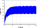
The average generated torque for the proposed sub-harmonic-based brushless WRSM topology is 24.133 Nm under steady-state operation. However, the maximum and minimum torques are around 30.7 Nm and 17.3 Nm, respectively. A torque ripple of around 55.52% is produced which can be minimized by optimizing the machine using parametric optimization algorithms and skewing methods.
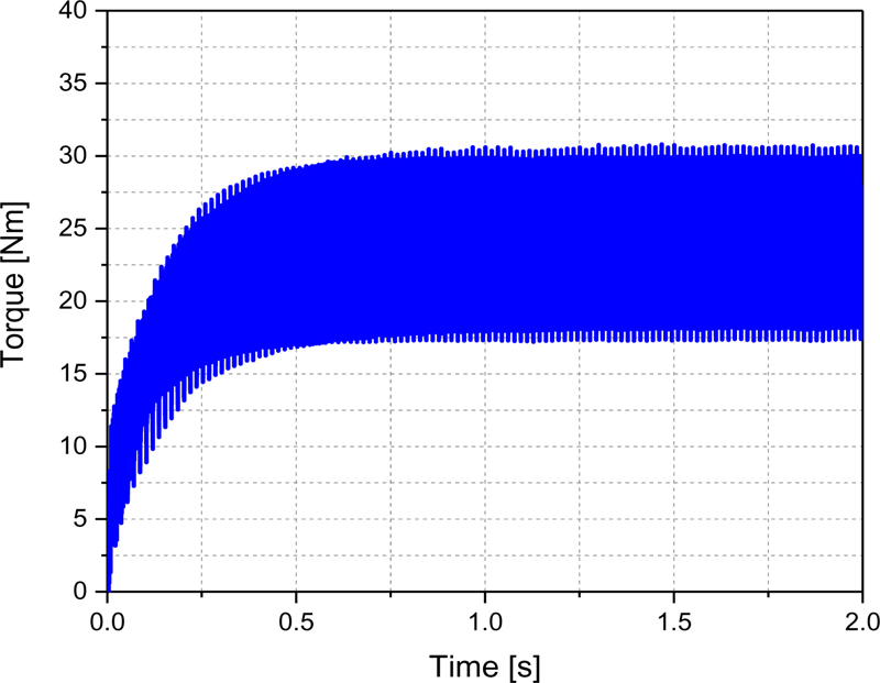
Figure 11: Torque.
IV. CONCLUSION
A sub-harmonic-based, cost-effective, brushless WRSM topology based on a single inverter and dual-stator armature winding configurations was proposed in this paper. The proposed topology used a two-pole and four-pole stator windings having a separate star-connection and a different number of turns. This generated an MMF comprising fundamental and sub-harmonic components. The fundamental component was used to develop the main field and the sub-harmonic component was used to produce a harmonic current in a rotor harmonic winding, which was rectified to excite the rotor field winding to achieve a brushless operation. A four-pole, twenty-four-slot machine was used to achieve electromagnetic torque and justify the operation of the proposed topology.
The proposed brushless WRSM topology is cost-effective, when it is compared to the conventional sub-harmonic-based WRSM topologies which require a dual-inverter configuration. Furthermore, it is simple as it does not require any sophisticated control strategies or power electronics devices, except a typicalthree-phase inverter.
As the two-pole winding is in parallel with the four-pole winding, its current may be controlled using a rheostat to develop the required magnitude of harmonic MMF, which eventually will provide the freedom to develop the required magnitude of output torque.
ACKNOWLEDGMENTS
This work was supported in part by the National Research Foundation of Korea (NRF) grant funded by the Ministry of Science and ICT (No. NRF-2022R1A2C2004874); in part by the Chung-Ang University research grant in 2022; and in part by the Brain Pool (BP) Program through the National Research Foundation (NRF) of Korea funded by the Ministry of Science and ICT (2019H1D3A1A01102988).
REFERENCES
[1] M. Ayub, A. Hussain, G. Jawad, and B. Kwon, “Brushless operation of a wound-field synchronous machine using a novel winding scheme,” IEEE Transactions on Magnetics, vol. 55, no. 6, pp. 1-4, June 2019.
[2] C. Chakraborty, S. Basak, and Y. T. Rao, “Synchronous generator with embedded brushless synchronous exciter,” IEEE Transactions on Energy Conversion, vol. 34, no. 3, pp. 1242-1254, Sep. 2019.
[3] S. S. H. Bukhari, A. A. Memon, S. Madanzadeh, G. J. Sirewal, J. Doval-Gandoy, and J.-S. Ro, “Novel single inverter-controlled brushless wound field synchronous machine topology,” Mathematics, vol. 9, no. 15, pp. 1739, 2021.
[4] S. S. H. Bukhari, F. H. Mangi, I. Sami, Q. Ali, and J.-S. Ro, “High-harmonic injection-based brushless wound field synchronous machine topology,” Mathematics, vol. 9, no. 15, pp. 1721, 2021.
[5] G. Jawad, Q. Ali, T. A. Lipo, and B. I. Kwon, “Novel brushless wound rotor synchronous machine with zero-sequence third-harmonic field excitation,” IEEE Transactions on Magnetics, vol. 52, no. 7, pp. 1-4, July 2016.
[6] N. Jiao, W. Liu, Z. Zhang, T. Meng, J. Peng, and Y. Jiang, “Field current estimation for wound-rotor synchronous starter-generator with asynchronous brushless exciters,” IEEE Transactions on Energy Conversion, vol. 32, no. 4, pp. 1554-1561, 2017.
[7] F. Yao, D. Sun, L. Sun, and T. A. Lipo, “Dual third-harmonic-current excitation principle of a brushless synchronous machine based on double three-phase armature windings,” 2019 22nd International Conference on Electrical Machines and Systems (ICEMS), Harbin, China, pp. 1-4, 2019.
[8] Q. Ali, T. A. Lipo, and B. I. Kwon, “Design and analysis of a novel brushless wound rotor synchronous machine,” IEEE Transactions on Magnetics, vol. 51, no. 11, pp. 1-4, Nov. 2015.
[9] S. S. H. Bukhari, Q. Ali, J. Doval-Gandoy, and J.-S. Ro, “High-efficient brushless wound rotor synchronous machine topology based on sub-harmonic field-excitation technique,” Energies, vol. 14, no. 15, pp. 4427, 2021.
BIOGRAPHIES

Syed Sabir Hussain Bukhari received his B.E degree in Electrical Engineering from Mehran University of Engineering and Technology, Jamshoro, Pakistan, in 2009, and Ph.D. from the Department of Electronic Systems Engineering, Hanyang University, South Korea in 2017. He joined Sukkur IBA University as an Assistant Professor in December 2016. He is currently working as a Research Professor at Chung-Ang University, Seoul, South Korea under the Korean Research Fellowship (KRF) program. His main research interests include electric machine design, power quality and drive controls.

Jong-Suk Rob received his B.S. degree in Mechanical Engineering from Han-Yang University, Seoul, Korea, in 2001 and his Ph.D. in Electrical Engineering from Seoul National University (SNU), Seoul, Korea, in 2008.
He conducted research at the R&D center of Samsung Electronics as a Senior Engineer from 2008 to 2012. From 2012 to 2013, he was at Brain Korea 21 Information Technology of SNU, as a Post-Doctoral Fellow. He conducted research at the Electrical Energy Conversion System Research Division of the Korea Electrical Engineering & Science Research Institute as a Researcher in 2013. From 2013 to 2016, he worked at Brain Korea 21 Plus, SNU, as a BK Assistant Professor. In 2014, he was at the University of Bath, UK. Currently, he is an Associate Professor of the School of Electrical and Electronics Engineering, Chung-Ang University, Seoul, Korea.
His research interests include the analysis and optimal design of next-generation electrical machines using smart materials such as electromagnetic, piezoelectric, and magnetic shape memory alloys.
ACES JOURNAL, Vol. 38, No. 5, 371–376
doi: 10.13052/2023.ACES.J.380510
© 2023 River Publishers