Mainlobe Interference Suppression via Eigen-Projection Processing and Covariance Matrix Reconstruction in Array Antenna
Bin Yang1, Wenxing Li1, and Si Li2
1College of Information and Communication Engineering, Harbin Engineering University, Harbin,
Heilongjiang 150001, China
2School of Electronics and Information, Jiangsu University of Science and Technology, Zhenjiang,
Jiangsu 212003, China
yb_alonline@126.com, liwenxing@hrbeu.edu.cn, lisi0511@just.edu.cn
Submitted On: November 3, 2020; Accepted On: October 21, 2021
Abstract
When the received data contains the desired signal, the performance of most mainlobe interference suppression methods is seriously degraded. To solve this problem, a novel mainlobe interference suppression method based on eigen-projection processing and covariance matrix reconstruction for array antenna is proposed in this paper. The method constructs the sidelobe interference plus noise covariance matrix (SINCM) and remove the mainlobe data of the covariance matrix. Then, it uses eigen-projection technology to remove the mainlobe interference in the received data and correct the SINCM to make the proposed method has better ability to suppress the mainlobe interference and sidelobe interference when the received data contains the desired signal. Simulation results demonstrate the superior performance of the proposed beamformer relative to other existing methods.
Index Terms: array antenna, eigen-projection, mainlobe interference, reconstruction.
I. INTRODUCTION
The purpose of robust adaptive beamforming technology is to suppress other signals except the desired signal under the irrational environment, so as to improve the output performance of the beamformer. As a basic implementation to achieve spatial filtering, adaptive beamforming has been applied to several areas, such as array antenna, radar, sonar, remote sensing, seismology, wireless communication, etc. [1, 2]. Usually, traditional adaptive beamformer mainly focused on the suppression of sidelobe interference [3]. However, for array antenna, interference would distort the mainlobe thus significantly decrease performance once it fell into the mainlobe area. To solve this problem, many approaches of mainlobe interference suppression have been proposed [4, 5, 6, 7, 8, 9, 10, 11, 12, 13, 14, 15, 16].
The block matrix preprocessing (BMP) method is developed in [4], which works well when the direction of mainlobe interference is known. However, it also gives rise to the reduction of the degrees of freedom. For the problem of mainlobe direction shifting caused by the mainlobe interference suppression based on blocking matrix preprocess, a modified BMP method is proposed in [5]. But its performance improvement is limited. The eigen-projection matrix preprocessing (EMP) method is proposed in [6], which suppresses the mainlobe interference by eigen-projection method. However, this method is prone to mainlobe offset and sidelobe rise. To solve this problem, various modified EMP methods are proposed in [7, 8, 9]. In order to suppress multiple mainlobe interferences, a new method based on EMP method and similarity constraints is proposed in [10]. The above methods can suppress the mainlobe interference effectively only when there is no desired signal in the received data, otherwise they are invalid. But in fact, it is difficult for us to get such data. In order to overcome this problem, a robust mainlobe interference suppression method is proposed in [11], which achieves high accuracy of the direction of arrival and power estimation of source. However, its computational complexity is very high. To further improve the array antenna performance, modified EMP methods are proposed in [12, 13]. Both methods reconstruct the sidelobe interference plus noise covariance matrix (SINCM) and calculate the eigen-projection matrix to remove the mainlobe interference in the received data of array antenna. However, once the received data was processed via eigen-projection, the original sampling covariance matrix would change. Hence, the weight vector obtained from SINCM cannot suppress the sidelobe interference of the processed data. Sidelobe null shifts, which reduce the ability of array antenna to suppress sidelobe interference, and the output performance is far from the optimal value. A mainlobe interference suppression method for bistatic airborne radar is proposed in [14], the core idea of this method is based on BMP method to remove the mainlobe interference. This means that this method wastes a degree of freedom. In [15, 16], the methods for distributed array to suppress mainlobe interference are proposed. In order to facilitate the construction of the signal model, this paper only considers the uniform linear array (ULA) as the research object.
In this paper, a novel mainlobe interference suppression method based on eigen-projection processing and covariance matrix reconstruction for array antenna is proposed. The proposed method first calculates the eigen-projection matrix through the reconstructed mainlobe interference plus noise covariance matrix (MINCM). Then, the SINCM is reconstructed and processed using the eigen-projection matrix to form null at the direction of sidelobe interference accurately. Finally, we obtain the weight vector. Simulation results show that the proposed method has higher output signal-to-interference-plus-noise ratio (SINR) when the desired signal is contained in the received data.
The advantages of the proposed method are as follows:
1. The output SINR of the proposed method is higher when the array antenna suffers from the mainlobe interference.
2. The array antenna has better ability to suppress mainlobe interference and sidelobe interference when the received data contains desired signal.
The rest of this paper is summarized below. The signal model is described in Section II. Section III describes the proposed method. Simulation results are described in Section IV. In Section V, we make a conclusion.
II. SIGNAL MODEL OF ARRAY ANTENNA
Consider a ULA, which is composed of N omnidirectional antennas spaced by half a wavelength, receiving uncorrelated far-field narrowband signals. The sample data of array antenna at the k snapshot is modeled as:
| (1) |
where , and denote the desired signal, interference and noise, respectively. and represent the number of mainlobe interferences and sidelobe interferences, respectively. Moreover, these components are mutually independent. is the additive spatially Gaussian white noise with zero mean and variance . and denote the steering vector of the desired signal and the interferences, respectively. For the signal with the direction of , the steering vector of the signal can be expressed as:
| (2) |
where (•) is the transpose product, is the wavelength of the signal, and is the distance between two adjacent antennas of the ULA. The output of the array antenna is given as:
| (3) |
where is the weight vector of the array antenna. The minimum variance distortionless response (MVDR) beamformer is obtained by minimizing the variance of the interference and noise at the output while constraining the target response to be unity. It can be formulated as:
| (4) |
where is the desired signal steering vector, is the interference plus noise covariance matrix (INCM) matrix. In practice, is unavailable, so replace it with the following sample covariance matrix (SCM):
| (5) |
where K is the number of snapshots. Therefore, by solving the above problems, the weighted vector of the beamformer can be obtained as:
| (6) |
It is the sample matrix inversion (SMI) beamformer.
III. THE PROPOSED METHOD
In this section, a mainlobe interference suppression method via eigen-projection processing and covariance matrix reconstruction for array antenna is proposed.
A. The construction of eigen-projection matrix
For a ULA, the mainlobe width can be expressed as:
| (7) |
where is the direction of the desired signal. Therefore, the mainlobe angle area of the array antenna can be expressed as:
| (8) |
It is assumed that the desired signal angle area is:
| (9) |
There is no mainlobe interference in . The incident angle area of mainlobe interference is as follow:
| (10) |
Process the SCM with eigen-decomposition.
| (11) |
where is signal subspace, is the matrix of corresponding larger eigenvalues, is the noise subspace, and is the corresponding eigenvalue matrix.
In the above angle area , the MINCM of the mainlobe interference region is then reconstructed by using MUSIC spatial spectrum estimation, such that:
| (12) |
By eigen-decomposing the matrix, can then be expressed as:
| (13) |
where is the eigenvalue in order of value, , is the corresponding eigenvector. Meanwhile, the mainlobe interference subspace can be expressed as:
| (14) |
The eigen-projection matrix which can suppress the mainlobe interference can be formulated as:
| (15) |
B. The reconstruction of SINCM
According to eqn. (8), the sidelobe angle area can be expressed as:
| (16) |
In this angle area, the simple spatial spectrum estimation method is used to determine the approximate angle regions of sidelobe interference . The Capon spatial spectrum method [17] is used to determine the power at each position of the spatial spectrum:
| (17) |
The INCM in each sidelobe interference angle area is expressed as following:
| (18) |
Then the SINCM of the whole sidelobe region can be expressed as follows:
| (19) |
According to eqn. (15), process the receiving data using the eigen-projection matrix. The processed data can be expressed as:
| (20) |
When desired signal of array antenna is contained in the received signal, the MVDR beamforming algorithm will be easily disturbed by the desired signal direction error, resulting a poor output performance. Assume that there is no desired signal in the received signal, eqn. (20) became:
| (21) |
The corresponding covariance matrix can be formulated as:
| (22) |
where is the power of i sidelobe interference, is the power of noise. is the sidelobe interference covariance matrix. Then, the reconstructed SINCM can be expressed as:
| (23) |
In the proposed method, the power of noise can be expressed as:
| (24) |
According to eqn. (19), (23), and (24), the SINCM can be reconstructed as:
| (25) |
C. Calculate the weight vector of array antenna
Based on the previous discussion, replace the SCM in eqn. (6) with in eqn. (25), then the adaptive weight vector of array antenna can be expressed as:
| (26) |
Therefore, the output data of array antenna can be expressed as:
| (27) |
D. Summary of proposed method
The proposed algorithm can be implemented by several steps and summarized as follows:
1. Construct the covariance matrix as eqn. (12);
2. Eigen-decompose as eqn. (13) and construct the eigen-projection matrix as eqn. (15);
3. Reconstruct the SINCM with eqn. (19) and (25);
4. Calculate the adaptive weight vector of array antenna by eqn. (26).
IV. SIMULATIONS AND COMPARISONS
Consider a ULA with 16 antennas spaced half-wavelength. The desired signal direction is with signal-to-noise ratio (SNR) . Two sidelobe interferences impinge on the ULA from and with interference-to-noise ratio (INR) and respectively. A mainlobe interference impinge from with INR . The snapshots of received data is 100. The signal and interference are statistically independent, and the added noise is Gaussian white noise. All experimental results are from 100 independent Monte Carlo experiments. The proposed method in this paper is compared to SMI, EMP-CMR [7], EMP-SC [10], MIS-CIE [11], EMP-CMIR [12], and EMP-CMSR [13]. For the case of EMP-CMR and EMP-CMIR methods, there is no desired signal in the received data.
A. Adaptive beampatterns of array antenna
In Figure 1, the beam patterns of every method are compared. It is obvious that the beampattern of SMI method is affected, while other methods can form nulls at the direction of interference effectively.
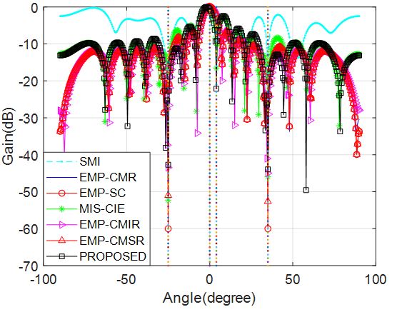
Fig. 1. Adaptive beampatterns of array antenna comparison.
B. Output data comparison of array antenna
Figure 2 compares the output data of every method with desired signal. It is observed from Figure 2 that the output data of EMP-CMR, EMP-SC, MIS-CIE, and the proposed method are more similar to the desired signal. Table 1 shows the correlation coefficient between the output data of every method and the real desired signal. It is obvious that the correlation coefficient of the proposed method is the highest.
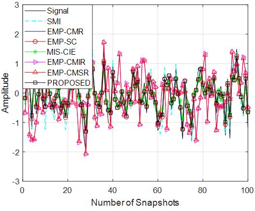
Fig. 2. Output data comparison of array antenna comparison.
Table 1: Correlation coefficient comparison
| Methods | Correlation Coefficient |
| SMI | 0.8833 |
| EMP-CMR | 0.9584 |
| EMP-SC | 0.9584 |
| MIS-CIE | 0.9328 |
| EMP-CMIR | 0.3606 |
| EMP-CMSR | 0.3799 |
| PROPOSED | 0.9589 |
C. Output SINR versus the input SNR
In this section, we compare the output SINR of every method when the input SNR varies from to .
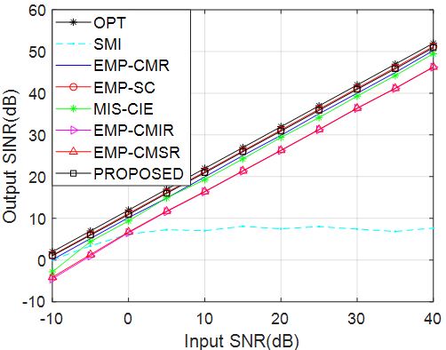
Fig. 3. Output SINR versus the input SNR.
In Figure 3, the output SINR versus the input SNR are compared. From this figure, it is observed that the output SINR of the proposed method and EMP-SC are very close and perform better than other methods. It is worth noting that the desired signal was not contained for the cases of EMP-CMR and EMP-SC methods.
D. Output SINR versus the number of snapshots
In this section, we compare the output SINR of every method when the number of snapshots varies from 10 to 100. Figure 4 displays the output SINR versus the number of snapshots. It is clearly shown that the output SINR of the proposed method is closer to the optimal value after the number of snapshots is 20. This shows that the convergence speed of this method is very fast.
E. Output SINR versus INR of mainlobe interference
In this section, we compare the output SINR of every method when the INR of the mainlobe interference varies from to . Figure 5 shows the variation curve of the output SINR versus INR of the mainlobe interference. Compared with other methods, the output SINR of the proposed method and EMP-SC are similar and higher than other methods obviously. It should be noticed that for this case, when the proposed method is employed, the received data contains the desired signal.
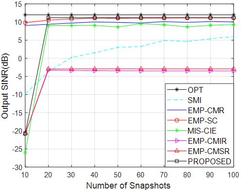
Fig. 4. Output SINR versus the number of snapshots.
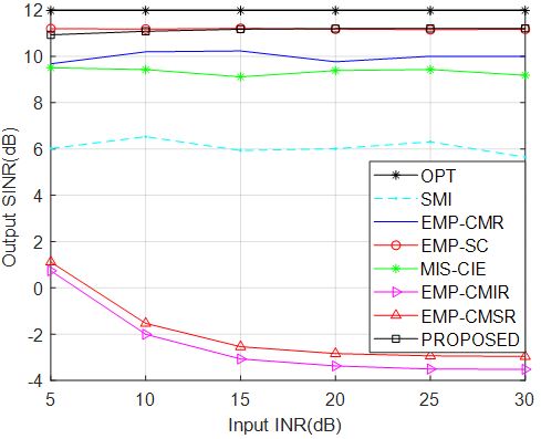
Fig. 5. Output SINR versus INR of the mainlobe interference.
F. Output SINR versus the direction of mainlobe interference
In this section, we compare the output SINR of every method when the mainlobe interference direction varies from to .
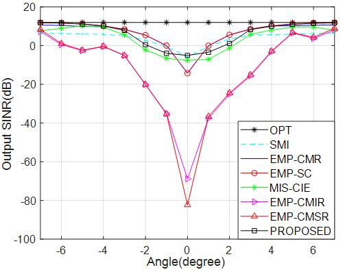
Fig. 6. Output SINR versus the direction of mainlobe interference.
Figure 6 compares the output SINR of every method versus the direction of mainlobe interference. In this figure, it is obvious that the output SINR of the proposed method is higher and closer to the optimal value.
V. CONCLUSION
This paper proposed a novel mainlobe interference suppression method for array antenna beamforming based on eigen-projection processing and covariance matrix reconstruction specified for the problem when desired signal is contained in the received data, which can not only suppress the mainlobe interference impinge but also the sidelobe interference effectively. Compared with other existing methods, simulation results demonstrated that the proposed method can achieve better performance when the mainlobe interference and sidelobe interference are co-existent and the desired signal exists in the received data of array antenna.
ACKNOWLEDGMENT
This paper is supported by the Natural Science Foundation of Jiangsu province of China (BK20190956).
REFERENCES
[1] S. Mohammadzadeh and O. Kukrer, “Robust adaptive beamforming with improved interferences suppression and a new steering vector estimation based on spatial power spectrum,” Circuits Syst Signal Process, vol. 38, pp. 4162-4179, 2019.
[2] A. Hassanien, M. G. Amin, Y. D. Zhang, and F. Ahmad, “Dual-function radar-communications: Information embedding using sidelobe control and waveform diversity,” IEEE Transactions on Signal Processing, vol. 64, no. 8, pp. 2168-2181, 2016.
[3] Y. Gu and A. Leshem, “Robust adaptive beamforming based on interference covariance matrix reconstruction and steering vector estimation,” IEEE Transactions on Signal Processing, vol. 60, no. 7, pp. 3881-3885, 2012.
[4] R. Li, Y. Wang, and S. Wan, “Robust adaptive beam forming under main lobe interference conditions,” System Engineering and Electronics, vol. 24, no. 7, pp. 4-7, 2002.
[5] J. Yang and C. Liu, “Improved mainlobe interference suppression based on blocking matrix preprocess,” Journal of Electrical and Computer Engineering, 2015, pp. 1-8, 2015.
[6] R. Li, Y. Wang, and S. Wan, “Research of reshaping adapted pattern under mainlobe interference conditions,” Modern Radar, vol. 24, pp. 50-55, 2002.
[7] X. Yang, Z. Zhang, T. Zeng, L. Teng, and T. K. Sarkar, “Mainlobe interference suppression based on eigen-projection processing and covariance matrix reconstruction,” IEEE Antennas & Wireless Propagation Letters, vol. 13, pp. 1369-1372, 2014.
[8] L. Lu and Y. Liao, “Improved algorithm of mainlobe interference suppression based on eigen-subspace,” 2016 International Conference on Communication and Signal Processing (ICCSP), pp. 0133-0137, 2016.
[9] J. Qian, Z. He, F. Jia, and X. Zhang, “Mainlobe interference suppression in adaptive array,” 2016 IEEE 13th International Conference on Signal Processing (ICSP), pp. 470-474, 2016.
[10] J. Qian and Z. He, “Mainlobe interference suppression with eigenprojection algorithm and similarity constraints,” Electronics Letters, vol. 52, no. 3, pp. 228-230, 2016.
[11] Y. Wang, Q. Bao, and Z. Chen, “Robust mainlobe interference suppression for coherent interference environment,” EURASIP Journal on Advances in Signal Processing, vol. 135, no. 1, pp. 1-7, 2016.
[12] Z. Luo, H. Wang, W. Lv, and H. Tan, “Mainlobe anti-jamming via eigen-projection processing and covariance matrix reconstruction,” ICE Transactions on Fundamentals of Electronics Communications and Computer ences, vol. E100.A, no. 4, pp. 1055-1059, 2017.
[13] L. Xin, Y. Baoguo, and H. Ping, “Mainlobe interference suppression via eigen-projection processing and covariance matrix sparse reconstruction,” ICE Electronics Express, vol. 15, no. 17, pp. 20180683-20180683, 2018.
[14] D. Xia, L. Zhang, T. Wu, and X. Meng, “A mainlobe interference suppression algorithm based on bistatic airborne radar cooperation,” 2019 IEEE Radar Conference (RadarConf), pp. 1-6, 2019.
[15] J. Chen, X. Chen, H. Zhang, K. Zhang, and Q. Liu, “Suppression method for main-lobe interrupted sampling repeater jamming in distributed radar,” IEEE Access, vol. 8, pp. 139255-139265, 2020.
[16] Q. Sun, Q. Zhang, X. Huang, and Q. Gao, “Target detection and localization method for distributed monopulse arrays in the presence of mainlobe jamming,” Journal on Advances in Signal Processing, vol. 1, 2020.
[17] Y. Gu, N. A. Goodman, S. Hong, et al., “Robust adaptive beamforming based on interference covariance matrix sparse reconstruction,” Signal Processing, vol. 96, pp. 375-381, Mar. 2014.
ACES JOURNAL, Vol. 36, No. 11, 1468–1473.
doi: 10.13052/2021.ACES.J.361111
© 2021 River Publishers