A Compact and High-Performance Shielding Enclosure by Using Metamaterial Design
Keyi Cui, Dan Shi, Chi Sun, and Xiaoyong Liu
Department of Electronic Engineering, Beijing University of Posts and Telecommunications, Beijing 100876, China
cuikeyi@buptemc.com, shidan@buptemc.com, sunchi@buptemc.com, liuxiaoyong@srtc.org.cn
Submitted On: June 29, 2021; Accepted On: October 18, 2021
Abstract
A compact and high-performance shielding enclosure designed by metamaterial structure based on frequency selective surface (FSS) is proposed. The enclosure has large holes for convenience of airflow and cable access. However, it can achieve great shielding performance by maintaining more than 40 dB attenuation. The shield is composed of n n unit cells, and each unit cell is designed by knitting the 2.5-dimensional loop-type elements interconnected through vias. This design shows promising capability of size reduction, bandwidth expansion, and shielding effectiveness enhancement. Moreover, the enlarged holes on the FSS are helpful for the ventilation and heat dissipation. The size of the proposed 2.5-D FSS is only 0.0970.097, where corresponds to free space wavelength of resonance frequency. The proposed structure provides 3.38 GHz (3.21–6.59 GHz) wide shielding bandwidth. Furthermore, it has stable response to the wide-angle incident wave ranging from 0 to 85 with more than 40 dB attenuation at 4.83 GHz for both x-polarization and y-polarization. The proposed FSS is practically useful for the shielding of fifth generation (5G) wireless systems, WiMAX, and WLAN.
Index Terms: Electromagnetic shielding, fifth generation (5G) wireless systems, frequency selective surfaces (FSSs), metamaterial, ventilation.
I. INTRODUCTION
A metallic enclosure is often used as a shield to protect sensitive and critical electronic devices from electromagnetic interference. It is indispensable as a part of electronic products to block against unwanted electromagnetic signals [1, 2, 3]. The high-frequency signals in the fifth generation (5G) communication bring a challenge to the shielding design of electronic products. The wireless signals will be coupled into the interior through the holes on the metallic enclosure and cause electromagnetic interference [4]. In some cases, metallic shields are huge and heavy, which are inapplicable for compact and lightweight electronic products [5, 6, 7].
The influence of holes on shielding effectiveness (SE) of a shield has been widely investigated [8, 9, 10]. The literature shows that the size of hole significantly affects the SE. The ventilation may degrade severely due to blockage of deposit dust in smaller holes. The relationship among SE, the diameter of holes, and the frequency (wavelength) is given as follows [11]:
| (1) |
where SE represents shielding effectiveness, denotes free space wavelength, and d is hole diameter. When the SE remains unchanged, the smaller hole diameter is required for higher frequency. For example, if the SE is required to be more than 26 dB for 5G signal, the hole diameter should be smaller than 1.5 mm. However, the small hole is more likely to deposit dust due to blockage, which may threaten the security of electronic equipment. Therefore, well-performed shielding designs with holes are in demand, and frequency selective surface (FSS) is an optimal choice.
FSS is a periodic structural array printed on a dielectric substrate. In some frequency bands, FSS can act as a band-stop or band-pass filter [12, 13, 14]. The frequency selective behavior of FSS depends on the geometry of cells and resonance frequency. Recently, FSS for shielding has been proposed. In [5], a reconfigurable metamaterial for electromagnetic interference shielding is proposed, and PIN diodes are used to interconnect components to control the specific polarization properties. In [15], a compact dual band-stop FSS is proposed. It consists of a modified double square loop with folded strips into the inner space at the four corners of square loops to control resonant wavelengths. In [16], knitting the loop-type FSS elements in 2.5-D is proposed, where segments of the loop are placed alternately on the top and bottom surfaces of the substrate and then interconnected through metallic vias. In [17], a dual-frequency miniaturized FSS with a closely spaced band of operation is proposed, and its SE is less than 20 dB. In [18], the new miniaturized FSS is based on interconnecting the convoluted segments, which are arranged alternately on both sides of the substrate. The SE does not exceed 30 dB. In [19], a compact FSS based on the 2.5-D Jerusalem cross is designed whose SE is less than 40 dB. A compact FSS composed of a swastika unit cell with the smallest dimension of 7 mm 7 mm is described in [20]. The SE is less than 35 dB. Very closely located dual-band FSSs are discussed in [21]. And the SE is less than 20 dB. A novel dual-band FSS designed by [22] with closely spaced frequency response is proposed. The SE is less than 35 dB. A convoluted and connection FSS unit cell is reported in [23] for shielding 5G electromagnetic signals. The SE is less than 40 dB. In the above literature, the maximum angular stability does not exceed 75, and the heat dissipation is poor due to the seamless structure. Although so many FSSs for electromagnetic interference shielding have been proposed, high SE, stable incidence angle, and sufficient heat dissipation are still tricky problems. Therefore, a miniaturized FSS with high shielding performance and vent holes is in demand.
In [4], an FSS with holes is proposed. Although the SE is more than 40 dB, the unit cell size (0.46 0.46, where corresponds to free space wavelength of resonance frequency) is too large for miniaturized electronic devices. Therefore, a novel compact FSS for shielding 5G signals is proposed in this paper. The FSS unit cell has a large square aperture with 3.2 mm length. However, the SE is more than 40 dB and the heat dissipation is better than metallic enclosure and other FSSs in published literature. In addition, the unit cell of the proposed FSS has a compact size of 0.097 0.097 through knitting the square loop in 2.5-D. The resonance frequency of the proposed FSS is stable as the incidence angle increases from 0 to 85.
The paper is organized as follows. The details of the FSS geometry design and performance are described in Section II. The parameter analysis and equivalent circuit model is introduced in Section III. Section IV provides the conclusion.
II. FSS DESIGN AND PERFORMANCE
The structure of the unit cell of the proposed FSS is shown in Figure 1.
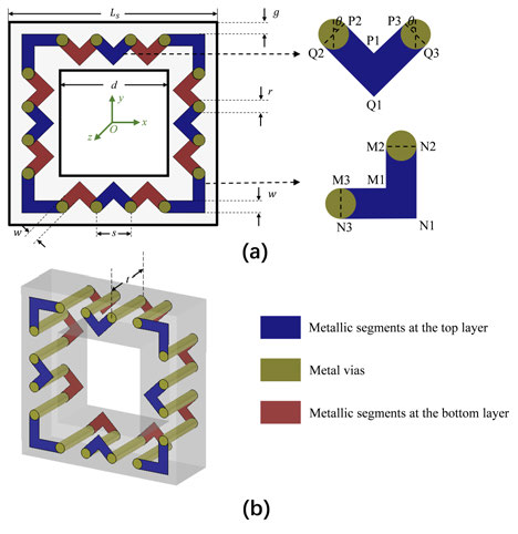
Fig. 1. Structure of the unit cell of the proposed FSS. (a) Top view. (b) Perspective view.
Compared with plane FSS, the proposed 2.5-D FSS is improved by square-loop unit consisting mainly of three parts. The first part is metal vias, which connect metallic split rings across two sides of substrate. Vias are an important part of FSS for miniaturization, which elongate total loop perimeter and increase equivalent inductance and capacitance [16]. The second part is the metallic segments at the top and bottom layers. The resonance frequency can be adjusted by extending the loop perimeter through inward convolution. The square loop is selected because of its excellent performance in the stability for various incidence angles, cross-polarization, bandwidth, and band separation [24]. The third part is the substrate, which is FR-4 lossy layer with relative permittivity of 4.3 and loss tangent of 0.025. The effective dielectric constant is calculated as follows [25]:
| (2) |
The resonance frequency will decrease as the dielectric permittivity increases. Therefore, it is very important to consider the dielectric properties of the substrate in FSS design. In addition, the thickness of the substrate can also significantly affect the shielding performance, which will be analyzed in Section III.
Table 1: Parameters of the unit cell
| No. | Parameters | Value |
| 1 | L | 6 mm |
| 2 | g | 0.32 mm |
| 3 | w | 0.36 mm |
| 4 | r | 0.36 mm |
| 5 | s | 1 mm |
| 6 | d | 3.2 mm |
| 7 | t | 2 mm |
| 8 | 45 |
For sufficient heat dissipation and wiring, the diameter (d) of the hole is set to 3.2 mm and the thickness (t) is 2 mm. Finally, the proposed FSS is designed to provide more than 40 dB shielding attenuation at the center frequency of 4.83 GHz. The width of the loop, the gap (g) between adjacent loops, the side length () of the whole unit, and the radius (r) of vias of loops are given in Table 1. The design details of one of the triangular strips and right-angled strips are given in Table 2 and other strips can be obtained by means of rotation or translation.
Table 2: Design details of triangular and right-angled strips
| Point Name | Coordinate |
| P1 | (0, 2.25456, 0) |
| P2 | (–0.372721, 2.62728, 0) |
| P3 | (0.372721, 2.62728, 0) |
| Q1 | (0, 1.7455, 0) |
| Q2 | (–0.627279, 2.37272, 0) |
| Q3 | (0.627279, 2.37272, 0) |
| M1 | (2.32, –2.32, 0) |
| M2 | (2.32, –1.5, 0) |
| M3 | (1.5, –2.32, 0) |
| N1 | (2.68, –2.68, 0) |
| N2 | (2.68, –1.5, 0) |
| N3 | (1.5, –2.68, 0) |
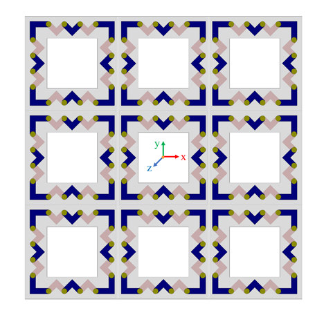
Fig. 2. Array of the proposed FSS.
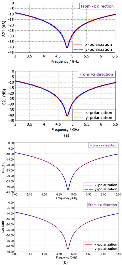
Fig. 3. Transmission coefficients at normal incidence from –z and +z directions for x-polarization and y-polarization simulated by (a) CST and (b) HFSS.
The array of the proposed FSS is shown in Figure 2. The entire model is simulated in CST Microwave Studio based on finite integral technique (FIT) method and ANSYS HFSS based on finite element method (FEM), respectively. FIT method describes Maxwell’s equations on a grid space with no restriction on grid type, which is widely applied in solving electromagnetic field problems in both time and frequency domains. By discretizing a large system into finite elements, FEM method converts some complex boundary value problems to a system of simple equations, which is also a common numerical method in the electromagnetic field. In two simulation softwares, the periodic boundary conditions are set in the x-axis and y-axis to represent the infinite periodic FSS array and the proposed FSS is excited by Floquet ports in the z-axis. Besides, the open (add space) boundaries are required to be set in the z-axis in CST simulation.
Here, the transmission coefficient is chosen to evaluate the shielding performance of the proposed FSS and smaller transmission coefficient represents better shielding performance. The transmission coefficients at normal incidence of the proposed FSS simulated by CST and HFSS are shown in Figure 3. The results of two electromagnetic simulators are basically consistent, which further verifies the validity of the proposed FSS. Simulation results show that the proposed FSS provides more than 40.74 dB attenuation for a bandwidth of 3.38 GHz (3.21–6.59 GHz) at the center frequency of 4.83 GHz and can fully meet the shielding requirement. It can be seen that the results with excitation from both +z and –z directions are the same. In addition, the proposed FSS behaves identically for both x-polarization and y-polarization, which provides stability in shielding.
The angular stability is also investigated. The S21 at different incidence angles from –z and +z directions for x-polarization and y-polarization is shown in Figures 4 and 5. Simulation results show that the S21 with excitation from both +z and –z directions is the same. It can also be seen that the resonance frequency of the proposed FSS deviates less than 0.5% at various incident angles. Therefore, for x-polarization and y-polarization, the proposed FSS can provide a stable S21 up to 85 incident angle at the frequency of 4.83 GHz. As shown in Figures 4 and 5, the S21 for x-polarization decreases when the incidence angle increases. However, the S21 for y-polarization increases when the incidence angle increases. The phenomenon is mainly attributed to wave impedance change, which validates the basic theory of FSS mentioned in [25].
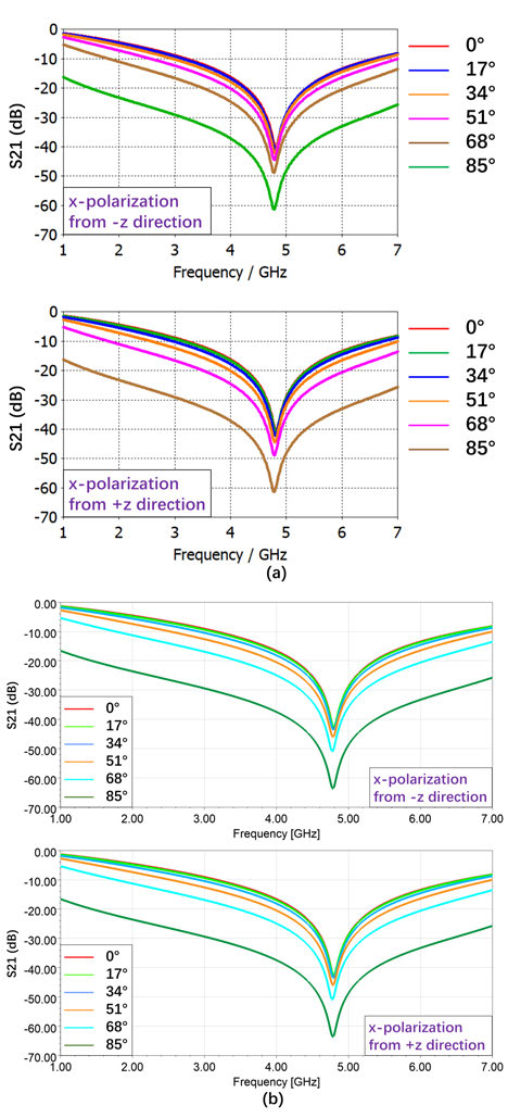
Fig. 4. Transmission coefficients at different incident angles from –z and +z directions for x-polarization simulated by (a) CST and (b) HFSS.
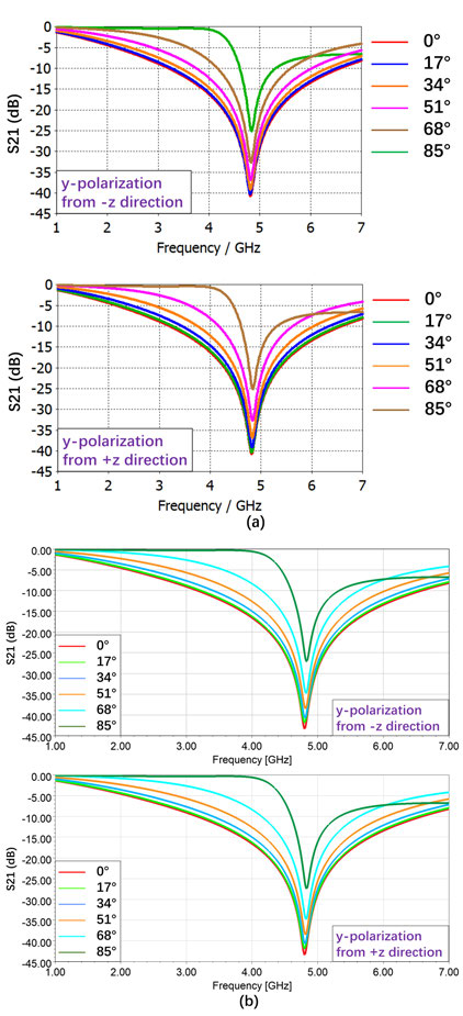
Fig. 5. Transmission coefficients at different incident angles from –z and +z directions for y-polarization simulated by (a) CST and (b) HFSS.
III. PARAMETER ANALYSIS
The distribution of surface current at the resonance frequency of 4.83 GHz is illustrated in Figure 6.
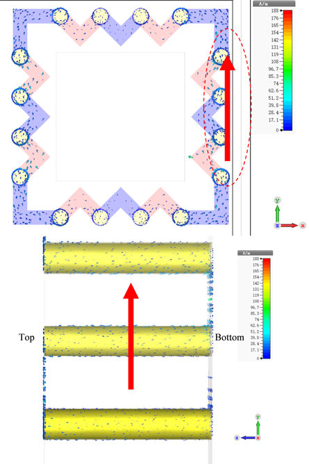
Fig. 6. Distribution of the surface current.
The substrate thickness t is much less than free space wavelength of resonance frequency. The surface current flows through the metal vias, which provide additional inductance due to elongation of the loop conductor. Moreover, vias also enhance the capacitance due to coupling between adjacent elements. The equivalent circuit model is shown in Figure 7 and the resonance frequency is calculated as follows:
| (3) |
where L and C represent the inductance and capacitance of metallic strip, respectively. and are introduced by the metallic vias. is contributed by vias itself and is generated by the adjacent vias in two neighboring units. According to formula (3), the resonance frequency of 2.5-D structure decreases compared with the plane structure with the same size. Thus, vias show a capability for reducing the size of FSSs.
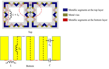
Fig. 7. The equivalent circuit of the unit cell of the proposed FSS.
Because transmission coefficients with excitation from –z and +z directions are the same, the results for –z direction are used in the following discussion and analysis. The comparison of transmission coefficients between 2.5-D FSS and plane FSS with the same size for normally incident plane wave is represented in Figure 8. As shown in Figure 8, the resonance frequency of the 2.5-D FSS is lower than that of plane square-loop FSS, which validates the previous analysis. Hence, the band characteristics can be adjusted by changing the total perimeter of the 2.5-D square loop. Compared with the design in [4] with size of 0.46 0.46, the unit cell of the proposed FSS has a more compact size of 0.097 0.097. This indicates that the proposed FSS achieves the structure miniaturization.
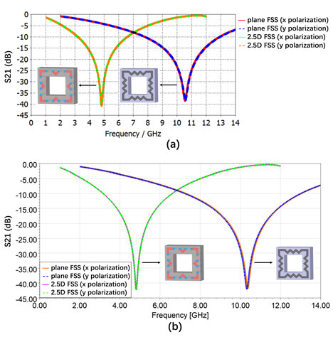
Fig. 8. Comparison of transmission coefficients between 2.5-D FSS and plane FSS at normal incidence simulated by (a) CST and (b) HFSS.
The comparison of transmission coefficients between 2.5-D FSS and a metal plate with hole at normal incidence with excitation from –z direction is illustrated in Figure 9. It can be seen that there is not much difference between two S21 values at 4.83 GHz. However, in the case of similar shielding performance, the proposed FSS with FR-4 lossy substrate is much lighter than a metal plate with the same size, which is more suitable for small lightweight electronic products.
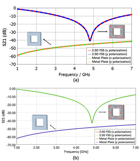
Fig. 9. Comparison of transmission coefficients between 2.5-D FSS and a metal plate at normal incidence simulated by (a) CST and (b) HFSS.
Table 3: Comparison with other structures in published literature
| FSS | Holes | Size () | Attenuation | Bandwidth | Stability |
| [26] | Without | 0.30 | 40 dB | Not reported | 45 |
| [17] | Without | 0.08 | 20 dB | Not reported | 60 |
| [18] | Without | 0.037 | 30 dB | Not reported | 60 |
| [20] | Without | 0.125 | 35 dB | 400 MHz (–20 dB) | 60 |
| [21] | Without | 0.216 | 20 dB | Not reported | 45 |
| [22] | Without | 0.088 | 35 dB | 315 MHz (–15 dB) | 60 |
| [23] | Without | 0.069 | 40 dB | 950 MHz (–10 dB) | 60 |
| [4] | With | 0.458 | 40 dB | 2 GHz (–30 dB) | 60 |
| Proposed | With | 0.097 | 40.74 dB | 3.38 GHz (–10 dB) | 85 |
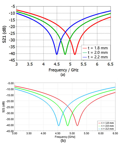
Fig. 10. Influence of dielectric thickness on transmission coefficients simulated by (a) CST and (b) HFSS simulator.
The relative dielectric constant of the dielectric substrate is 4.3, and the thickness t of the dielectric substrate changes from 1.8 to 2.2 mm at 0.2-mm intervals to investigate the influence of dielectric substrate thickness. Because the results for x-polarization and y-polarization at normal incidence from –z and +z directions are the same, the results for x-polarization at normal incidence from –z direction are taken as an example to be analyzed and shown in Figure 10. When the thickness of the dielectric substrate increases, the resonance frequency will decrease due to the inductance and capacitance contributed by vias.
Finally, the comparison between the proposed 2.5-D FSS and the results from published literature are listed in Table 3. It can be seen from Table 3 that the proposed 2.5-D FSS shows excellent performance in miniaturization. Especially compared with the FSS with holes [4], the unit cell size is significantly reduced. The proposed FSS has a large attenuation bandwidth, which is about 3.56 times larger than that in [23]. A Compact and High-Performance Shielding Enclosure by Using Metamaterial Design. In addition, the proposed 2.5-D FSS has small S21 and the angular stability is up to 85.
IV. CONCLUSION
An effective and novel metamaterial structure is proposed for 5G electromagnetic shielding. It provides 40.74 dB attenuation and 3.38-GHz bandwidth to suppress interference signals operating near 4.83 GHz. In particular, the proposed FSS overcomes the difficulty that the heat dissipation of the metal shielding deteriorates significantly for small apertures. It demonstrates the advantage of high shielding performance, small size, and excellent heat dissipation. This design can be further extended to the application of WLAN, ISM, GSM, and Wi-Fi shielding.
ACKNOWLEDGMENT
This work was supported by the National Natural Science Foundation of China under Grant 61771069 and National Key Laboratory on Electromagnetic Environment Effects under Grant A03B07C01-202002D0.
REFERENCES
[1] C. R. Paul, Introduction to Electromagnetic Compatibility, John Wiley & Sons, vol. 184, pp. 3-48, Jan. 2006.
[2] L. H. Hemming, Architectural Electromagnetic Shielding Handbook: A Design and Specification Guide, pp. 7-11, John Wiley & Sons, Aug. 2000.
[3] H. W. Ott, Electromagnetic Compatibility Engineering, John Wiley & Sons, pp. 238-300, Sep. 2011.
[4] L. Yan, L. Xu, X. Zhao, and R. X.-K. Gao, “An angularly stable frequency selective surface with vent holes for 5G electromagnetic shielding,” in 2019 IEEE International Symposium on Electromagnetic Compatibility-EMC EUROPE, pp. 366-369, Sep. 2019.
[5] M. Masud, B. Ijaz, A. Iftikhar, M. Rafiq, and B. Braaten, “A reconfigurable dual-band metasurface for EMI shielding of specific electromagnetic wave components,” in 2013 IEEE International Symposium on Electromagnetic Compatibility, pp. 640-644, Aug. 2013.
[6] F. Li, J. Han, and C. Zhang, “Study on the influence of PCB parameters on the shielding effectiveness of metal cavity with holes,” in 2019 IEEE 3rd Information Technology, Networking, Electronic and Automation Control Conference (ITNEC), pp. 383-387, Mar. 2019.
[7] J. Bai, Y. Gao, Y. Shen, and D. Shi, “Shielding effectiveness of an enclosure with PCB,” in 2009 IEEE 5th Asia-Pacific Conference on Environmental Electromagnetics, pp. 130-134, Sep. 2009.
[8] T. Otoshi, “A study of microwave leakage through perforated flat plates (short papers),” IEEE Transactions on Microwave Theory and Techniques, vol. 20, no. 3, pp. 235-236, Mar. 1972.
[9] B. Archambeault and C. Brench, “Shielded air vent design guidelines for EMI modeling,” in 1993 IEEE International Symposium on Electromagnetic Compatibility, pp. 195-199, Aug. 1993.
[10] M. Li, J. Nuebel, J. L. Drewniak, R. E. DuBroff, T. H. Hubing, and T. P. Van Doren, “EMI from airflow aperture arrays in shielding enclosures-experiments, FDTD, and MoM modeling,” IEEE Transactions on Electromagnetic Compatibility, vol. 42, no. 3, pp. 265-275, Aug. 2000.
[11] H. W. Ott and H. W. Ott, Noise Reduction Techniques in Electronic Systems, Wiley, New York, vol. 442, pp. 4-16, May 1988.
[12] R. Natarajan, M. Kanagasabai, S. Baisakhiya, R. Sivasamy, S. Palaniswamy, and J. K. Pakkathillam, “A compact frequency selective surface with stable response for WLAN applications,” IEEE Antennas and Wireless Propagation Letters, vol. 12, pp. 718-720, May 2013.
[13] H. AlKayyali and N. Qasem, “Convoluted frequency selective surface wallpaper to block the industrial, scientific, and medical radio bands inside buildings,” American Academic & Scholarly Research Journal, vol. 5, no. 3, p. 106, Apr. 2013.
[14] R. Sivasamy, L. Murugasamy, M. Kanagasabai, E. F. Sundarsingh, and M. G. N. Alsath, “A low-profile paper substrate-based dual-band FSS for GSM shielding,” IEEE Transactions on Electromagnetic Compatibility, vol. 58, no. 2, pp. 611-614, Feb. 2016.
[15] Y. Mannaa and R. W. Aldhaheri, “New dual-band frequency selective surface for GSM shielding in secure-electromagnatic buildings using square loop fractal configurations,” in 2016 16th Mediterranean Microwave Symposium (MMS), pp. 1-4, IEEE, Nov. 2016.
[16] T. Hussain, Q. Cao, J. K. Kayani, and I. Majid, “Miniaturization of frequency selective surfaces using 2.5-D knitted structures: design and synthesis,” IEEE Transactions on Antennas and Propagation, vol. 65, no. 5, pp. 2405-2412, Feb. 2017.
[17] C.-N. Chiu and W.-Y. Wang, “A dual-frequency miniaturized-element FSS with closely located resonances,” IEEE Antennas and Wireless Propagation Letters, vol. 12, pp. 163-165, Feb. 2013.
[18] D. Li, T. Li, and E. Li, “Implementation of ultra-miniaturised frequency-selective structures based on 2.5 D convoluted segments,” Electronics Letters, vol. 54, no. 8, pp. 476-478, Apr. 2018.
[19] P. Zhao, Y. Zhang, R. Sun, W.-S. Zhao, Y. Hu, and G. Wang, “Design of a novel miniaturized frequency selective surface based on 2.5-dimensional Jerusalem cross for 5G applications,” Wireless Communications and Mobile Computing, vol. 2018, Apr. 2018.
[20] R. Natarajan, M. Kanagasabai, S. Baisakhiya, R. Sivasamy, S. Palaniswamy, and J. K. Pakkathillam, “A compact frequency selective surface with stable response for WLAN applications,” IEEE Antennas and Wireless Propagation Letters, vol. 12, pp. 718-720, May 2013.
[21] F.-C. Huang, C.-N. Chiu, T.-L. Wu, and Y.-P. Chiou, “Very closely located dual-band frequency selective surfaces via identical resonant elements,” IEEE Antennas and Wireless Propagation Letters, vol. 14, pp. 414-417, Oct. 2014.
[22] R. Sivasamy and M. Kanagasabai, “A novel dual-band angular independent FSS with closely spaced frequency response,” IEEE Microwave and Wireless Components Letters, vol. 25, no. 5, pp. 298-300, Apr. 2015.
[23] H. Wang, S. Qu, J. Wang, M. Yan, and L. Zheng, “Dual-band miniaturised FSS with stable resonance frequencies of 3.4/4.9 GHz for 5G communication systems applications,” IET Microwaves, Antennas & Propagation, vol. 14, no. 1, pp. 1-6, Jan. 2020.
[24] T.-K. Wu, Frequency Selective Surface and Grid Array, Wiley-Interscience, vol. 40, pp. 27-70, Jul. 1995.
[25] B. A. Munk, Frequency Selective Surfaces: Theory and Design, John Wiley & Sons, pp. 1-48, Apr. 2005.
[26] W. Kiermeier and E. Biebl, “New dual-band frequency selective surfaces for GSM frequency shielding,” in 2007 European Microwave Conference, IEEE, pp. 222-225, Oct. 2007.
BIOGRAPHIES

Keyi Cui was born in Heze, Shandong, China, in 1998. She is currently working toward the master’s degree in electronic engineering from the Beijing University of Posts and Telecommunications, Beijing, China. Her main research interests include metamaterial, metalens, and machine learning.

Dan Shi (Member, IEEE) received the Ph.D. degree in electronic engineering from the Beijing University of Posts & Telecommunications, Beijing, China, in 2008. She has been a Professor with the Beijing University of Posts & Telecommunications. Her interests include electromagnetic compatibility, electromagnetic environment, and electromagnetic computation.

Chi Sun was born in Xi’an, Shanxi, China, in 1996. He received the master’s degree in electronic engineering from the Beijing University of Posts and Telecommunications, Beijing, China, in 2021. His main research content is electromagnetic compatibility and theory, mainly in FSS design for shielding.

Xiaoyong Liu received the bachelor’s degree in radio technology and information system from Tsinghua University, Beijing, China, in 2002. He is currently working toward the Ph.D. degree in electronic science and technology from the Beijing University of Posts & Telecommunications, Beijing, China. His research interests include electromagnetic compatibility, testing and measurement, and radio frequency spectrum technology.
ACES JOURNAL, Vol. 36, No. 11, 1484–1491.
doi: 10.13052/2021.ACES.J.361113
© 2021 River Publishers