Switched Beam Antenna System for V2V Communication in 5G Applications
Allam M. Ameen1, 2, Mohamed I. Ahmed2, Hala Elsadek2, and Wagdy R. Anis1
1Electronics and Communication Department, Faculty of Engineering, Ain Shams University, Cairo 11566, Egypt
allamameen@eri.sci.eg, wagdyanis51@yahoo.com
2Microstrip Department, Electronics Research Institute, New Nozha, Cairo 11843, Egypt
miahmed@eri.sci.eg, helsadek@eri.sci.eg
Submitted On: June 29, 2021; Accepted On: October 10, 2021
Abstract
In this paper, a switched beam antenna system consists of four Vivaldi antennas for vehicle-to-vehicle communication is presented. The proposed design is realized on a substrate material of “Rogers 5880” with 0.508-mm substrate thickness. The antenna is designed to operate at a center frequency of 28 GHz with operating bandwidth of 1.463 GHz. An overall realized gain of 9.78 dBi is achieved at the intended center frequency. The proposed antenna is designed and simulated using CSTMWS. It is also fabricated using photolithography techniques and measured using R&S vector network analyzer. Good agreement is obtained between both CSTMWS and measured results.
Index Terms: Vivaldi antenna, intelligence transportation system (ITS), vehicle-to-vehicle (V2V) communication, switched beam antenna, 5G applications.
I. INTRODUCTION
Intelligence transportation system (ITS) is built depending on dedicated short range communication (DSRC) technology which presents a high reliability and a fast data transmission [1, 2, 3, 4, 5, 6, 7]. This system improves the road safety to avoid car accidents and reduce the traffic jam by sending all the information about the road to the drivers to make decisions. There are four classifications of V2X wireless communications: vehicle-to-vehicle (V2V), vehicle-to-personal (V2P), vehicle-to-infrastructure (V2I), and vehicle-to-network (V2N) [8, 9, 10, 11, 12, 13, 14]. A low-profile monopolar was introduced and two antenna designs were presented: low-profile and flush-mounted [15]. Both antennas were surrounded by a thin plastic radome. Four-element monocone broadband antenna for V2X wireless communication is introduced [16]. Three antennas were proposed and discussed in the cavity to offer a significant room for antennas and radio frequency [17]. A low-profile wideband monopolar antenna size is reduced by adding four tapered slots which make it applicable for vehicles and helmets [18]. Three antenna arrays consisting of 16 patches in each array were developed to operate at 61 GHz [19].
There are many techniques for beam switching that can be used to reconfigure the radiated beams [20, 21]. Some of them are traditional such as digital beamforming [22], butler matrix [23], and phased array antennas [24]. Narrow bandwidth, bulky structure, and complicated beamforming networks are disadvantages of these methods at microwave frequencies. Another method to satisfy the beam switching configuration is by using PIN diodes which are operated by DC controlled circuit [25, 26, 27, 28]. In [25], RF switch controlled by a microcontroller to feed a 2 2 array antenna is introduced.
In this paper, four switched beam Vivaldi antennas with single port are designed, simulated, and fabricated for V2V wireless communication system. The proposed antenna provides a full 360 coverage area with high gain and large distance compared with an omnidirectional one. The antenna is designed to operate at a frequency of 28 GHz for mm-wave and 5G applications.
II. PROPOSED ANTENNA DESIGN
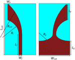
Figure 1 introduces the configuration of the proposed antenna structure. Four symmetric microstrip Vivaldi antennas are placed at different directions with an angle of 90 between each two antennas to cover the full 360 area. Five PIN diodes are used to connect the single port of the structure to each antenna. A controlled circuit is applied to switch the PIN diodes to ON/OFF states. Details of the single patch antenna and the overall structure are described below.
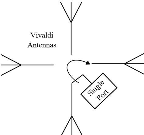
Fig. 1. Configuration of the proposed switched beam Vivaldi antennas.
Table 1: The dimensions of the proposed antenna element in the designed structure
| Parameter | Length (mm) | Parameter | Length (mm) |
| 32.25 | 16 | ||
| 9.581 | 0.705 | ||
| 13 | 1.65 | ||
| 8.75 | 4.25 | ||
| 9.775 | 28.825 |
A. Single microstrip Vivaldi antenna
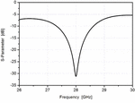
Figure 2 shows the design of the proposed Vivaldi antenna and its structure. The structure of the proposed antenna is realized by subtraction of an elliptical shape from the rectangular patch antenna on each side. The antenna is placed on a substrate of type “Roger 5880” with and 0.508-mm thickness. The overall antenna size for a single patch is . Table 1 shows the dimensions of the structure and all dimensions are in mm. The dimension of represents a minor radius of an ellipse which has a center at the edge of the substrate. Figure 3 shows the return loss of the single patch antenna.
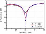
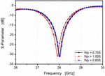
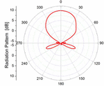
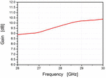
A parametric study is obtained for each dimension individually while the other parameters are constant. Figure 4 discusses the effect of changing the length of which tends to shift the resonance frequency and change the value of return loss (S). Increasing of tends to increase the resonance frequency and increase the return loss while the gain decreases. In Figure 5, increasing of tends to decrease the resonance frequency, while the return loss (S) approximately remains the same. Elaborating the results of all parametric studies, it is easy to choose the proper dimensions that achieve the resonant frequency at 28 GHz based on the required specifications and application. Figure 6 shows the radiation pattern of the proposed antenna at the resonant frequency. In Figure 7, the overall antenna gain for the single patch element is presented.
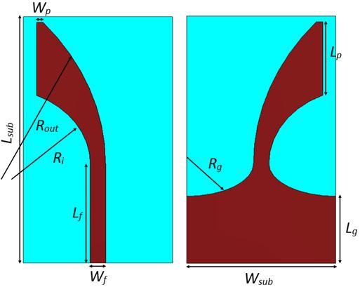
Fig. 2. The design of the proposed Vivaldi antenna and its structure.
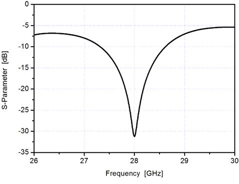
Fig. 3. The S-parameter (S) of the single patch antenna.
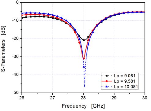
Fig. 4. A parametric study of increasing and decreasing of the length .
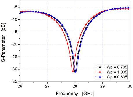
Fig. 5. A parametric study of increasing and decreasing of the length .

Fig. 6. The simulated radiation pattern of the single patch Vivaldi antenna.
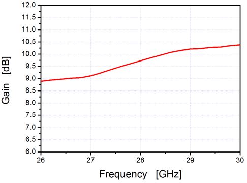
Fig. 7. The overall antenna gain for the single patch antenna.

Fig. 8. The complete proposed structure with four elements.
Table 2: Four configurations of the proposed antenna using switched RF diodes
| State | Switched Diodes | Radiator | ||||
| D1 | D2 | D3 | D4 | D5 | ||
| ON | OFF | OFF | OFF | OFF | Antenna 1 | |
| OFF | OFF | ON | OFF | ON | Antenna 2 | |
| OFF | OFF | ON | ON | OFF | Antenna 3 | |
| OFF | ON | OFF | OFF | OFF | Antenna 4 | |
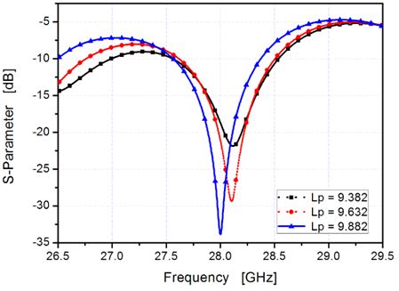
Fig. 9. A parametric study of increasing the length .
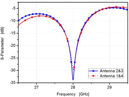
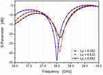
Fig. 10. The S-parameter (S) of the complete antenna structure: blue curve for antennas 2 and 3 and the red one for antennas 1 and 4.
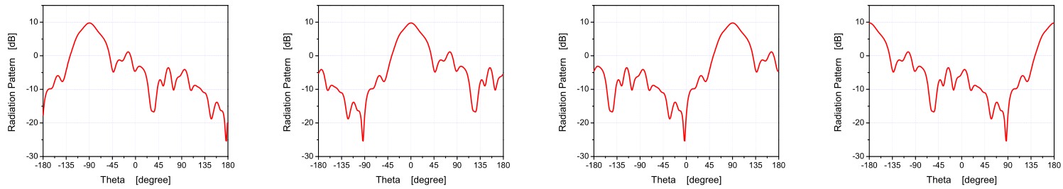
Fig. 11. The radiation pattern of the complete antenna structure: (a) antenna 2 is ON, (b) antenna 3 is ON, (c) antenna 4 is ON, and (d) antenna 1 is ON.
B. Proposed complete structure
The designed structure consists of four elements of the Vivaldi antenna designed. The four elements are constructed to cover the overall area by making the angle between any two elements equal to 90; so the overall coverage angle will be 360 as shown in Figure 8. The main benefit to use this structure instead of an omnidirectional antenna is the high gain and long distance that the signal can travel compared with the omnidirectional antenna. One microstrip feedline is used to feed the four elements. PIN diodes controlled by switching circuits are used to select the radiated antenna sequentially to transmit and receive the signals in all directions. PIN diodes offer a very good linearity and are applied for high power applications at microwave frequencies. An AlGaAs PIN diode of type “MA4AGBLP912” with a small ON-resistance, low capacitance, and significant fast switching speed is applied. The proposed structure is shown in Figure 8. The relationship between the switched RF diodes and the four radiator antenna structures is tabulated in Table 2. The shape of feedline is different in each case; so a parametric study for the shape of the feedline is presented in Figure 9. A groove between each two elements is used to enhance the system operation and improve the return loss. Table 3 shows additional dimensions for the proposed structure. In Figure 10, the return loss (S) of the four elements is shown. Figure 11 shows the radiation pattern of the proposed structure. In Figure 10 (a), for example, the diodes D3 and D5 are ON and D1, D2, and D4 are OFF, and then antenna 2 will operate and the radiation will be in the –90 direction. In Figure 10 (b), the diodes D3 and D4 are ON and D1, D2, and D5 are OFF, and then antenna 3 will operate and the radiation will be in the 0 direction and so on. The overall gain over the frequency range of operation for the full structure is studied.
Table 3: The dimensions of the overall proposed antenna structure
| Parameter | Length (mm) | Parameter | Length (mm) |
| 23.85 | 16 | ||
| 9.882 | 0.39 | ||
| 12 | 1.65 | ||
| 14.35 | 9.60 | ||
| 25 | 25 | ||
| 12.85 | 1.65 | ||
| 4.25 | 5.355 | ||
| 9.775 | 28.825 |
III. RESULTS AND DISCUSSION
A. Single element
The proposed single element Vivaldi antenna is designed and simulated by CST software. This structure is operated at a resonance frequency of 28 GHz to cover
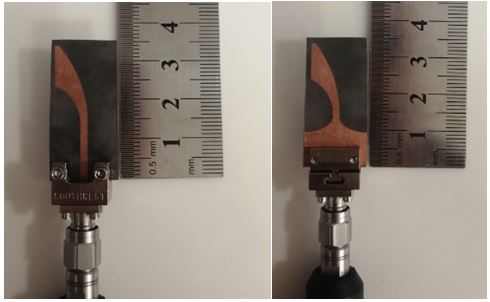
Fig. 12. The fabricated antenna design.
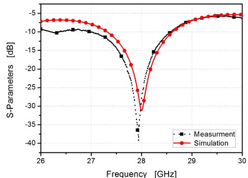
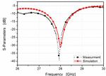
Fig. 13. The comparison of simulated and measured S results for single element antenna.
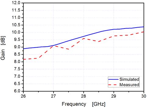
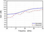
Fig. 14. The comparison between simulated and measured overall gain versus frequency results for the single element.
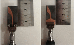
the ITS and 5G applications. It has a return loss of 31.5 dB at a resonance frequency. The antenna is fabricated using the photolithography method and measured using vector network analyzer (R&S ZVA 67). Figure 12 shows the fabricated single element antenna. Good agreement is achieved between the simulated and measured results.
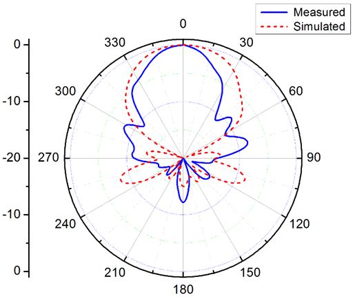
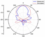
Fig. 15. The comparison between simulated and measured radiation patterns (normalized).


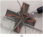
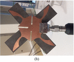
Fig. 16. The fabricated antenna structure: (a) top view; (b) bottom view.
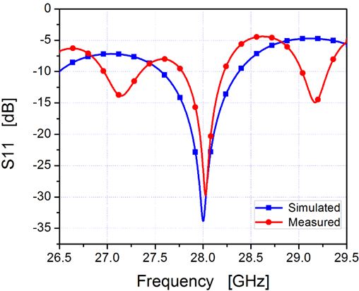
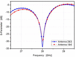
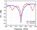
Fig. 17. The comparison of simulated and measured S results for antennas 1 and 4 in the complete structure.
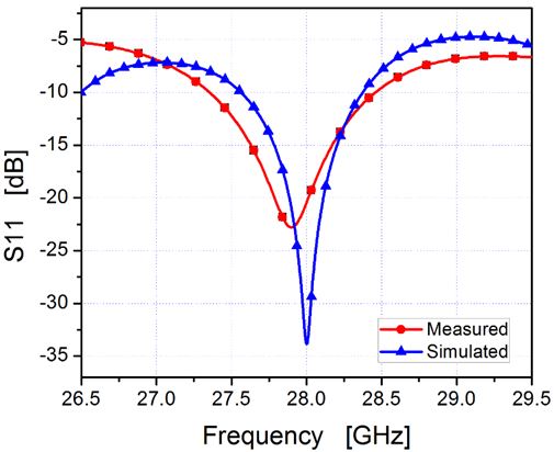
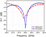
Fig. 18. The comparison of simulated and measured S results for antennas 2 and 3 in the complete structure.
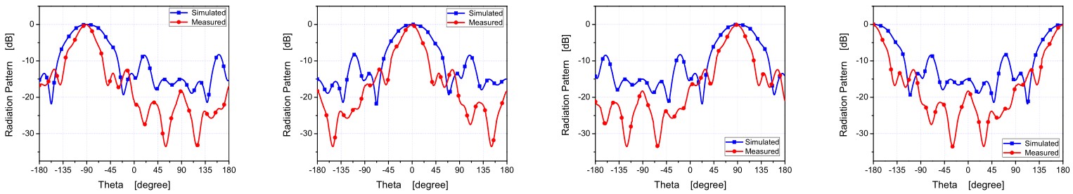
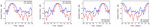
Fig. 19. The comparison between simulation and measurements of overall structure radiation pattern (normalized).
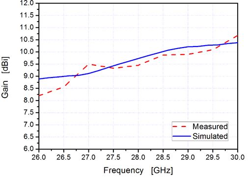
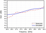
Fig. 20. The comparison between simulated and measured overall gain versus frequency results for a single element within the complete structure.
The return loss comparison curves are shown in Figure 13. The gain of the antenna is also measured and Figure 14 shows the comparison between measured and simulated results. The comparison between simulated and measured radiation pattern (normalized) is introduced as shown in Figure 15.
B. Complete structure
The complete antenna structure is designed on the same substrate of “Rogers 5880.” The complete antenna structure is fabricated and measured. Figure 16 shows the fabricated antenna structure. The return loss is measured and compared with the simulated one. Figure 17 shows the return loss for antennas 1 and 4 elements. The measured result is closed to the simulated one with some notches. Figure 18 shows the return loss for antennas 2 and 3 elements. The radiation pattern and the gain are also measured and compared with the simulated one. Good agreements are achieved between the simulated and measured results. Figure 19 shows the comparison between the simulated and measured radiation patterns. Figure 20 shows the overall gain versus frequency for the complete structure. The comparison between this work and previous works is tabulated in Table 4.
Table 4: Comparison with pervious works
| Paper | [15] | [16] | [18] | [19] | [20] | This Work |
| Center frequency [GHz] | 0.67 | 25.9 | 61 | 1 | 60 | 28 |
| Bandwidth (at –10 dB) [%] | 14.3 | 23.7 | 2.46 | 36 | 3.33 | 5.86 |
| Coverage area (degree) | 360 | 180 | 66 | 50 | 90 | 360 |
| Gain(dBi) | 5.8 | 6.1 | 18.7 | 9 | 3 | 9.78 |
| Size(in mm) | 144 144 | 570 220 | 46.4 31 | 250 250 | 14.7 11.9 | 48.85 48.85 |
IV. CONCLUSION
A switched beam antenna system that consists of four elements of Vivaldi antennas for V2V communication in 5G application is introduced. The designed antenna achieves a wide bandwidth of 5.38% around the operating center frequency of 28 GHz.
The omnidirectional radiation is achieved by using the four elements of Vivaldi antennas. The antenna shows remarkable radiation characteristics and a high gain of more than 9.78 dBi. The proposed antenna has achieved a bandwidth of 1.64 GHz for the single element and 1.11 GHz for the complete structure. The antenna is fabricated and measured.
REFERENCES
[1] S. Maddio, “A compact circularly polarized antenna for 5.8 GHz intelligent transportation system,” IEEE Antennas and Wireless Propagation Letters, vol. 16, no. 7, pp. 533-536, Jul. 2016.
[2] P. Singh, K. S. R. K. Chaitanya, and R. Kumari, “Microstrip patch antenna for application in intelligent transport systems,” TEQIP III Sponsored International Conference on Microwave Integrated Circuits, Photonics and Wireless Networks (IMICPW), Tiruchirappalli, India, 22-24 May 2019.
[3] Z.-P. Zhong, X. Zhang, J.-J. Liang, C.-Z. Han, M.-L. Fan, G.-L. Huang, W. Xu, and T. Yuan, “A compact dual-band circularly polarized antenna with wide axial-ratio beamwidth for vehicle GPS satellite navigation application,” IEEE Trans. Veh. Technol., vol. 68, no. 9, pp. 8683-8692, Sep. 2019.
[4] M. Chowdhury and K. C. Dey, “Intelligent transportation systems-a frontier for breaking boundaries of traditional academic engineering disciplines,” IEEE Intelligent Transportation Systems Magazine, vol. 8, no. 1, pp. 4-8, 2016.
[5] W. Wang, K. Guan, D. He, B. Ai, and Z. Zhong, “Channel characterization for vehicle-to-vehicle communication in urban sloped terrain,” International Applied Computational Electromagnetics Society Symposium - (ACES), Beijing, China, 29 July-1 Aug. 2018.
[6] L. Wen, S. Gao, Q. Luo, W. Hu, and Y. Yin, “Wideband dual circularly polarized antenna for intelligent transport systems,” IEEE Transactions On Vehicular Technology, vol. 69, no. 5, May 2020.
[7] W. Viriyasitavat, M. Boban, H. M. Tsai, and A. Vasilakos, “Vehicular communications: survey and challenges of channel and propagation models,” IEEE Veh. Technol. Mag., vol. 10, no. 2, pp. 55-66, Feb. 2015.
[8] C. Li, W. Chen, J. Yu, K. Yang, F. Li, and Y. Shui, “V2V radio channel properties at urban intersection and ramp on urban viaduct at 5.9 GHz,” IET Communications, vol. 12, no. 17, pp. 2198-2205, 2018.
[9] A. Liu and Y. Lu, “Low-profile patch antennas with enhanced horizontal omnidirectional gain for DSRC applications,” in IET Microwaves, Antennas & Propagation, vol. 12, no. 2, pp. 246-253, 2018.
[10] K. Wevers and M. Lu, “V2X communication for ITS-from IEEE 802.11p towards 5G,” IEEE 5G Tech Focus, vol. 1, no. 2, Jun. 2017.
[11] L. Huang and Y. Lu, “A switchable or MIMO antenna for V2X communication,” IEEE International Conference on Computational Electromagnetics (ICCEM), Shanghai, China, China, pp. 20-22, Mar. 2019.
[12] T. Fan, W. Chen, C. Li, X. Shu, and F. Chang, “Small scale characteristics analysis on highway V2V channel for intelligent transportation systems,” 5th International Conference on Transportation Information and Safety (ICTIS), Liverpool, United Kingdom, pp. 14-17, Jul. 2019.
[13] C.-H. Kuo, C.-C. Lin, and J.-S. Sun, “Modified microstrip franklin array antenna for automotive short-range radar application in blind spot information system,” IEEE Antennas and Wireless Propagation Letters, vol. 16, no. 2, pp. 1731-1734, Feb. 2017.
[14] S. F. Jilani and A. Alomainy, “A multiband millimeter-wave 2-D array based on enhanced franklin antenna for 5G wireless systems,” IEEE Antennas and Wireless Propagation Letters, vol. 16, no. 9, pp. 2983-2986, Sep. 2017
[15] N. Nguyen-Trong, S. P. Pinapati, D. Hall, A. Piotrowski, and C. Fumeaux, “Ultralow-profile and flush-mounted monopolar antennas integrated into a metallic cavity,” in IEEE Antennas and Wireless Propagation Letters, vol. 17, no. 1, pp. 86-89, Jan. 2018.
[16] M. W. Lee and N. S. Jeong, “Low-profile vehicle roof-top mounted broadband antenna for V2X,” Antennas and Propagation and USNC-URSI Radio Science Meeting 2019 IEEE International Symposium on, pp. 925-926, 2019.
[17] G. Artner, R. Langwieser, and C. F. Mecklenbräuker, “Concealed CFRP vehicle chassis antenna cavity,” in IEEE Antennas and Wireless Propagation Letters, vol. 16, pp. 1415-1418, 2017.
[18] N. Nguyen-Trong, A. Piotrowski, T. Kaufmann, and C. Fumeaux, “Low-profile wideband monopolar UHF antennas for integration onto vehicles and helmets,” in IEEE Transactions on Antennas and Propagation, vol. 64, no. 6, pp. 2562-2568, Jun. 2016.
[19] V. Semkin, F. Ferrero, A. Bisognin, J. Ala-Laurinaho, C. Luxey, F. Devillersand, and A. V. Räisänen, “Beam switching conformal antenna array for mm-wave communications,” IEEE Antennas and Wireless Propagation Letters, vol. 15, pp. 28-31, Apr. 2015.
[20] A. Darvazehban, S. A. Rezaeieh, and A. Abbosh, “Wideband beam-switched bow-tie antenna with inductive reflector,” IEEE Antennas and Wireless Propagation Letters, vol. 19, no. 10, pp. 1724-1728, Oct. 2020.
[21] K. Trzebiatowski, M. Rzymowski, L. Kulas, and K. Nyka, “Simple 60 GHz switched beam antenna for 5G millimeter-wave applications,” IEEE Antennas and Wireless Propagation Letters, vol. 20, no. 1, pp. 38-42, Jan. 2021.
[22] V. Venkateswaran, F. Pivit, and L. Guan, “Hybrid RF and digital beamformer for cellular networks: algorithms, microwave architectures, and measurements,” IEEE Trans. Microwave Theory Tech., vol. 64, no. 7, pp. 2226-2243, 2016.
[23] P. I. Bantavis, C. I. Kolitsidas, T. Empliouk, M. L. Roy, B. L. G. Jonsson, and G. A. Kyriacou, “A cost-effective wideband switched beam antenna system for a small cell base station,” IEEE Trans. Antennas Propag., vol. 66, no. 12, pp. 6851-6861, Dec. 2018.
[24] X. G. Zhang, W. X. Jiang, H. W. Tian, Z. X. Wang, Q. Wang, and T. J. Cui, “Pattern-reconfigurable planar array antenna characterized by digital coding method,” IEEE Trans. Antennas Propag., vol. 68, no. 2, pp. 1170-1175, Feb. 2020.
[25] Y.-X. Du, H. Liu, L. Qin, and B.-S. Li, “Integrated multimode orbital angular momentum antenna based on RF switch,” IEEE Access, vol. 8, pp. 48599-48606, Mar. 2020.
[26] A. Darvazehban, S. A. Rezaeieh, O. Manoochehri, and A. M. Abbosh, “Two-dimensional pattern-reconfigurable cross-slot antenna with inductive reflector for electromagnetic torso imaging,” IEEE Trans. Antennas Propag., vol. 68, no. 2, pp. 703-711, Feb. 2020.
[27] S. A. Rezaeieh, A. Zamani, and A. M. Abbosh, “Pattern reconfigurable wideband loop antenna for thorax imaging,” IEEE Trans. Antennas Propag., vol. 67, no. 8, pp. 5104-5114, Aug. 2019.
[28] H.-T. Chou, Y.-S. Chang, H.-J. Huang, Z.-D. Yan, T. Lertwiriyaprapa, and D. Torrungrueng, “Two-dimensional multi-ring dielectric lens antenna to radiate fan-shaped multi-beams with optimum adjacent-beam overlapping crossover by genetic algorithm,” IEEE Access, vol. 8, pp. 79124-79133, May 2020.
[29] CST Microwave Studio, ver. 2019, Computer Simulation Technology, Framingham, MA, 2019.
ACES JOURNAL, Vol. 36, No. 11, 1438–1445.
doi: 10.13052/2021.ACES.J.361107
© 2021 River Publishers