Comparative Study on Improved and Traditional Equivalent Circuit of Long Primary Double-Sided Linear Induction Motor
Qian Zhang, Hui-juan Liu, Zhen-yang Zhang, Teng-fei Song, and Yu Wang
School of Electrical Engineering, Beijing Jiaotong University, Beijing 100044, China
qianzh@bjtu.edu.cn, hjliu@bjtu.edu.cn, 16117375@bjtu.edu.cn, 18117020@bjtu.edu.cn, 20121498@bjtu.edu.cn
Submitted On: July 13, 2021; Accepted On: October 18, 2021
Abstract
Based on the quasi-two-dimensional (2D) field model of long primary double-sided linear induction motor (LPDLIM), an improved equivalent circuit model is proposed. First, the traditional equivalent circuit of LPDLIM is reviewed. Second, the skin effect correction coefficients for the secondary equivalent resistance and excitation reactance, and the secondary leakage inductance are derived. Moreover, an improved equivalent circuit model for LPDLIMs is presented, in which the leakage reactance of the secondary is considered, and the excitation reactance and secondary resistance are modified by the correction coefficients independently. Then, the slip frequency characteristics of various effect forces and variations of forces under different operations and mechanical air gap width are presented. Finally, the calculated forces by the proposed equivalent circuit are validated by the finite element method results and also compared with that of the traditional equivalent circuit model.
Index Terms: Double-sided linear induction motor, end effect, equivalent circuit, long primary, skin effect.
I. INTRODUCTION
Because the linear induction motor (LIM) has a wide range of speed and acceleration, it avoids the intermediate transmission mechanism of linear motion, reduces the mechanical loss and stress, and its system has high reliability [1]. The LIMs have been widely used in aircraft electromagnetic launch or accelerator system [2], transportation system [3, 4], loading and unloading system [5], etc.
The LIM has a different structure from the rotating induction motor (RIM), and the unique structure produces special effects, such as the longitudinal end effect, transverse edge effect, and so on, which will affect the thrust characteristics of the motor. The most commonly used methods to solve the thrust characteristics of LIM are finite element method (FEM) [6], numerical calculation method [7], equivalent circuit (or equivalent magnetic circuit) method [8, 9], and so on.
The FEM software is not only convenient for the optimization design of LIMs [10] but also provides convenience for the performance calculation of motor with special structure or with abnormal secondary position [11, 12]. However, due to the longitudinal end effect, it cannot build a partial pole pair FEM model of LIM like a RIM; a full model means that more computer resources and longer computing time are needed [13].
Among the analytical methods for solving the performance of linear motor, one-dimensional (1D) field analytical method is the most used [14], while two-dimensional (2D) and three-dimensional (3D) fields are more accurate to solve the performance [15, 16, 17].
The analytical solution is helpful to understand the field distribution clearly, but it cannot directly reflect the impedance of the motor as the equivalent circuit. The end and edge effects, which play a significant role in the performance of a LIM, are reflected in the equivalent circuit by modifying factors on the impedance [9]. In addition to Duncan’s equivalent circuit [18], T-type equivalent circuit based on field theory is another common model. The equivalent circuit of SLIM has been deeply studied because of its application as traction motor [9]. However, because the secondary of double-sided LIM (DLIM) is usually only a conductive plate, while that of SLIM has back iron, their equivalent circuits are different.
The research of the equivalent circuit of DLIM is far less extensive than that of SLIM for its limited application. In the conventional equivalent circuit of the long primary double-sided LIM (LPDLIM), the longitudinal end effect and transverse edge effect of motor are demonstrated by correction factors of secondary resistance and excitation reactance, and the secondary leakage reactance is neglected [14, 19]. In the high-speed applications, an equivalent circuit with only longitudinal end effect may be enough to analyze the performance of the LPDLIM [14, 20].
In addition to the end/edge effect, the secondary leakage reactance and the skin effect of the secondary will have an important impact on the performance of the low-speed LPDLIM with the large air gap. Although the impedance parameters with skin effect of the equivalent circuit can be obtained by 2D and 3D field analyses, their expressions are very complex [21]. In the above equivalent circuit model for LPDLIM, few papers take the skin effect into the equivalent circuit.
In this paper, quasi-2D model is built to analyze the inhomogeneous distribution of air gap flux density in vertical direction, that is, the skin effect and secondary leakage reactance are considered in the equivalent circuit to make it more perfect. In Section II, the correction factors of longitudinal end and transverse edge effects on the equivalent circuit impedance are given. And then the conventional equivalent circuit in the coupling region of the LPDLIM is presented. In Section III, the skin effect factors of modified secondary equivalent resistance and excitation reactance, and secondary leakage reactance are derived. And the improved equivalent circuit model for LPDLIMs is proposed. In Section IV, the slip frequency characteristics of various effect forces are presented. The results of 3D FEM are used to verify the proposed equivalent circuit model, and also compared with that of the traditional equivalent circuit model. Finally, the conclusions are summarized in Section V.
II. TRADITIONAL T-TYPE EQUIVALENT CIRCUIT
The 3D LPDLIM was developed and is presented in Figure 1. The model is usually decomposed into two independent analytical models, namely, the longitudinal (x-axis) analysis model (Figure 1 (b)) considering the longitudinal end effect, and the transversal (z-axis) analysis model (Figure 1 (c)) considering the transverse edge effect. In the 1D field analysis theory for LPDLIMs, the longitudinal end effect and transverse edge effect can be considered to act independently or be neglected.
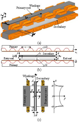
Fig. 1. (a) 3D model of LPDLIM. (b) Longitudinal analysis model. (c) Transversal analysis model.
A. Longitudinal end effect
The longitudinal 1D analysis model is shown in Figure 1 (b). In order to simplify the analysis model considering longitudinal end effects, the assumptions are presented as [14].
Taking the secondary as the motion reference coordinate [22], according to the fact that the equal complex power between the magnetic field and the electrical circuit, the secondary resistance and excitation reactance per phase with end effect neglected can be calculated by the following equation [14]:
| (1) |
where m is the number of primary phases, W is the number of turns of the primary per phase winding in series, k is the primary winding coefficient, a is the half width of primary core, p is the number of the pole pairs, is the pole pitch, is the surface conductivity of the secondary, and G is the quality factor.
The longitudinal end effect factors are denoted as eqn (2) [14], where K and K are the correction factors for the secondary resistance and the magnetizing reactance, respectively
| (2) |
where k and k are the functions of slip s and quality factor G and L is the secondary length, which is the same as the segmented primary length L= 2p in this paper.
B. Transversal edge effect
The transversal analysis model is shown in Figure 1 (c). The longitudinal end effect is neglected in solving the transverse edge effect, and some assumptions are made in deriving the field equations [19].
The correction factors of the transverse edge effect C and C are given by [19, 21]
| (3) |
These correction factors of transverse edge effect are also used to modify the secondary resistance and excitation reactance, respectively, where T is the function of the slip, quality factor, and motor structure parameters [19].
| (4) |
where r, , and are given as eqn (5) [19], and k = /,
| (5) |
The transverse edge effect may be accounted for by introducing a larger equivalent primary stack width 2a instead of actual width 2a, and a = a + k (d + g), and range of the coefficient k is 0.61 [23]. The new correction factors C and C of transverse edge effect can be obtained by replacing the actual core width with the new equivalent stack width in eqn (3)(5).
C. Traditional equivalent circuit
The specifications of the LPDLIM are listed in Table 1, and frequency of operation is 60 Hz.
Table 1: Specifications of the LPDLIM
| Quantity | Symbol | Value |
| Number of phases | m | 3 |
| Number of poles | 2p | 6 |
| Number of slots per phase per pole | q | 2 |
| Pole pitch | 66 mm | |
| Segmented primary length | L | 396 mm |
| Primary width | 2a | 70 mm |
| Mechanical air gap length | g | 27 mm |
| Secondary thickness | 2d | 3 mm |
| Secondary width | 2c | 140 mm |
| Secondary length | L | 396 mm |
The longitudinal end effect and transverse edge effect factors are calculated in Figure 2. The factor of secondary resistance corrected by the longitudinal end effect increases with slip frequency, while the factor of modified excitation reactance decreases with slip frequency, that is, the longitudinal end effect increases the secondary resistance and reduces the excitation reactance. The distribution of transverse edge effect factors is similar to that of longitudinal end effect but have smoother trend. In the new correction factors of transverse edge effect calculated by equivalent primary width 2a, the factor of modified secondary resistance C is reduced, while the correction factor of excitation reactance C is basically unchanged, compared with the traditional ones.
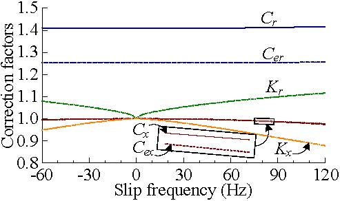
Fig. 2. Correction factors for longitudinal end effect and transverse edge effect.
The T-model equivalent circuit is shown in Figure 3 since the LPDLIM is usually segmented supplied. The coupling coefficient between the secondary and the nth primary is defined as
| (6) |
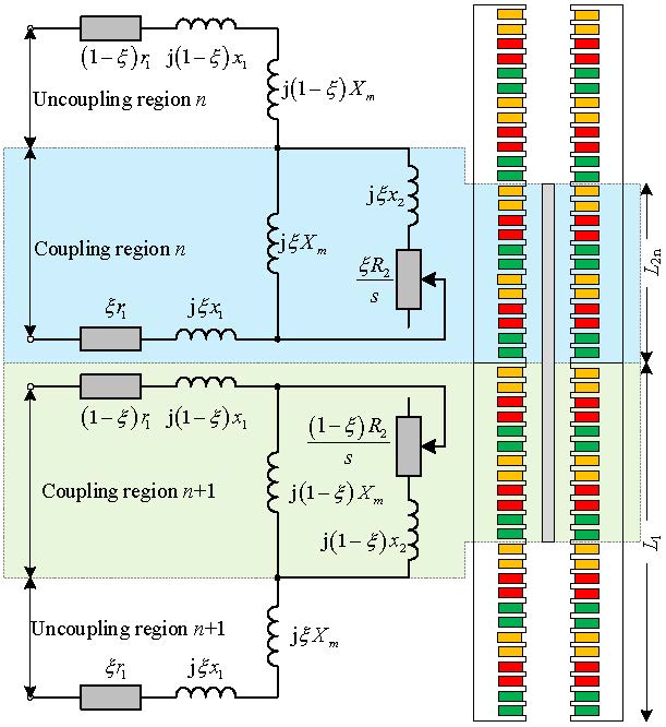
Fig. 3. Equivalent circuit of LPDLIM with primary windings in series.
where L is the coupling length between the secondary and the nth primary. Because the length of the secondary is equal to that of the primary, the coupling coefficient between the secondary and the (n + 1)th primary is 1 .
Here, r and x are the phase resistance and leakage reactance of one segment primary, X is the excitation reactance of primary and secondary fully coupled ( = 1), and R and x are the equivalent phase resistance and leakage reactance of secondary. The excitation reactance and secondary resistance in Figure 3 can be end/edge effect considered or not.
When the windings of the LPDLIM with segmented supplied are in series, the equivalent circuit of the coupling region introducing the longitudinal end effect and the transverse edge effect correction factors can be simplified as shown in Figure 4 due to the same currents of the two stator windings. The excitation reactance and secondary resistance without end (edge) effect of the coupling region are x and r, respectively. In the traditional equivalent circuit, the secondary leakage reactance is usually ignored, i.e., x 0.
When factors C and C are used to replace the traditional transverse edge effect correction factors C and C in Figure 4, a new equivalent circuit (EC-LTe) can be used to calculate the characteristics of a LPDLIM.
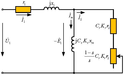
Fig. 4. Traditional equivalent circuit with longitudinal end effect and transverse edge effect (EC-LT).
III. IMPROVED EQUIVALENT CIRCUIT MODEL
In the traditional equivalent circuit of LPDLIMs, longitudinal end effect and transverse edge effect, or one of them, are usually considered.
As it knows, the field distribution of linear motor is 3D. In order to consider the influence of field distribution in each direction on the impedance parameters of equivalent circuit, the 3D motor model is divided into three independent direction models, namely longitudinal, transversal, and vertical analysis models. Each model is analyzed separately to obtain the corresponding correction coefficient of impedance. A full equivalent circuit model considering the longitudinal, transverse, and vertical field distribution is obtained.
A. Correction factors for skin effect and secondary leakage reactance
As in Section II, for example, when solving the longitudinal end effect, it is considered that the transverse edge effect does not exist, that is, the transverse width (y-direction) is infinite, and the air gap magnetic field is evenly distributed in the vertical direction (z-axis). In this section, the longitudinal and transverse end effects are negligible; only the influence of inhomogeneous distribution of the air gap magnetic field in the vertical direction (y-axis), i.e., the skin effect on the thrust characteristics of the motor, is further considered. The correction factors of the excitation reactance and secondary resistance caused by the inhomogeneous distribution of the air gap flux vertically are solved based on the quasi-2D electromagnetic field.
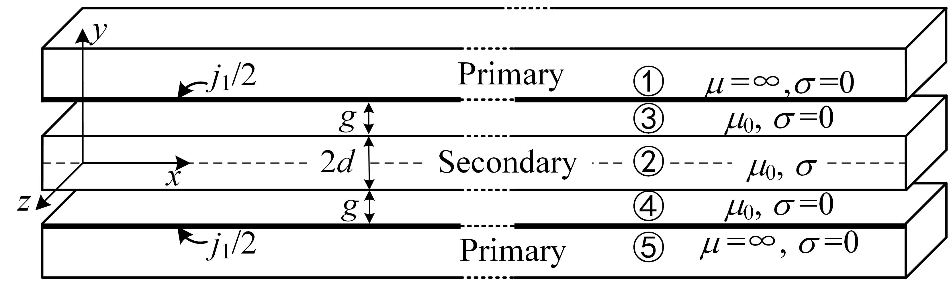
Fig. 5. Vertical analysis model of skin effect.
The quasi-2D representation of the LPDLIM is shown in Figure 5. To simplify the analytical model, the following assumptions are made [7, 9, 15].
1. The primary core is not saturated, and the resistivity of the primary core is infinite.
2. The primary and secondary are infinitely long in the motion direction and wide enough transversally.
3. Both primary and secondary currents have only z-component, and the primary currents flow in infinitesimally thin sheets.
Based on the theory of the LPDLIM and the Maxwell’s equations, the vector magnetic potential equation of the electromagnetic field of the motor is [21]
| (7) |
where A is the vector magnetic potential, is the air magnetic permeability, is the conductivity of the secondary, and v is the relative velocity of primary and secondary. According to the above assumptions, A has only the z-direction component and can be defined as
| (8) |
In regions 2 (secondary) to 4 (air gap), the following equation is obtained:
| (9) |
Undetermined magnetic potential A (i = 2, 3, 4) are solved by the satisfactions of the boundary conditions among primary, air gap, and secondary.
The electric field intensity in the air gap and the secondary is denoted by
| (10) |
The electromagnetic complex power transferred from the primary to the air gap and secondary can be calculated as follows [21]:
| (11) |
where j is the primary surface current density, g is the electromagnetic air gap width, and g= d + g, d is the half thickness of secondary, and g is the mechanical air gap width.
There is no active power and reactive power in the secondary when slip is 0, and the complex power calculated by eqn (11) only has the reactive power on the exciting reactance, i.e., S = jQ. Therefore, the excitation reactance with inhomogeneous air gap magnetic field in the vertical direction considered can be obtained by the following expression:
| (12) |
where K is the correction factor of the skin effect on excitation reactance with end effect neglected
| (13) |
When the slip is not 0, in the T-type equivalent circuit, the following relationship is satisfied [21]:
| (14) |
where P and Q are the active power and reactive power in the secondary, respectively, and is the conjugate current of the secondary branch reduced to the primary.
The secondary resistance and leakage reactance considering inhomogeneous air gap magnetic field in the vertical direction can be calculated by
| (15) |
| (16) |
where K is the correction factor of the secondary resistance without end effect. The secondary leakage reactance x can be expressed by the excitation reactance without end effect
| (17) |
| (18) |
where the constants C, C, D, and D are the functions of slip frequency, and motor parameters, such as secondary thickness 2d, mechanical air gap width g, pole pitch , etc.
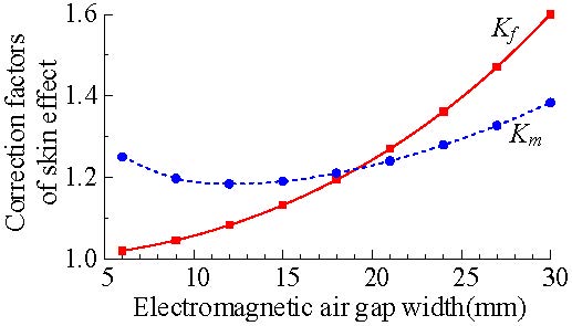
Fig. 6. Correction factors for skin effect.
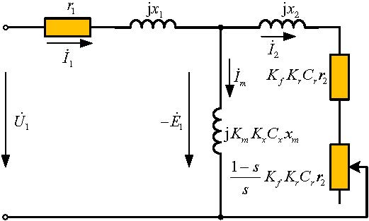
Fig. 7. Improved equivalent circuit with longitudinal end effect, transverse edge effect, inhomogeneous air gap magnetic field in vertical direction, and secondary leakage reactance (EC-LTS).
The calculation results show that these two correction factors (K and K) are determined by the parameters of the LPDLIM, e.g., the electromagnetic air gap width, and independent of slip frequency. With the secondary thickness of 3 mm, these two factors versus the width of the electromagnetic air gap g are shown in Figure 6. They both increase the secondary resistance and excitation reactance although their trends are different.
B. Improved equivalent circuit
Based on the traditional equivalent circuit in Figure 4, the derived correction factors K and K are used to modify the excitation reactance and secondary resistance, respectively, and the secondary leakage reactance is connected in series with the modified secondary resistance in the secondary branch circuit; an improved equivalent circuit (EC-LTS) for LPDLIM as shown in Figure 7 is obtained. Similarly, if the traditional transverse edge effect factors C and C in Figure 7 are replaced with the C and C, respectively, another T-type equivalent circuit (EC-LTeS) can be obtained to solve the performance of the LPDLIM.
In the improved equivalent circuit, the end effect in the longitudinal direction, the edge effect in the transverse direction, and the inhomogeneous air gap magnetic field in the vertical direction are considered. The mechanical power of LPDLIM with all effects considered is expressed as follows [24]:
| (19) |
| (20) |
IV. COMPARATIVE STUDY ON IMPROVED AND TRADITIONAL EQUIVALENT CIRCUIT
A. Circuit parameters
The excitation reactance and secondary resistance without any end effect, as shown in eqn (1), are only functions of the parameters of the motor, while they are also functions of the slip frequency after considering the longitudinal end effect, transverse edge effect, and vertical magnetic field distribution
| (21) |
| (22) |
where the one with “LT” in the subscript is the equivalent impedance including longitudinal end and transverse edge effects, and the impedance with “LTS” in the subscript also takes into account the inhomogeneous magnetic field vertically.
Figure 8 (a) shows the calculation curves for the rectified excitation inductance and secondary resistance versus the slip frequency. The longitudinal end and transverse edge effects reduce the excitation inductance and increase the secondary resistance in the equivalent circuit, and the skin effect increases both the excitation inductance and secondary resistance.
The parameter with “LTe” and “LTeS” in the subscript represents the equivalent resistance or excitation inductance calculated by using the equivalent primary width 2a. The new transverse edge effect factors mainly reduce the secondary resistance, while the excitation inductance remains unchanged, which is compared with the corresponding impedance calculated by the actual primary width 2a.
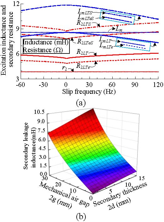
Fig. 8. (a) Modified excitation inductance and secondary resistance under different slip frequencies. (b) Secondary leakage inductance with different secondary thickness 2d and air gap width 2g.
The secondary leakage inductance with respect to the secondary thickness 2d and air gap width 2g is given in Figure 8 (b). The secondary leakage inductance increases with the increase of mechanical air gap and secondary thickness. For the DLIM with large mechanical air gap, the secondary leakage reactance may not be ignored in the equivalent circuit.
B. End effect and skin effect force
It has been proved that the longitudinal end effect can produce a certain braking force or thrust in the motoring region by the thrust analytical calculation [22]. If the correction factors of the longitudinal end effect and the transverse edge effect in Figure 4 are 1, the normal traveling wave thrust without any end effects can be calculated. When the transverse edge effect factors are 1, the thrust with longitudinal end effect can be calculated. The longitudinal end effect force varies with slip frequency in the whole operation region, as shown in Figure 9 (a), in which the secondary thickness is 3 mm and the mechanical air gap width changes from 9 to 27 mm.
In the motoring region (060 Hz), the longitudinal end effect force is the braking force, and the force reaches the peak and then decreases with an increase of the slip frequency; in the generating region (60 to 0 Hz), the longitudinal end effect force becomes a kind of thrust; when it enters the negative braking region (60120 Hz), the force is mainly a braking force, and the descending slope is smoother. When the slip frequency is 0 Hz, there is no end longitudinal effect, and the longitudinal end effect force is 0 N.
The transverse edge effect force can be calculated by a similar method. The transverse edge effect force and longitudinal end effect force have similar distribution characteristics. It is shown as braking force in motoring region and thrust force in generating region. The force reaches the peak rapidly and then decreases with an increase of the slip frequency, in the region of high slip frequency, the force changes gently. The new transverse edge effect factors reduce the transverse edge effect force in most slip frequency range, compared with the traditional ones.
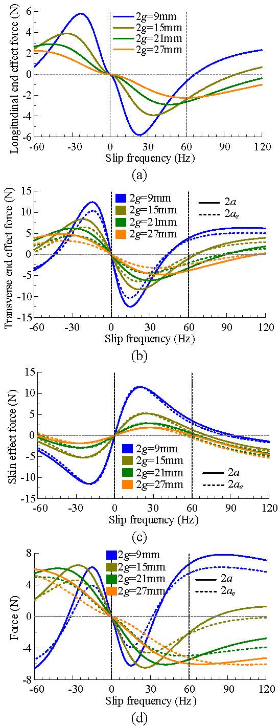
Fig. 9. Forces versus slip frequency with different mechanical air gap width 2g. (a) Longitudinal end effect force. (b) Transverse edge effect force. (c) Skin effect force. (d) Resultant of force produced by various effects.
The force produced by the inhomogeneous distribution of the vertical air gap magnetic field, i.e., the skin effect force, is basically opposite to the longitudinal end effect force in the whole slip frequency range. That is, in the generating region, the skin effect force is the braking force, and in the motoring region, it is the thrust force. At high slip frequency, for the motor with large air gap, it is the braking force that increases approximately linearly with the slip frequency. The new transverse end effect coefficient has little effect on the skin effect force basically.
The maximum values of longitudinal end effect force, transverse end effect force, and skin effect force decrease with the increase of air gap, which is due to the decrease of magnetic flux density at the secondary surface with the increase of air gap width.
The frequency characteristics of total force (i.e., the sum of longitudinal end effect force, transverse end effect force, and skin effect force) generated by various effects are shown in Figure 9 (d). For the LPDLIM with small air gap, e.g., the air gap width is 9 mm, the resultant force at low slip frequency is the braking force in the motoring region and is the thrust force in the generating region. When the slip frequency is higher than 40 Hz, the resultant force increases the output thrust of the motor based on the normal traveling wave thrust. For the large air gap LPDLIM, the resultant force gradually increases to the maximum and then decreases with the increase of slip frequency under both the motoring and generating conditions. With the increase of the air gap width, the slope of resultant force curve decreases in the low slip frequency range. The new transverse edge effect coefficients reduce the resultant force in the motoring and generating regions.
Although the maximum resultant forces of various effects are similar in different air gaps, it should be noted that the normal traveling wave thrust without various effects increases sharply with the decrease of air gap. Therefore, for the large air gap LPDLIM, the resultant forces of various effects play a very important role in the total electromagnetic thrust.
C. Thrust characteristics
The electromagnetic thrust calculated by FEM 3D model (Figure 10) is used to verify the improved equivalent circuit model, and the simulation results are also used to compare with that of the traditional equivalent circuit with longitudinal end effect and transverse edge effect.
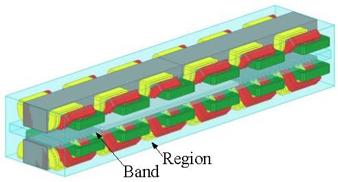
Fig. 10. 3D FEM of the LPDLIM.
The 3D FEM model of the LPDLIM is performed using ANSYS 18.0, and the motor parameters used in the simulation model are listed in Table 1. The frequency of the power supply is 60 Hz, the current is 6.85 A, and the mechanical air gap widths are 9, 15, and 27 mm, respectively.
The thrust characteristic curves calculated by various equivalent circuit models are shown in Figure 11, and the 3D FEM simulation results are also shown in the figure. In the operation region of both motoring and generating regions, the force calculated by improved equivalent circuits are in good agreement with the 3D simulation results, while the calculation results of traditional equivalent circuit are obviously different from the simulation ones. Although there are slight differences between the characteristic curves calculated by the equivalent circuit model EC-LTeS (with new transverse edge effect coefficients C and C) and EC-LTS (with transverse edge effect coefficients of C and C), the results of 3D simulation are closer to those of the equivalent circuit model EC-LTeS.
In the negative braking region, there is little difference between the results of the two equivalent circuits. The results of 3-D calculation seem to be closer to those of the equivalent circuit model EC-LT.
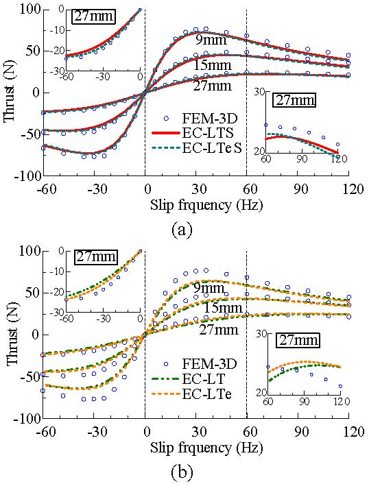
Fig. 11. Thrust characteristics of different mechanical air gap widths 2g solved by equivalent circuit model of (a) EC-LTS and EC-LTeS and (b) EC-LT and EC-LTe.
The thrust calculation errors are presented in Figure 12. In the negative braking region, the calculation errors of the equivalent circuit model EC-LTS are smaller than that of EC-LTeS, but they are almost the same as the traditional equivalent circuit models.
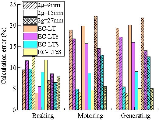
Fig. 12. Calculation error with various equivalent circuit models and operating regions.
In the motoring and generating operation regions, the traditional equivalent circuit models (EC-LT and EC-LTe) have large errors, even more than 15%. Although the new transverse end effect coefficient circuit model EC-LTe can reduce the error to a certain extent, the calculation errors are still more than 10%. When the mechanical air gap of the LPDLIM is small, e.g., 2g = 9 mm, the calculation error of the equivalent circuit model EC-LTS and EC-LTeS are almost the same, but for the large air gap motor, the errors of the EC-LTeS model are significantly reduced. This is because the electromagnetic air gap becomes larger, and the air gap magnetic field extends further in the lateral direction.
V. CONCLUSION
The quasi-2D field model of the motor is established, and the secondary leakage reactance is solved, an improved equivalent circuit model for LPDLIM with the inhomogeneous distribution of air gap flux density vertically considered based on conventional equivalent circuits is proposed. By comparing the calculation results of the FEM 3D with those of the traditional and the improved equivalent circuits, conclusions include the following.
1. When skin effect is considered to the equivalent circuit of LPDLIM, the secondary resistance and excitation reactance can be corrected by two skin effect factors, respectively, and the factors are independent of the slip frequency.
2. The results show that the skin effect forces increase with the decrease of mechanical air gap. They are mainly thrust in the motoring region and braking force in the power generating region. While the slip characteristics of skin effect force and end/edge effect force are basically opposite, the resultant force of various effects of large air gap motor are mainly opposite to the thrust force of normal traveling wave.
3. The thrust characteristic curves calculated showed the improved equivalent circuit has better consistency with the simulation results and has smaller calculation error, in both the motoring and generating regions, compared with that of the traditional equivalent circuit. While in the negative braking region, the thrust calculated by the two equivalent circuits have almost the same errors.
ACKNOWLEDGMENT
This work was supported by the Fundamental Research Funds for the Central Universities under Grant 2021YJS159.
REFERENCES
[1] I. Boldea and S. A. Nasar, Linear Electric Actuators and Generators. Cambridge University Press, New York, USA, pp. 33-43, Sep. 2009.
[2] L. Bertola, T. Cox, P. Wheeler, S. Garvey, and H. Morvan, “Thermal design of linear induction and synchronous motors for electromagnetic launch of civil aircraft,” IEEE Trans. Plasma Sci., vol. 45, no. 7, pp. 1146-1153, Jul. 2017.
[3] G. Lv, T. Zhou, D. Zeng, and Z. Liu, “Influence of secondary constructions on transverse forces of linear induction motors in curve rails for urban rail transit,” IEEE Trans. Ind. Electron., vol. 66, no. 6, pp. 4231-4239, Jun. 2019
[4] S. E. Abdollahi, M. Mirzayee, and M. Mirsalim, “Design and analysis of a double-sided linear induction motor for transportation,” IEEE Trans. Magn., vol. 51, no. 7, pp. 1-7, Jul. 2015.
[5] M. Mihalachi, R. Leidhold, and P. Mutschler, “Long primary linear drive for material handling,” in 2009 International Conference on Electrical Machines and Systems, Tokyo, Japan, pp. 1-6, Nov. 2009.
[6] R. A. H. de Oliveira, D. Berger, L. Schultz, R. M. Stephan, and A. C. Ferreira, “Finite element analysis of the forces developed on linear induction motors,” in 2015 IEEE 13th Brazilian Power Electronics Conference and 1st Southern Power Electronics Conference (COBEP/SPEC), Fortaleza, pp. 1-6, Nov. 2015.
[7] G. Lv, D. Zeng, and T. Zhou, “A novel MMF distribution model for 3-D analysis of linear induction motor with asymmetric cap-secondary for metro,” IEEE Trans. Magn., vol. 53, no. 9, pp. 1-7, Sep. 2017.
[8] P. Naderi and A. Shiri, “Modeling of ladder-secondary-linear induction machine using magnetic equivalent circuit,” IEEE Trans. Veh. Technol., vol. 67, no. 12, pp. 11411-11419, Dec. 2018.
[9] D. Zeng, G. Lv, and T. Zhou, “Equivalent circuits for single-sided linear induction motors with asymmetric cap secondary for linear transit,” IEEE Trans. Energy Convers., vol. 33, no. 4, pp. 1729-1738, Dec. 2018.
[10] A. H. Isfahani, B. M. Ebrahimi, and H. Lesani, “Design optimization of a low-speed single-sided linear induction motor for improved efficiency and power factor,” IEEE Trans. Magn., vol. 44, no. 2, pp. 266-272, Feb. 2008.
[11] B.-J. Lee, D.-H. Koo, and Y.-H. Cho, “Investigation of linear induction motor according to secondary conductor structure,” IEEE Trans. Magn., vol. 45, no. 6, pp. 2839-2842, Jun. 2009.
[12] H. Bolton, “Forces in induction motors with laterally asymmetric sheet secondaries,” Proc. Inst. Electr. Eng. UK, vol. 117, no. 12, pp. 2241-2248, Dec. 1970.
[13] G. Lv, T. Zhou, D. Zeng, and Z. Liu, “Design of ladder-slit secondaries and performance improvement of linear induction motors for urban rail transit,” IEEE Trans. Ind. Electron., vol. 65, no. 2, pp. 1187-1195, Feb. 2018.
[14] J. Lu and W. Ma, “Research on end effect of linear induction machine for high-speed industrial transportation,” IEEE Trans. Plasma Sci., vol. 39, no. 1, pp. 116-120, Jan. 2011.
[15] K. Yoshida and I. Kawamura, “A method of two-dimensional analysis for short primary linear induction motors,” Elect. Eng. Jpn., vol. 100, no. 3, pp. 51-59, May 1980.
[16] S. Yamamura and H. Ito, “Three-dimensional analysis of linear induction motors,” Elect. Eng. Jpn., vol. 96, no. 2, pp. 55-61, Mar. 1976.
[17] S. Nonaka and N. Fujii, “Simplified two-dimensional analysis of linear induction motors,” IEEE Trans. Magn., vol. 23, no. 5, pp. 2832-2834, Sep. 1987.
[18] Konrad Woronowicz and Alireza Safaee, “A novel linear induction motor equivalent-circuit with optimized end effect model,” Can. J. Electr. Comput. Eng., vol. 37, no. 1, pp. 34-41, May 2014.
[19] H. Bolton, “Transverse edge effect in sheet-rotor induction motors,” Proc. Inst. Electr. Eng. UK, vol. 116, no. 5, pp. 725-731, May 1969.
[20] T. Hirasa, S. Ishikawa, and T. Yamamuro, “Equivalent circuit of linear induction motors with end effect taken into account,” Elect. Eng. Jpn., vol. 100, no. 2, pp. 65-71, Apr. 1980.
[21] X. Long, Theory and Magnetic Design Method of Linear Induction Motor, China Science Press, Beijing, China, pp. 71-103, Apr. 2006.
[22] Q. Zhang, H. Liu, J. Ma, and Y. Li, “Calculation of electromagnetic performance for long primary double sided linear induction motors considering backward traveling wave,” Transactions of China Electrotechnical Society, vol. 35, no. 7, pp. 1398-1409, Apr. 2020.
[23] I. Boldea and S. A. Nasar, The Induction Machine Handbook (1st ed.), CRC Press LLC, Boca Raton, USA, pp. 671-679, Nov. 2001.
[24] W. Xu, J. G. Zhu, Y. Zhang, Y. Li, Y. Wang, and Y. Guo, “An improved equivalent circuit model of a single-sided linear induction motor,” IEEE Trans. Veh. Technol., vol. 59, no. 5, pp. 2277-2289, Jun. 2010.
BIOGRAPHIES

Qian Zhang was born in China. He is currently working toward the Ph.D. degree in electrical engineering with Beijing Jiaotong University, Beijing, China. His research interests include the optimal design and analysis of novel permanent-magnet motors, linear induction machines, and hardware design of motor drive.

Hui-juan Liu was born in China. She received the Ph.D. degree in electrical engineering from Beijing Jiaotong University, Beijing, China, in 2009 and received the B.S. and M.S. degrees from Tianjin University, Tianjin, China, in 1989 and 1994, respectively. She worked as a Visiting Scholar with the Laboratory for Power Electronics & Electrical Machines, The Ohio State University, Columbus, OH, USA, in 2008. In 2011 and 2013, she worked as a Research Fellow with The Hong Kong Polytechnic University, Hong Kong. Since December 2015, she has been a Professor with Beijing Jiaotong University. Her current research interests mainly focus on numerical methods of electromagnetic field computation, optimal design and control of high-performance electrical machines and novel electrical motors, such as induction machine, doubly fed brushless machine, and permanent magnetic machine for wind power, and other new power source development.

Teng-fei Song received the M.S. degree from the School of Electrical Engineering, Beijing Jiaotong University, Beijing, China, in 2017. His research interest includes the analysis and optimal design of new structure electrical machines, such as Vernier-machine, and dflux-modulated motor for direct-drive applications.

Zhen-yang Zhang was born in Henan Province, China. He is currently working toward the Ph.D. degree with the School of Electrical Engineering, Beijing Jiaotong University, Beijing, China. His research interests include the analysis and optimal design of new structure electrical machines, the electromagnetic filed analysis and simulation of linear induction motor, and the performance prediction of annular linear induction pump.

Yu Wang was born in Henan Province, China. He is currently working toward the M.S. degree with the School of Electrical Engineering, Beijing Jiaotong University, Beijing, China. His research interests include the analysis and optimal design of linear induction motors.
ACES JOURNAL, Vol. 36, No. 11, 1499–1508.
doi: 10.13052/2021.ACES.J.361115
© 2021 River Publishers