Design and Optimization of a Wideband Rectangular TEM Device for Cell Experiments
Shiqi Wang, Shaojun Fang, and Peng Chen
Department of Information Science and Technology
Dalian Maritime University, Dalian, Liaoning 116026, China
1609900643@qq.com, fangshj@dlmu.edu.cn, chenpeng213@126.com
Submitted On: July 13, 2021; Accepted On: October 18, 2021
Abstract
The influence of electromagnetic waves on living things has been of great concern in recent years. Traditionally, electromagnetic radiation device for cell experiments has a narrow frequency range and small radiation space. In this paper, a DC to 5.2-GHz rectangular transverse electromagnetic (TEM) device for cell experiments is proposed. The novelty of this research lies in the wide frequency range and sufficient radiation space under the condition of ensuring the transmission performance. The rectangular device is composed of a closed rectangular coaxial transmission line, tapered transition regions, inner plate structure, and dielectric supports. After simulation, optimization, and measurement, both the results of the simulated and measured studies indicate that reflection coefficient S is below 10 dB and transmission coefficient S is nearly 0 dB. It is demonstrated that the device has a good transmission performance from DC to 5.2 GHz, which meets the requirement for wideband cell radiation experiments. The proposed rectangular device is a good candidate for cell radiation experiment device.
Keywords: Rectangular TEM, radiation space, wideband, cell experiments.
I. INTRODUCTION
With the development of digital devices and integrated circuits, electrical equipment and systems are widely used in our daily life. And the electromagnetic signals with high density and wide spectrum constitute the extremely complicated electromagnetic environment [1]. People pay more and more attention to the problem of electromagnetic pollution, the relationship between electromagnetic waves, and the biological effects of biological systems, such as human, animal, and cell samples, etc. Therefore, the research on the effect and mechanism of electromagnetic field on human health has been carried out. Bioelectromagnetic research requires a complete and specific device for radiation experiment. In the middle of the 1960s, people used the transverse electromagnetic (TEM) wave chamber (Parallel Plates TEM cell) as an experimental device. But because of its open structure, electromagnetic energy radiated to the surrounding area is susceptible to environmental and external interference; thus, the accuracy and reliability of the test are not enough. Later, based on the principle of rectangular coaxial line, a symmetrical TEM cell for simulating electromagnetic wave propagation in closed space was proposed [2, 3, 4]. It consists of a square outer conductor, a main segment of the inner conductor of the mounting plate, and a tapered transition section at both ends, which can be respectively connected with the excitation source and the matching load. The radiation device based on TEM cell provides radiation conditions similar to that in free space and has the advantages of convenient use, uniform electromagnetic field, and low cost.
For the vitro studies of RF interaction with biological cells, the TEM chamber is generally used as radiation device. In [5], a vivo exposure system based on TEM cell is designed at 2.45 GHz and its size is 1700 mm 120 mm 120 mm. The system can be used for small animals’ exposure experiments in 2.45 GHz. In [6], a new technique for establishing standard, uniform, and electromagnetic fields in a shielded environment employs TEM cells that operate as 50- impedance-matched systems. An open TEM cell suitable for exposure frequencies from DC to 1 GHz is shown in [7], and its size is 200 mm 100 mm 30 mm. In [8], a 1800-MHz TEM cell is introduced for experiments investigating effects on biological samples, whose size is 198.8 mm 78 mm 82 mm. In [9], a TEM cell used for experimental biological samples exposure to radiofrequency field in the 100 MHz to 1 GHz range is designed. In [10], an open TEM cell is used as a pulse delivery system. Its size is 202 mm 85 mm 20 mm and its return loss is below 10 dB up to 3 GHz. The main disadvantages of the above TEM cells are their limited radiation space and lower upper frequency range. When the size of the TEM cell increases, the frequency will decrease accordingly. Nowadays, due to the quick development of communication systems operating at frequency ranges up to 5 GHz, a new experimental radiation device should be planned.
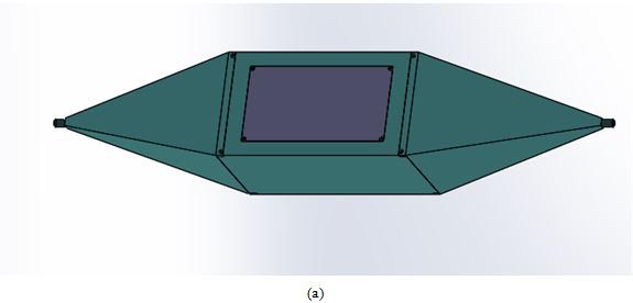
Figure 1: (a) 3D structure diagram of the device. (b) Side view dimensions of the device (mm). (c) Top view dimensions of the device (mm).
In this paper, a rectangular TEM device with wideband and sufficient space is proposed for cell experiments. The proposed rectangular device is capable of producing a uniform planar electromagnetic wave with wideband property in a limited enclosed space. In order to not only obtain more accurate measured results but also expand application range of the device in practical needs [11], the proposed rectangular TEM device is aiming to overcome the restrictions on available testing space. The rectangular TEM device proposed can operate at the frequency range from DC up to 5.2 GHz. And it forms a uniform TEM electromagnetic field in the radiation space, which can be used to detect cell electromagnetic properties in electromagnetic radiation experiments.
II. THEORY ANALYSIS OF THE PROPOSED DEVICE
The proposed structure is a coaxial cavity structure. The outer conductor is composed of a rectangular cavity in the middle and a square cone cavity on both sides, and the inner conductor is composed of a rectangular conductor plate in the middle and two trapezoidal conductor plates on both sides, as shown in Figure 1(a). The coaxial structure is a dual conductor guiding system, which consists of internal and external systems. It mainly transmits TEM wave. When there is discontinuity or high-frequency operation, it will excite TE mode or TM mode. The device has two coaxial ports at the ends of the cell. The external dimension of the proposed rectangular square cone coaxial cavity is 1176 mm 220 mm 220 mm, with coaxial connectors at both ends. The middle section of the inner conductor is a rectangular conductor plate with thickness of 8 mm and width of 131 mm, and the inner conductors on both sides are trapezoidal conductor plates with thickness of 8 mm and width from 131 mm gradually changing to 8 mm, as shown in Figures 1(b) and (c). When a certain frequency and power signal is added to the excitation port, the electromagnetic wave inside the device is excited in the form of TEM. In order to achieve uniform field distribution, the device adopts a symmetrical structure. The inner and outer conductors of the device are made of aluminum, the wall thickness of the outer conductor is 10 mm, and the dielectric supports are composed of two 10-mm-thick PTFE materials. The cell dish is placed in the middle of the radiation space.
One port of rectangular square cone coaxial cavity is connected with RF signal generator, and the other port is connected with 50- load to ensure good impedance matching. The calculation model of middle section of radiation device is illustrated in Figure 2. The cross-sectional size for the middle part of the inner conductor of the rectangular square cone coaxial cavity is obtained by the following formula [12]:
| (1) |
| (2) |
where C is the unit capacitance between inner and outer conductors, is the dielectric constant of media between inner and outer conductors, w is the cross-sectional width of inner conductor plate, t is the thickness of inner conductor, g is the distance from the inner conductor to the outer conductors on sides, and h is the distance from the inner conductor to the top or bottom outer conductors. At first, the values are calculated based on formulae (1) and (2). It is then further optimized in CST software.
The transition section design is mainly to make a good match between the input end of the cell and the power supply. The traditional transition section of TEM cell adopts stepped transition structure, which is generally circular coaxial and circular coaxial transition. Because of the step discontinuity of the structure, the transition structure will have a great reflection, which will affect the transmission and other performance of the TEM cell. In order to solve this problem, a new type of gradual transition structure is proposed, which is circular coaxial rectangular coaxial tapered structure. This structure has low reflection loss and can be used in cell electromagnetic radiation structure to improve transmission performance.
The input port of the transition section of the device is connected with the N-type coaxial RF connector, and the output port is connected with the rectangular coaxial cavity of the device. In order to make the working frequency of the device reach 5.2 GHz, the design of the transition section should ensure to meet the 50- characteristic impedance matching. It is also necessary to make sure that the cut-off frequency of the transition section should be greater than the working frequency and suppress the high-order noise when working in the high-frequency section [17, 18, 19, 20]. A slow gradual structure is adopted to minimize the discontinuity caused by the gradual transition [13, 14, 15, 16].
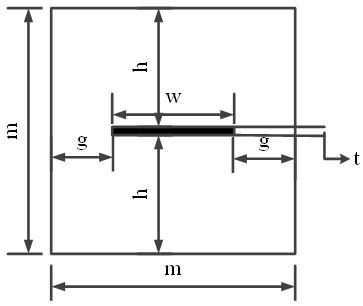
Figure 2: Calculation model of middle section of radiation device.
III. SIMULATION AND ANALYSIS
A. Simulation and optimization
The electromagnetic simulation for the rectangular square cone coaxial cavity is carried out with CST Microwave Studio Suite TM 2013. The impedance matching of the structure is mainly affected by the width w of the middle section of the inner conductor plate and the length H1 of the transition section; thus, the optimization and parameter scanning analysis of w and H1 is carried out. Figure 3 shows the structure diagram of identification H1. Figure 4 shows the S for different H1 and w. When other structural parameters of rectangular square cone coaxial cavity are fixed and H1 is changed, the curve of S is shown in Figure 4(a). It can be seen that the best H1 value is 36.5 cm, which makes S below 10 dB in the range of DC to 5.2 GHz. In the frequency range of 5.26 GHz, S is slightly higher than 10dB, which is caused by higher order modes. When w changes and other structural parameters are fixed, the curve of S is shown in Figure 4(b). It can be seen that the optimal w value is 13.1 cm, which makes S lower than 10dB in the DC to 5.2 GHz range. In the frequency range of 5.26 GHz, S is also slightly higher than 10dB. Due to the large size and wide frequency range of the structure, high-order modes will appear in the high-frequency band, and the influences of dielectric supports, which will have a certain impact on the transmission of electromagnetic waves, and the results of S will also fluctuateaccordingly.
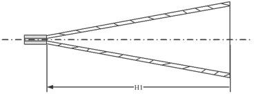
Figure 3: Structure diagram of identification H1.
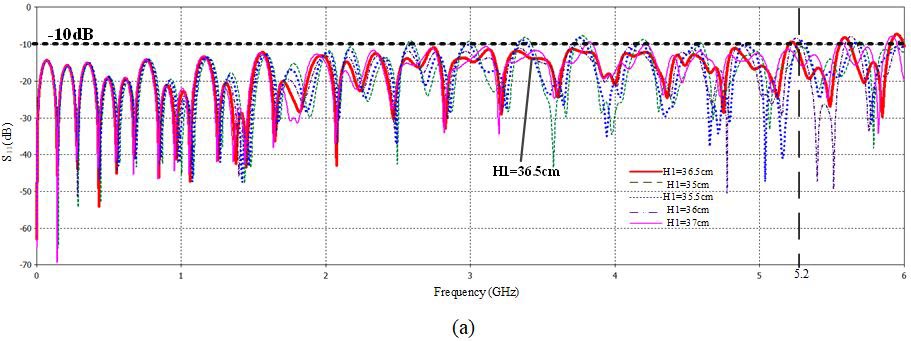
Figure 4: Simulated S versus frequency with (a) the length of the tapered transition H1 and (b) the width of the inner plate structure.
B. Experimental results and discussions
According to the optimization results, the rectangular square cone coaxial cavity is fabricated, and the experimental prototype is shown in Figure 5. It is tested with vector network analyzer AV3629B.
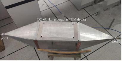
Figure 5: Photograph of the rectangular device.
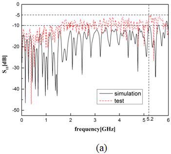
Figure 6: (a) The simulated and measured results of reflection coefficient S from DC to 6 GHz. (b) The simulated
and measured results of transmission coefficient S from DC to 6 GHz. (c) E-field distribution at Z = 0.
The simulated and measured results of the device are depicted in Figure 6. The reflection coefficient S is depicted in Figure 6(a) and the transmission coefficient S is depicted in Figure 6(b). It depicts that the S is better than 10 dB in the frequency range of DC to 5.2 GHz, S is nearly 0 dB in the frequency range of DC to 2 GHz, and Sis between 0 and 1 in the frequency range of 25.2 GHz. As can be seen from Figure 6(a), the matching bandwidth of a radiation system is typically defined by the frequency bandwidth where the reflection coefficient is lower than 10 dB. Note that some of the S values for the radiation device within its bandwidth are slightly greater than 10 dB. This is probably because there is little reflection at the junction of the transmission section and the joint of the rectangular device. And higher order modes occur at some high frequency, which will influence the transmission performance in reality. As can be seen from Figure 6(b), good consistency has been obtained between the simulations and measurements. Due to the machining error, measured results are slightly biased at individual frequencies. Both the simulated and measured results show that the device has a good transmission performance and impedance matching from DC to 5.2 GHz.
The distribution of E-fields at Z = 0 in the device is depicted in Figure 6(c). It can be seen that distribution of the electromagnetic field is mostly green, and the electric
field distributions are formed uniformly along the transverse plate. And we can conclude that there is a relatively uniform electromagnetic field inside the cavity. A uniform electromagnetic field is generated inside the outer conductor, and the outer conductor shell does not produce electromagnetic field. The uniform electric field distribution is essential for the radiation space and cell experiments.
Compared with the traditional TEM cells, simulated and measured results of this device show a good performance in the frequency range. And the device has advantages in sufficient radiation space and wide frequency band.
Table 1: Comparison between the proposed rectangular device and previously reported designs
| Ref. | Structure | Frequency range (GHz) | Size ( ) (mm) | S(dB) |
|---|---|---|---|---|
| [2] | Open TEM cell | 0.5 to 3 | 200 85 20 | Below 7.5 |
| [5] | TEM cell | 2.5 | 1700 120 120 | |
| [7] | Open TEM cell | DC to 1 | 200 100 30 | |
| [8] | TEM cell | 1.8 | 198.8 78 82 | |
| [9] | TEM cell | DC to 1 | 410 260 150 | Below 9 |
| [10] | Open TEM cell | DC to 3 | 202 85 20 | Below 10 |
| [11] | Twin TEM cells | 1 | 300 300 200 | |
| [13] | Cylindrical TEM cell | DC to 1 | 1021.2 150 150 | Below 13 |
| [14] | Two-port rectangular TEM cell | 0.53 | 444 364 360 | |
| [16] | TEM cell | DC to 3 | 280 150 90 | Below 15 |
| This work | Closed rectangular device | DC to 5.2 | 1176 220 220 | Below 10 |
IV. COMPARISON OF THE TRADITIONAL TEM DEVICES
Table 1 summarizes the performance comparison between the proposed rectangular device and previously reported designs for radiation experiments.
The proposed rectangular device shows the widest frequency range compared with other designs [5, 8, 11] for the radiation frequency range. In the item of structure, the proposed rectangular device is a closed Pdevice, which can eliminate electromagnetic leakage and play a shielding role compared with [2]. Compared with [9, 13, 15], the proposed rectangular device not only broadens the frequency range but also increases the radiation space. In general, the proposed rectangular device has obvious advantages in the sufficient radiation space and broadband aspect.
V. CONCLUSION
In this paper, a rectangular TEM device for cell experiments is proposed, which uses a rectangular coaxial structure as the radiation section. Its configuration is given, and the related key parameters are discussed. The measurements show that S is better than 10 dB in the frequency range of DC to 5.2 GHz, and S is nearly 0 dB which shows the proposed device can be used for the broadband cell radiation experiments. Compared with other designs, the overall performance of the proposed device is better. The proposed device successfully upgrades the frequency to a wideband range and expands the space for cell experiments. The proposed prototype is expected to have a very broad prospect in cell radiation experiments of the wide frequencyrange.
REFERENCES
[1] G. Shi, Y. Zhang, Y. Liao and X. Ying, “Characteristics of the electromagnetic radiation emission from coaxial cable of a type inverter,” 2015 IEEE 6th International Symposium on Microwave, Antenna, Propagation, and EMC Technologies (MAPE), Shanghai, pp. 458-461, 2015.
[2] M. Soueid, S. Kohler, L. Carr, S. M. Bardet, R. P. O’ Connor, P. Leveque, and D. A. Cormos, “Electromagnetic analysis of an aperture modified TEM cell including an ITO layer for real-time observation of biological cells exposed to microwaves”. Progress in Electromagnetics Research. vol. 149, pp. 193-204, 2014.
[3] S. Kohler, N. Ticaud, M. M. Iordache, M. G. Moisescu, T. Savopol, P. Leveque, and D. Arnaud-Cormos, “Setup for simultaneous microwave heating and real-time spectrofluorometric measurements in biological systems”. Progress in Electromagnetics Research. vol. 145, pp. 229-240,2014.
[4] C. Merla, N. Ticaud, D. Arnaud-Cormos, B. Veyret, and P. Leveque, “Real-time RF exposure setup based on a multiple electrode array (MEA) for electrophysiological recording of neuronal networks”. IEEE Transactions on Microwave Theory and Techniques. vol. 59, no. 3, pp. 755-762,2011.
[5] A. Paffi, M. Liberti, F. Fratta, F. Apollonio, C. Merla, R. Pinto, and G. Lovisolo, “A TEM cell system for in vivo exposure at 2.45 GHz”. In Proceeding of the 2012 6th European Conference on Antennas and Propagation (EUCAP), Prague, Czech Republic, pp. 1099-1101, 2012.
[6] M. L. Crawford, “Generation of standard EM fields using TEM transmission cells”. IEEE Transactions on Electromagnetic Compatibility, vol. 16, pp. 189-195, 1974.
[7] R. P. O’Connor, S. D. Madison, P. Leveque, H. L. Roderick, and M. D. Bootman, “Exposure to GSM RF fields does not affect calcium homeostasis in human endothelial cells, rat pheocromocytoma cells or rat hippocampal neurons”. Plos One. vol. 5, no. 7, pp. e11828, 2010.
[8] X. Z. Jian, H Lu, and J Deng, “Dosimetry and temperature evaluations of a1800 MHz TEM cell for in vitro exposure with standing waves”. Progress in Electromagnetics Research. vol. 124, pp. 487-510, 2012.
[9] C. Iftode and S. Miclaus, “Design and validation of a TEM cell used for radio frequency dosimetric studies”. Progress in Electromagnetics Research. vol. 132, pp. 369-388, 2012.
[10] S. Kohler, R.P. O’Connor, T.D.T. Vu, P. Leveque, and D. Arnaud-Cormos, “Experimental microdosimetry techniques for biological cells exposed to nanosecond pusled electric fields using microfluorimetry”. IEEE Transactions on Microwave Theory and Techniques. vol. 61, no. 5, pp. 2015-2022, 2013.
[11] C. Song and X. Feng, “A new design and implementation of expanding testing space of a transverse electromagnetic cell,” 2016 IEEE International Conference on Microwave and Millimeter Wave Technology (ICMMT), Beijing, pp. 967-969, 2016.
[12] Q. Huang, Research of gigahertz transverse electromagnetic cell[D]. School of Physical Electronics, 2013.
[13] M. Arezoomand, M. K. Meybodi and N. Noori, “Design of a TEM cell using both multi-step and piecewise linear tapering,” 2016 8th International Symposium on Telecommunications (IST), Tehran, pp. 571-574, 2016.
[14] P. Alotto, D. Desideri and A. Mashio, “Parametric analysis and optimization of the shape of the transitions of a two-port rectangular TEM cell”. In the Proceeding of the 2012 International Symposium on Electromagnetic Compatibility (EMC EUROPE), Rome, Italy, pp. 1-6, 2012.
[15] Q. Y. Guo, Q. C. Liang, D. H. Luo, and Q. G. Liu, “An electric field probe calibration based on TEM cell and evaluation of its uncertainty”. Journal of Guangdong University of Technology. vol. 33, pp. 19-25, 2016.
[16] S. H. Wen, J. L. Zhang, and Y. H. Lv, “The optimization design of septum in TEM cells for IC EMC Measurement”. In the Proceeding of the 2015 7th Asia-Pacific Conference on Environmental Electromagnetics (CEEM), Hangzhou, China, pp. 250-253, 2015.
[17] S. B. Deng, D. Pommerenke, B. T. Hu and D. Shin, “An experimental investigation of higher order mode suppression in TEM cells,” IEEE Transactions on Electromagnetic Compatibility, vol. 50, no. 2, pp. 416-419, 2008.
[18] V. Chechetkin, A. Korotkov, E. Golubenko, E. Sychugov and P. Smirnov, “Investigation of the characteristics of the TEM cell model,” 2019 Ural Symposium on Biomedical Engineering, Radioelectronics and Information Technology (USBEREIT), pp. 439-441,2019.
[19] X. M. Wang, X. K. Kong, S. L. Jiang, L. Q. Kong, W. H. Lin and B. R. Bian, “A wideband open TEM cell to measure the frequency response of a frequency selective surface,” 2020 IEEE 3rd International Conference on Electronic, pp. 321-323, 2020.
[20] M. Mierka, “Realization of a TEM cell,” 2019 12th International Conference on Measurement, pp. 162-166, 2019.
BIOGRAPHIES

Shiqi Wang was born in Shenyang, China. She received the B.Eng. and M.Eng. degrees in information and communication engineering from Dalian Maritime University, Liaoning, China, in 2014 and 2017, respectively. She is currently working toward the Ph.D. degree with the Dalian Maritime University.
Her current research interests include wideband electromagnetic field, bioelectromagnetics, and optimizationmethod.

Shaojun Fang received the Ph.D. degree in communication and information systems from Dalian Maritime University (DLMU), Liaoning, China, in 2001.
Since 1982, he has been with DLMU, where he is currently the Head Professor with the School of Information Science and Technology. His recent research interests include passive RF components, patch antennas, and computational electromagnetics. He has authored or coauthored three books and over 100 journal and conference papers.
Dr. Fang was a recipient of the Best Doctor’s Dissertation Award of Liaoning Province in 2002 and the Outstanding Teacher Award of the Ministry of Transport of China.
Peng Chen received the Ph.D. degree in communication and information systems from Dalian Maritime University (DLMU), Liaoning, China, in 2007.
He is currently an Associate Professor with the School of Information Science and Technology, DLMU. His current research interests include wireless sensor network, ultra-broadband wireless communication technology, and antenna.
ACES JOURNAL, Vol. 37, No. 1, 85–92.
doi: 10.13052/2022.ACES.J.370110
© 2021 River Publishers