Simulation of High Frequency Twisted Pair Cable Using DDM-FEM Hybrid Algorithm
S. Khan, Y. Zhao, Y. Wei, A. Mueed, Z. Ullah, and A. Khan
Department of Electrical and Automation Engineering, Nanjing Normal University, Nanjing 210046, China
engrshumail456@yahoo.com, zhaoyang2@njnu.edu.cn, 61197@njnu.edu.cn, engr.mueed@live.com, engrzakirullah@yahoo.com, Abubakarkhan92064@gmail.com
Corresponding author from Nanjing Normal University, Nanjing, China.
Submitted On: July 27, 2021; Accepted On: October 18, 2021
Abstract
In this article, an efficient domain decomposition method finite element method (DDM-FEM) algorithm is presented for the lossy twisted pair cable. In harsh environment and anti-interface ability, cables need high toughness, noise immunity, and extraordinary strength. We, in this paper, simulate a physical model of twisted pair cable and apply a hybrid solver of DDM-FEM to analyze these problems by compression and approximation of matrix-vector product. The DDM-FEM solver along with matrix compression is used to compute the RLCG, propagation constant in the twisted pair cable, and to reduce the computational time and memory size. Therefore, in the proposed algorithm, the complexities of the system become linear. The study compares the calculated results with the existing standard to verify the effectiveness of the proposed algorithm.
Keywords: Domain decomposition method (DDM), finite element method (FEM), hybrid solver, propagation constant, RLCG parameter, twisted pair cable.
I. INTRODUCTION
With the advancement of technology, means of data and information transfer is improving day by day. To ensure maximum and reliable data, communication signals need a secure way to transfer data with minimum interface. This can be achieved through twisted pair cable, coaxial cable, and optical fiber cable, which are developed to bear higher frequency signal with minimum interface.
Twisted pair cable has been used for a long time due to its high toughness, good noise immunity, and high strength. Twisted pair cables are usually used in harsh environment due to robustness and anti-interface ability to conduct noise. Over the years, twisted pair cables have been used with different frequencies ranging from 16 MHz to 1.8 GHz [1, 2, 3]. Our focus in this paper is to further increase the frequency to 5 GHz in shielded category of twisted pair cables, which will reduce propagation loss. To evaluate the performance, we analyze the primary (electrical) and secondary parameters in this paper. Resistance (R), inductance (L), capacitance (C), and conductance (G) matrices give the electrical parameters. Similarly, secondary parameters are propagation constant (), attenuation constant (), phase constant (), characteristic impedance (), scattering parameter (s) and permeability constant of free space Epsilon () [4, 5, 6, 7].
To compute the electrical and secondary parameter of twisted pair cable, different numerical techniques are used such as method moment [8], frequency domain and time domain (FDTD) techniques [9, 10], advanced modeling (AM) techniques [11], domain decomposition method (DDM) [12], and traditional finite element method (FEM) approach [13].
Among the above-mentioned techniques, the DDM decomposes the domain into subdomains and then create a mesh to solve each of these subdomains separately. On the other hand, FEM uses triangular mesh method to solve inhomogeneous structure effectively and efficiently. We thus combine the two methods (FEM and DDM) to first divide given structure subdomains and then apply FEM method to solve for each subdomain. This way, we exploit the advantages of both the methods to reduce the propagation loss.
Parallel computing system requires a much smaller amount of computation memory than the conventional FEM for structure, which is bent or twisted. DDM represents a large potential for parallelization of the FEMs. It also serves as a basis for distributed, parallel computations with high performance (over 90%) which is achieved even in a large-scale finite element calculation with irregular domain decomposition [14, 15].
This article is structured as follows. In Section II, the mathematical equations of twisted pair cable performance parameters are described. In Sections III and IV, DDM and FEM implementation are described, respectively. In Section V, numerical simulation using proposed algorithm and validation result are presented. Finally, Section VI concludes the work.
II. SHIELDED TWISTED PAIR CABLE
Shielded twisted pair (STP) cable is a type of guided transmission medium, which consists of individual pair of wires, each having two conductor wires twisted together in a regular spiral pattern. Individual pair or collection of pair are shielded with foil or braided wire to reduce the electromagnetic (EM) interference. The shield further connects to ground reference, which protects the induced current to wire and attenuates the EM wave for external shielding. The propagation matrix () for the STP cable is given as
| (1) |
where is the attenuation constant and is the phase constant and both are in matrix form. We can also write it as
| (2) |
where = 2 and R, L, C, and G are the electrical parameter of twisted pair (STP) cable and are given as
| (3) |
| (4) |
| (5) |
| (6) |
where D is the distance between the center of two conductor cables for multi-twist, d is the diameter of each conductor, and is the surface resistance of conductor and is given as (), where is constant and its value is 2.16 . Here, is the conductivity of the conductor material, and is skin depth. The conductivity of the dielectric can be given as (). The other constants are: = 2/, = 2 , and = 8.85 .
Comparing eqn (1) and (2) of propagation constant, we can find the attenuation and phase constant, where the real part is attenuation and the imaginary part is phase constant described as
| (7) |
If t is the thickness of the dielectric, then the ratio of and the attenuation constant in dB is given as
| (8) |
where
| (9) |
and
| (10) |
Eqn (8) will become
| (11) |
From the imaginary part of eqn (2), phase constant of the cable can be found as
| (12) |
Let us assume
| (13) |
and
| (14) |
Hence, eqn (12) will become
| (15) |
A. Propagation constant of STP cable
STP cable propagation constant can be found by putting the value of eqn (11) and (15) in eqn (1), resulting in the propagation constant as
| (16) |
III. DOMAIN DECOMPOSITION METHOD
DDM is applied to solve, which solves the boundary value problem (BVP) by decomposing the domain to subdomain. The domain contains the information about the proposed model. Each domain has different configuration of material as well as geometry. The subdomains are further divided which make the partitions even smaller. These subdomains are easily solvable by the DDM. The domain contains the information locally; so it is convenient to solve the performance parameters. As they accelerate the solution to convergence point. Due to the locally connected domain, the performance parameters are calculated speedily. It also decreases the memory size and CPU time.
If we consider decomposition on the domain of S belong to (), S is decomposed into two subdomains . The subdomains have different material properties than domain S. Excitation of the problem may be discreet or fast or both of them.
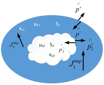
Figure 1: Domain S with boundary value problem.
In this manuscript, the grid-based approach for matching algorithms of DDM. The grid-based approach is used for defining the subdomain. A domain is divided into subdomains and artificial boundaries known as “interface”. It means that each subdomain is independently solved. To get proper solution, the appropriate boundary condition must be given on the interface of subdomains. The DDM based on natural boundary conditions reduces the approximation under the matching condition. We use the grid-based approach for matching purpose. To obtain the accuracy of the solution, it is necessary to use high refinements of the finite element grids near the concave vertices. So the solution is improved by using the grid approach near the concave vertex. Therefore, the solution offers good approximation by using the grid matching approach.
As shown in Figure 1, the domain S is divided into subdomains . The shape of subdomain has the same geometrical shape as that of domain S, but the shape of subdomain has a different geometrical shape from domain S, having no geometrical information.
The same material as is meshed in subdomains and separately. The surface subdomain, initially decomposed BVPs are without connection between them. Moreover, for subdomain is given as follows:
| (17) | |
For
| (18) | |
Intrinsic impedance for free space, are the relative permittivity and permeability of material in , express the relative wave impedance, . Moreover, the tangential element trace operator and twist tangential trace operator are adopted in our analysis, defined as
| (19) |
| (20) |
where and are the unit outward and inward normal to domain and subdomain , respectively. refers to the field jump across a surface
| (21) |
In eqn (18), expresses the collection of PEC surface where the tangential component of electric field finishes. expresses the surface of internal port on which a specific current density exists. If is the proper space , the normal curl conforming function space is
| (22) |
Contribute to the progress of the volume and surface time product as and , respectively.
The information sent and received are between the subdomains It includes transfer of information or data in two directions, i.e., from to and from to .
A. Coupling from to
As is the field continuity between subdomains and , it will be observed and applied through the Robin transmission condition on as
| (23) | |
Here, the
As the expresses the auxiliary variable, the surface electric current on, so
As and obtained below as
| (24) |
B. Coupling from to
Transmission of information from to requires polarization of subdomain , which will also depict the material difference, and the use of surface domain current to justify surface subdomain. This embedded subdomain contains the data of material properties.
C. Material difference
As for the solution of BVP surface subdomain , and are the electric and magnetic fields. We apply and into the Maxwell equation of surface subdomain as
| (25) |
| (26) |
The above two equations (25) and (26) are the electric and magnetic polarizations due to change of material properties from , to ,. Moreover, subdomain surface and vector wave equation are improved by combining eqn (25) and (26) as
| (27) | |
and are two volume sources as
| (28) |
| (29) |
Eqn (27) with;so
| (30) | |
Therefore, at the (1)th iteration, we make and based on the simulation result of surface subdomain . This will be applied on subdivided surface subdomain for the local FEM simulation at the iteration.
IV. FINITE ELEMENT METHOD IMPLEMENTATION
As discussed in Section III.B.I, full discrete embedded system DDM will make matrix equation by applying Galerkin testings as
| (31) |
Here, is the solution vector coefficient of the basic functions in , and is the excitation vector. and are the block matrices that stand for the FEM matrices of subdivided surfaces’ area and . and are off-diagonal matrices used as coupling between subdivided surface areas and .
Here, we will use to mesh triangular/tetrahedral the subdivided surface area.
However, the Gaussian quadrature integration is used to solve discrete system in eqn (31). Gaussian Seidel matrix symmetric block is used for preconditioner system as
| (32) |
| (33) |
Preconditioner needs inversion of subdivided matrices and. By using the multifrontal solution process [16, 17], we can factorize the subdomain matrices.
Moreover, embedded DDM has many advantages; it can discretize one domain into subdomains. Therefore, we can make embedded mesh of complicated geometries by dividing them into too many small subdomains, from which we get good quality of mesh. The small subdomain meshes and matrix assembly are independent. Therefore, if we want to move subdivided area with respect to , only the matrices and in eqn (31) need to be re-calculated. As DDM subdomain needs to be recomputed by modifying or adding other subdomains. This will help us in EM modeling, designing, and in solving practical problems.
V. NUMERICAL SIMULATION USING PROPOSED ALGORITHM
In this section, we discuss numerical simulations of shield twisted pair cable to evaluate the electrical parameter (RLCG) and secondary parameter (propagation constant). Therefore, the shield multi-twisted pair cable(s) are chosen for research work. The shield twisted pair conductors are composed of seven pairs cable model as shown in Figure 2.
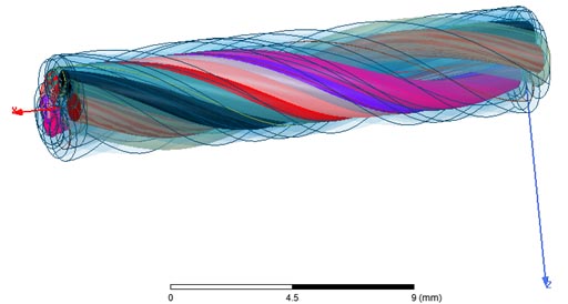
Figure 2: Study model of twisted pair cables.
In overlapping DDMs, the subdomains overlap by more than one interface. Overlapping DDMs include the Schwarz alternating method and the additive Schwarz method.
The simulation frequency is 5 GHz, and the step size is 451. The convergence criteria of maximum delta are 0.02, and the number of passes for the convergence of solution is 10.
A. RLCG constant based on DDM-FEM algorithm
In this section, comparison among different methods regarding efficiency and strength of proposed algorithm is checked. Here, all simulation results are taken from ANSYS EM environment and MATLAB. The suggested method is used to determine the twisted cable effect in the test example. All the conductors are discretized into triangular and tetrahedral structure with refined mesh. The matrix is reduced up to 1:29%, by the DDM-FEM. The minimum residuals for the tolerance are .
Using the proposed algorithm, the twisted pair level effect and multi-layer effect are estimated. The DDM-FEM algorithm is suitable for calculating the RLCG parameter using different iterations. Based on the result, mutual capacitance and mutual inductance are calculated by the DDM-FEM approach. The mutual capacitance and inductance (impedance) are shown in Figures 5 and 6.
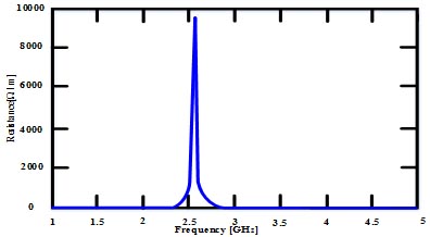
Figure 3: Resistance of twisted pair.
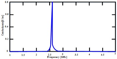
Figure 4: Conductance of twisted pair.
Initially, the resistance is zero at 12.5 GHz, but as the frequency increases from 2.5 GHz, the resistance also increases. It shoots up to 1000 /m and becomes 0 /m again at 2.7 GHz. Moreover, as it is shown in Figure 3 that further increase in the frequency up to 5 GHz is not showing any deviation in the resistance. In addition, this is same for conductance as well as shown in Figure 4.
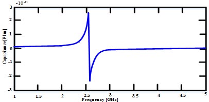
Figure 5: Capacitance of twisted pair.
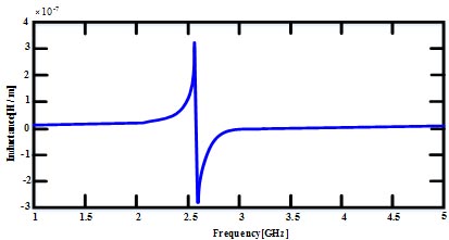
Figure 6: Inductance of twisted pair cable.
As shown in Figures 5 and 6, the shape of the graph is almost same for inductance and capacitance. Initially, at zero frequency, we have some residual inductance and capacitance, but as the frequency increases up to 2.3 GHz, its values gradually increase and reach its peak of inductance and capacitance value and then abruptly decrease the inductance to 3 H/m and capacitance 2.9 F/m at frequency of 2.6 GHz. As the frequency increases more, the inductance and capacitance also increase and reach up to inductance and capacitance of 1.5 H/m and 1.5 F/m.
At 3 GHz up to 5 GHz, the inductance and capacitance are at steady state.
B. Propagation constant based on hybrid algorithm
In this subsection, the propagation matrix and attenuation matrix of the twisted pair cable are estimated. The characteristic parameters of twisted pair model are shown in Table 1.
Table 1: Characteristics of twisted pair
| Radius | 0.28 |
|---|---|
| No of twisted (under test) | 1 |
| Total number of twisted pair | 7 |
| Material | Copper |
| Dielectric | Polyester |
| No of adaptive passes | 10 |
| Frequency | 5 GHz |
Table 2: Computational memory of twisted pair cable
| No of unknown | Memory (MBs) | No of adaptive passes |
|---|---|---|
| 349,722 | 30.103 | 1 |
| 428,992 | 32.337 | 2 |
| 428,992 | 31.200 | 3 |
| 545,330 | 42.343 | 4 |
Table 3: Computational time of twisted pair cable
| No of unknown | CPU time (matrix assembly) | No. of adaptive passes |
|---|---|---|
| 349,722 | 00:00:06 | 1 |
| 428,992 | 00:00:08 | 2 |
| 428,992 | 00:00:08 | 3 |
| 545,330 | 00:00:10 | 4 |
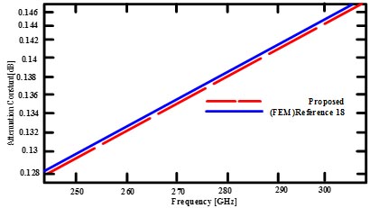
Figure 7: Attenuation constant of twisted pair cable.
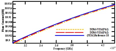
Figure 8: Phase constant of twisted pair cable.
Table 1 describes the model of twisted pair cable. The number of adaptive passes and significant value of delta can be adjusted for the convergence of solution. Table 2 and 3 describe the memory and time computation of twisted pair cable. This information gives the real and imaginary values to analyze the propagation constant and attenuation constant using FEM-DDM. To verify the algorithm result, comparison takes place with the numerical analysis techniques using FEM [18]. ANSYS environment models and compared the result. Figure 7 shows the comparison of propagation loss. The X-axis represents the propagation loss and Y-axis represents the frequency in GHz and normalized values. Figure 8 shows the simulation of phase constant. Here, FEM-DDM results are adequate with respect to FEM results as shown in Figures 7 and 8.
VI. CONCLUSION
In this article, the DDM-FEM algorithm calculates the RLCG parameters and propagation loss of STP cable. The versatile nature of FEM with integral equation solver gives good approximation of RLCG matrix and propagation matrix. The computing efficiency parameter of the STP cable is estimated through the DDM-FEM algorithm and offers less computational time and memory than the traditional method. The approximation is 1:85% than matrix transmission line theory.
ACKNOWLEDGMENT
National Natural Science Foundation of China under Grant 52107005 and “Open Fund Project of State Key Laboratory of Power Grid Environmental Protection (GYW51202001558)” supported the paper.
REFERENCES
[1] S. Abdolhamid, M. Rubinstein, A. Rubinstein, C. Romero, N. Mora, and F. Rachidi, “Application of the cascaded transmission line theory of Paul and McKnight to the evaluation of NEXT and FEXT in twisted wire pair bundles,” IEEE transactions on electromagnetic compatibility, vol. 55, no. 4, pp. 648-656, 2013.
[2] A. Mueed, Y. Zhao, Y. Wei, Z. B. Zhu, and Q. L. Liu, “Analysis of lossy multiconductor transmission lines (MTL) using adaptive cross approximation (ACA),” Applied Computational Electromagnetics Society Journal, vol. 34, no. 11, 2019.
[3] H. Ali Mohajer, G.-J. Stockman, Y. Lefevre, V. Ginis, and W. Coomans, “Calculating millimeter-wave modes of copper twisted-pair cables using transformation optics,” IEEE Access, vol. 9, pp. 52079-52088, 2021.
[4] A. Mueed, Y. Zhao, W. Yan, S. Khan, Q. Q. Liu, and C. Huang, “Skin effect and proximity effect analysis of stranded conductor based on mixed order MoM with adaptive cross approximation algorithm,” Engineering Analysis with Boundary Elements, vol. 120, pp. 52-58, 2020.
[5] J. E. Schutt-Ainé, “High-frequency characterization of twisted-pair cables,” IEEE Transactions on Communications, vol. 49, no. 4, pp. 598-601, 2001.
[6] M. Yamamura, Y. Kami, K. Murano, and F. Xiao, “Analysis of transmission characteristics for twisted pair cables using the RLGC parameters of the cable,” Asia-Pacific Symposium on Electromagnetic Compatibility (APEMC), Taipei, pp. 720-723, 2015.
[7] C. Yang, W. Yan, Y. Zhao, Y. Chen, C. Zhu, and Z. Zhu, “Analysis on RLCG parameter matrix extraction for multi-core twisted cable based on back propagation neural network algorithm,” in IEEE Access, vol. 7, pp. 126315-126322, 2019.
[8] D.A. Weston, Electromagnetic Compatibility: Methods, Analysis, Circuits, and Measurement, Third Edition (3rd ed.). Crc Press. 2016.
[9] Y. Yan, L. Meng, X. Liu, T. Jiang, J. Chen, and G. Zhang, “An FDTD method for the transient terminal response of twisted-wire pairs illuminated by an external electromagnetic field,” in IEEE Transactions on Electromagnetic Compatibility, vol. 60, no. 2, pp. 435-443, Apr. 2018.
[10] Q. Q. Liu, Y. Zhao, C. Huang, W. Yan, and J. M. Zhou, “A new method for stranded cable crosstalk estimation based on BAS-BP neural network algorithm combined with FDTD method,” Applied Computational Electromagnetics Society Journal, vol. 35, no. 2, Feb. 2020.
[11] C. Jullien, P. Besnier, M. Dunand, and I. Junqua, “Advanced modeling of crosstalk between an unshielded twisted pair cable and an unshielded wire above a ground plane,” in IEEE Transactions on Electromagnetic Compatibility, vol. 55, no. 1, pp. 183-194, Feb. 2013.
[12] I. Hänninen, F. Wolfheimer, A. Barchanski, and D. Kostka, “High performance computing techniques for efficient 3D full-wave simulation of EMC problems,” International Symposium on Electromagnetic Compatibility, Tokyo, Tokyo, pp. 828-831, 2014.
[13] C. Buccella, M. Feliziani, and G. Manzi, “Three-dimensional FEM approach to model twisted wire pair cables,” in IEEE Transactions on Magnetics, vol. 43, no. 4, pp. 1373-1376, Apr. 2007.
[14] A. Amor-Martin, L. E. Garcia-Castillo, and J. F. Lee, “Study of accuracy of a non-conformal finite element domain decomposition method,” Journal of Computational Physics, vol. 429, p. 109989, Mar. 2021.
[15] S. Yizhong, W. Sun, and H. Zheng, “Domain decomposition method for the fully-mixed Stokes–Darcy coupled problem,” Computer Methods in Applied Mechanics and Engineering, vol. 374, p. 113578, Feb. 2021.
[16] E. Lundquist, S. Wu, C. Furse, and B. Jones. “Aging wire fault diagnosis using faster, higher-precision methods,” In The 2011 Aircraft Airworthiness and Sustainment Conference, 2011.
[17] P. R. Amestoy, I. S. Duff, J.-Y. L’Excellent, and J. Koster, “A fully asynchronous multifrontal solver using distributed dynamic scheduling,” SIAM Journal on Matrix Analysis and Applications, vol. 23, no. 1, pp. 15-41, 2001.
[18] M. M. Al-Asadi, A. P. Duffy, K. G. Hodge, and A. J. Willis, “Twisted pair cable design analysis and simulation,” In 49th IWCS conference, Atlantic City, NJ, USA, pp. 13-16. 2000.
BIOGRAPHIES
Shumail Khan received the B.E. degree from CECOS University, Peshawar, Pakistan, in 2005-2010 and the master’s degree from Southeast University, Nanjing China, in 2015-2017.
He then worked as an Assistant Plant Engineer with Hydral Power station Malkand-III, his Dargi Pakistan in 2011-2015. He is currently a Ph.D. Research Scholar with Nanjing Normal University, Nanjing, China, under the supervision of Prof. Zhao Yang. His research interests include electromagnetic compatibility problems, computational electromagnetics, transient analysis, and crosstalk issues.

Zhao Yang received the B.E., M.E., and Ph.D. degrees in power electronic technology from the Nanjing University of Aeronautics and Astronautics, Nanjing, China, in 1989, 1992, and 1995, respectively.
He is currently a Professor with Nanjing Normal University, Nanjing, China. His research interests are in the areas of electromagnetic compatibility, power electronics, and automotive electronics.
Yan Wei received the M.S. degree in electrical engineering and the Ph.D. degree in physics and electronics from Nanjing Normal University, Nanjing, China, in 2011 and 2014, respectively.
Since 2014, he has been with the Jiangsu Electrical Equipment EMC Engineering Laboratory, Nanjing Normal University, where he is presently working as an Associate Professor. His current research interests include integrated circuit electromagnetic compatibility testing, bio-electromagnetic technology, and automotive electromagnetic compatibility design.

Abdul Mueed received the master’s degree in electrical engineering from the University of Engineering and Technology, Taxila, Pakistan, in 2015.
From 2009 to 2017, he worked as a Lecturer in Electrical Engineering with the Dr A Q Khan Institute of Technology, Mianwali, Pakistan. He is currently working as a Research Scholar with Nanjing Normal University, Nanjing, China. His primary research interests include the electromagnetic compatibility problems, computational electromagnetic techniques, artificial intelligence application in EMC, and EMC-related issues in biomedical.
ACES JOURNAL, Vol. 37, No. 1, 109–116.
doi: 10.13052/2022.ACES.J.370113
© 2021 River Publishers