Study of the Combination Method and Its Application to Shrink a Patch Antenna Operating in the UHF Band
Qianling Huang, Xiaofei Xu, and Ruiheng Zhang
1School of Communication and Information Engineering, Shanghai University, Shanghai 200444, China
2Key Laboratory of Specialty Fiber Optics and Optical Access Networks, Shanghai Institute for Advanced Communication and Data Science, Shanghai University, Shanghai 200444, China
xfxu@shu.edu.cn
Submitted On: November 9, 2021; Accepted On: March 16, 2022
Abstract
This work is focused on how to efficiently shrink a patch antenna operating in the UHF band. Five typical independent methods are first introduced that were solely used to realize a small patch antenna. A potential combination method is further discussed utilizing two or more of these five methods. One miniature patch antenna is experimentally demonstrated operating at 735 MHz using the combination method, in which both of shorting wall and complementary split ring resonators are applied in a reconciling way. A two-step optimization procedure is given to show how the antenna sizes can be significantly reduced with this combination method. The antenna is fabricated on a simple dielectric with a low of 2.2. The patch size is only 0.127 0.123. The antenna efficiency is considerably high as 77% in measurement.
Keywords: Combination method, patch antenna, small-sized, UHF band.
I. INTRODUCTION
Patch antennas are widely used in several gigahertz (GHz) range. Due to the resonance condition, the patch length is generally at the order of half guided wavelength (0.5) [1, 2]. The patch length is, however, physically large for an antenna operating below 1 GHz in the UHF band due to the long wavelength. In this work, we aim to shrink a patch antenna in the UHF band. We notice that a variety of miniaturization methods have been reported [3] to realize a compact patch antenna including: (I) shorting/folding technique [4–7]; (II) etching slots on the patch and/or ground planes [8–10]; (III) using natural magneto-dielectric with a higher relative permittivity and/or permeability [11–14]; (IV) using planar metamaterials [15–18]; (V) bulky metamaterials with effective permittivity , and/or permeability [19–26], etc. Most of them were nevertheless solely used.
Inspired by these technologies, a combination method by incorporating two or more of the five methods can be utilized to reduce the antenna size as well. The combination method is more effective than a single technique used on its own. Here, with the technologies of shorting wall and planar metamaterial structures, a combination method is demonstrated to significantly compact a patch antenna operating in the UHF band. The size reduction effect is numerically examined in a two-step optimization procedure. The first step is to add a shorting wall that makes the half-wave patch reduced to quarter-wave. The second step is to further shorten the quarter-wave length by loading periodic complementary split ring resonators (CSRRs) [16, 17, 27] on the patch. One shorted patch antenna with 2 2 CSRRs is experimentally studied resonating at 735 MHz. The patch antenna is fabricated on a simple dielectric with a low of 2.2. The patch size is only 0.127 0.123 ( is free space wavelength). The measured efficiency is 77%, which is in good agreement with the simulated value. The small shorted metamaterial patch antenna can be applied in the UHF band communications.
II. CONCEPT OF THE COMBINATION METHOD
The typical five methods to shrink patch antennas are given in Table 1. The five size multipliers from M to M are also given, which are used to measure how the antenna length is reduced from the original half-wave. Note that the first three methods [3–14] have been widely used in previous decades. The latter two methods [15–26] are, however, using new conceptual metamaterials. According to the metamaterial structures, they are further differentiated into planar and bulky types. The planar metamaterials are 2D structures [15–18], e.g., CSRRs, loaded on the patch or ground plane, which are similar with etched slots on the planes since they both need metal planes to make functional patterns. Hence, the second and fourth methods are sometimes incompatible. The bulky metamaterials are, however, 3D structures embedded in the dielectric substrate [19–26]. They are physically inhomogeneous included with composite subwavelength structures but work as homogeneous natural materials as if and .
Table 1: Five typical methods to shrink a patch antenna and the associated multipliers
| I | Shorting/folding technique | |
| II | Slotted patch/ground | |
| III | Natural magneto-dielectric (,) | |
| IV | Planar metamaterials | |
| V | Bulky metamaterials (,) |
Considering a conventional patch antenna with length L fabricated on a low loss nonmagnetic substrate with dielectric constant , the resonant frequency f is predicted using a simple formula [1, 2]
| (1) |
where c is the light speed in free space. Note that the margin effects are not accounted in eqn (1) for simplicity. The associated electric patch length is calculated as
| (2) |
From eqn (2), we see that the electric patch length is proportional to f. Hence, for a given L, the key issue to compact the antenna is to downshift f with the five methods listed in Table 1.
We now discuss the multipliers for these methods. On the basis of the conventional antenna discussed above, if the antenna size is kept unchanged when using these compacting methods, it will resonate at a new but lower frequency . Therefore, multiplier is approximately equal to , which is smaller than 1. For the first method of the shorting/folding technique, the multiplier is , where n is an integer. If only a shorting wall is added to the antenna [4–6], the half-wave antenna evolves to quarter-wave, e.g., n = 1 in this case. For more complex folding techniques[7], n can be 2, 3, or even larger.
The multipliers for the second method of adding slots on the patch or ground, and for the fourth method are both highly dependent on the shape and parameters of functional structures. Therefore, it will be difficult to given empirical solutions for M and M.
For the third method when the patch antenna is loaded with a natural magneto-dielectric with and , the resonant frequency becomes
| (3) |
The associated multiplier is M [/()]. The case for the fifth method is similar with eqn (3) but using effective and , which is
| (4) |
The associated multiplier is M [/()].
By incorporating all the five methods, we obtain
| (5) |
The new resonant frequency f in eqn (5) is now the product of f multiplied by a new size reduction operator M, which represents the total effect of the five methods. Considering the second and fourth methods are sometimes incompatible in a practical antenna design, we use a square bracket including these two multipliers, in which only one multiplier can be chosen for the same time. The case is similar for the second square bracket where the third and fifth methods are included. If the size reduction effects vary with frequency, these multipliers should be dispersive as well that only the effects around f need to be taken into account.
By utilizing the five methods in a combining way, the antenna length can be reduced more significantly than only one method used solely. In the following parts, one compact patch antenna will be demonstrated by incorporating two methods, in which both of a shorting wall and planar metamaterial structures are utilized.
III. ANTENNA DESIGN
A. Step 1: From half-wave to quarter-wave
We start from a conventional rectangular patch antenna. The prototype of the conventional antenna is given in Figure 1 (a) with patch size of L W and ground plane length G. In the side view of Figure 1 (b), we see that dielectric substrate is with thickness h, dielectric constant , and loss tangent tan. The patch and ground planes are both made of copper with conductivity of 5.8 10S/m and thickness t. The shorted patch antenna is shown in Figure 1 (c). A shorting wall composed of numerous conducting vias is added at the end of the shorted antenna. The shorting wall connects the patch and ground planes, making the half-wave patch length (~/2) reduced to quarter-wave (~/4). Note that the sizes for both antennas are identical. And they are both coaxially fed with characteristic impedance of 50 .
Assuming L = 52 mm, W = 50 mm, G = 100 mm, h = 12 mm, t = 0.035 mm, = 2.2, and tan = 0.001, we obtain the reflection coefficients (S11s) for the conventional and shorted patch antennas in Figure 2, using the numerical HFSS solver.
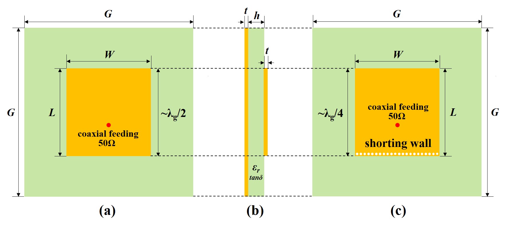
Figure 1: Antenna prototypes. (a) Top view. (b) Side view of a conventional patch antenna. (c) Top view of a shorted patch antenna.
It is seen that the resonant frequency is 1.788 GHz for the conventional antenna and 0.885 GHz for the shorted one. The patch lengths are 0.46 and 0.23 , respectively. If the margin effects for the patches are accounted, the lengths should be better near /2and /4.
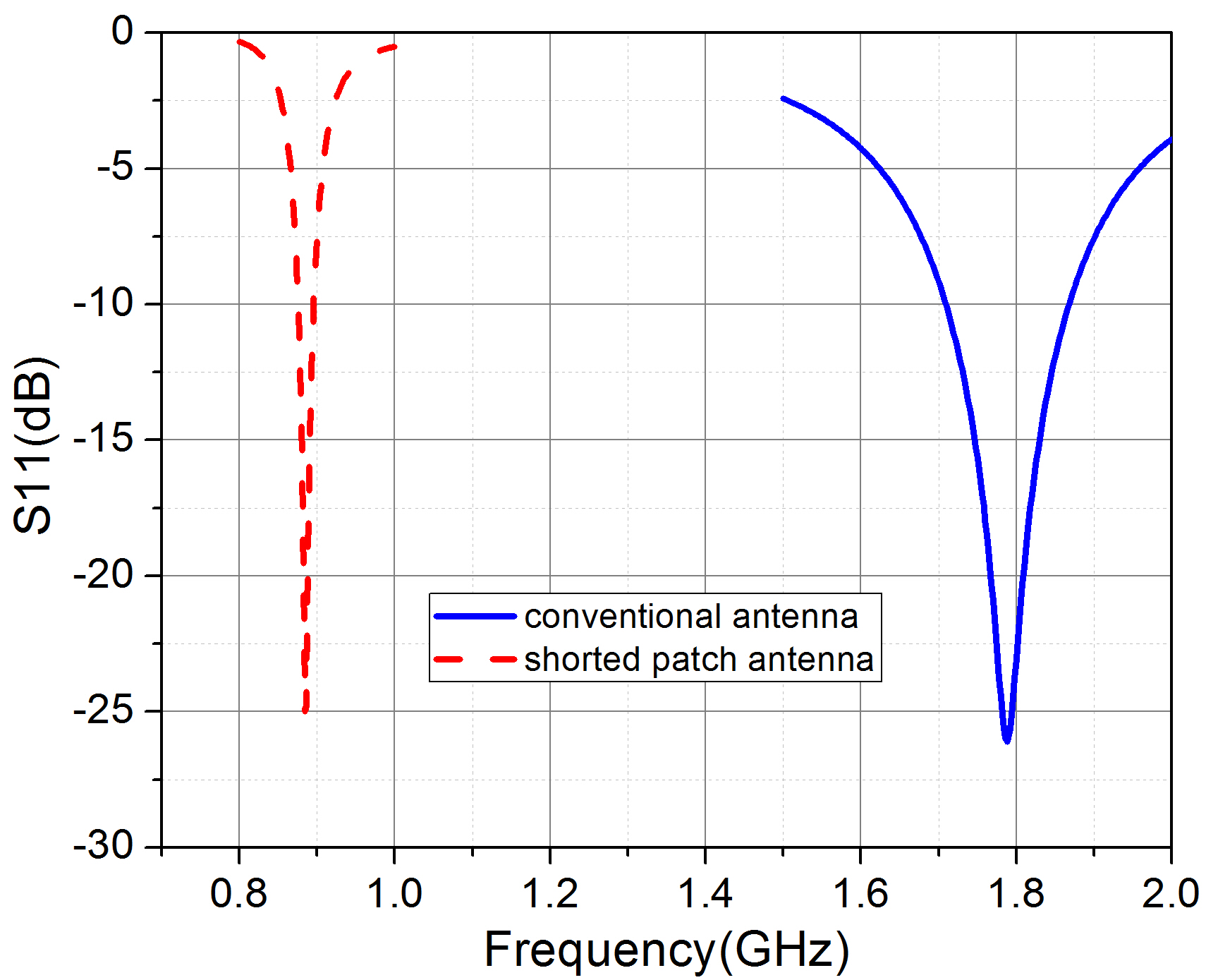
Figure 2: The simulated S11s for the conventional and shorted patch antennas.
B. Step 2: Beyond quarter-wave
To make the antenna smaller, the planar CSRRs are further added on the shorted patch. The scheme for one CSRR element is given in Figure 3 (a). They are excited by the electric fields perpendicular to the structures [16, 17], working as electric metamaterials. The mechanisms for the CSRRs can be explained using a lumped-element model (see Figure 13 in [27]) that the effective capacitance for the CSRR patch is increased than the original integrated one. The period for the CSRR element is p. Two slots are etched on the square structure. The length of the outer slot is a, while the width is g. These parameters can be tuned and adapted for different antenna applications. An array including CSRRs is designed on the patch, as shown in Figure 3 (b). The metamaterial antenna size is kept the same as the aforementioned one without CSRRs.
The geometry parameters for the CSRR structure are: p = 25 mm, a = 20 mm, g = 1 mm, d = 0.5 mm, and b = 2.5 mm. The shorted antennas loaded with CSRRs are subsequently calculated in HFSS. The simulated S11s are shown in Figure 4. As is mentioned above, the original shorted antenna without CSRRs resonates at 885 MHz. However, by adding 2 2 CSRRs, the antenna resonant frequency is downshifted to 737 MHz. The patch length is about 0.19 , which is beyond the quarter-wave limitation for a conventional shorted patch antenna.
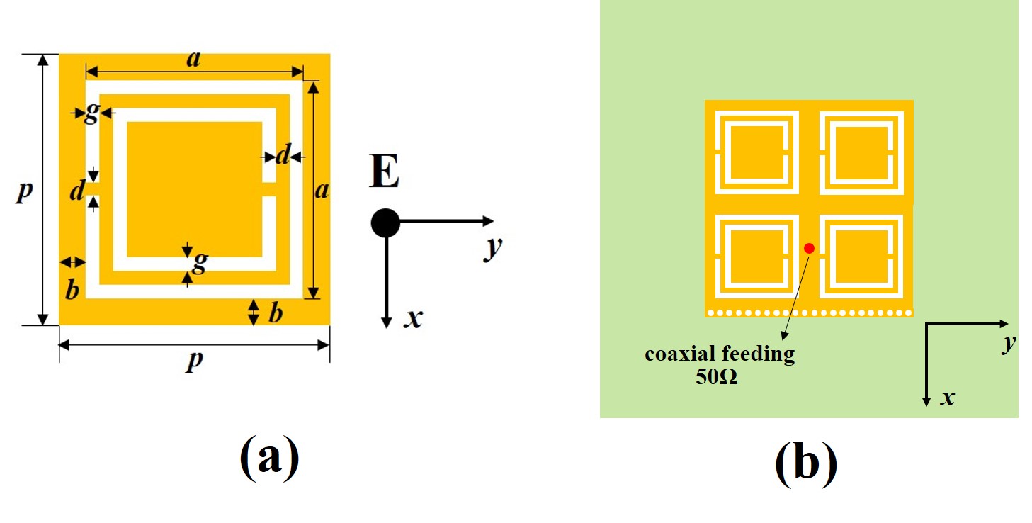
Figure 3: (a) One CSRR element and (b) the shorted patch antenna loaded with 2 2 CSRRs.
The two-step results provide an evident evolution map for the combination method to show its capability to effectively reduce the antenna resonant frequency. Considering the antenna volumes for these antennas are identical, it implies that the antenna with a lower resonant frequency has a smaller electrical size. Hence, a better size reduction effect can be achieved by the combination technique than only one method used solely.
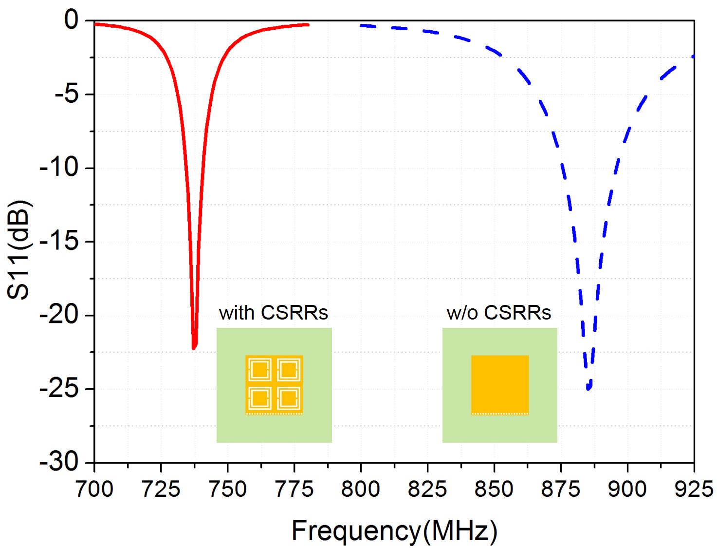
Figure 4: The simulated S11s for the shorted patch antennas with and without CSRRs.
IV. EXPERIMENTAL RESULTS
The designed shorted patch antenna with 2 2 CSRRs is experimentally demonstrated. The substrate is a kind of F4BMX dielectric with nominal = 2.2 and tan = 0.001, provided by Taizhou Wangling Corp. The measured S11, in contrast to the simulated one, is given in Figure 5. The fabricated shorted antenna with the CSRR metamaterial patch is also shown in the inset picture. It is fed by a 50- coaxial probe. From the measured S11, it is observed to resonate at 735 MHz ( = 408.16 mm) with the dB bandwidth (BW) of 6.8 MHz (0.93%). They agree well with the simulated results. The simulated resonant frequency from HFSS is 737 MHz with BW of 6.2 MHz (0.84%). The limited BW is resulted from the small antenna size [28, 29], which can also be found in other miniatureantennas [12].
The normalized antenna size is 0.127 0.123 (or 0.189 0.182). The substrate thickness is 12 mm or 0.03. Considering the dielectric is with a low index of = 2.2, the size-reduction effect is remarkable.
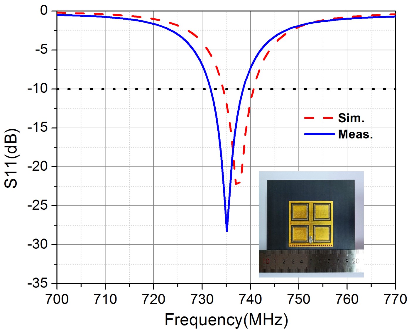
Figure 5: The S11s for the shorted CSRR patch antenna. The inset picture shows the fabricated antenna.
The radiation patterns for the shorted metamaterial antenna at the resonant frequency are given in Figure 6. For the shorted antenna, there is only one slot radiating the electromagnetic waves. Hence, its patterns on the E-plane as shown in Figure 6 (a) exhibit quasi-omnidirectional characteristics. They are much different from the conventional patch antenna in which two parallel slots work together. The H-plane patterns in Figure 6 (b) are yet similar with the conventional antenna.
The miniature antenna is with a notable backlobe. It is due to the electrically small ground plane. To suppress the backlobe, an effective method is to increase the ground size. Another limitation for the antenna is that the cross-polarizations are seen very large on the H-plane. They seem inevitable for shorted patch antennas that were also found in other designs with shorting walls [5–7]. Fortunately, the radiation fields in the broadside are still with good polarization purity.
The peak antenna gain is at the level of 2 dBi at the resonant frequency. The antenna gain can be moderately enhanced to about 3-4 dBi by increasing the directivity. It can be realized by enlarging the ground plane as to suppress the backlobe.
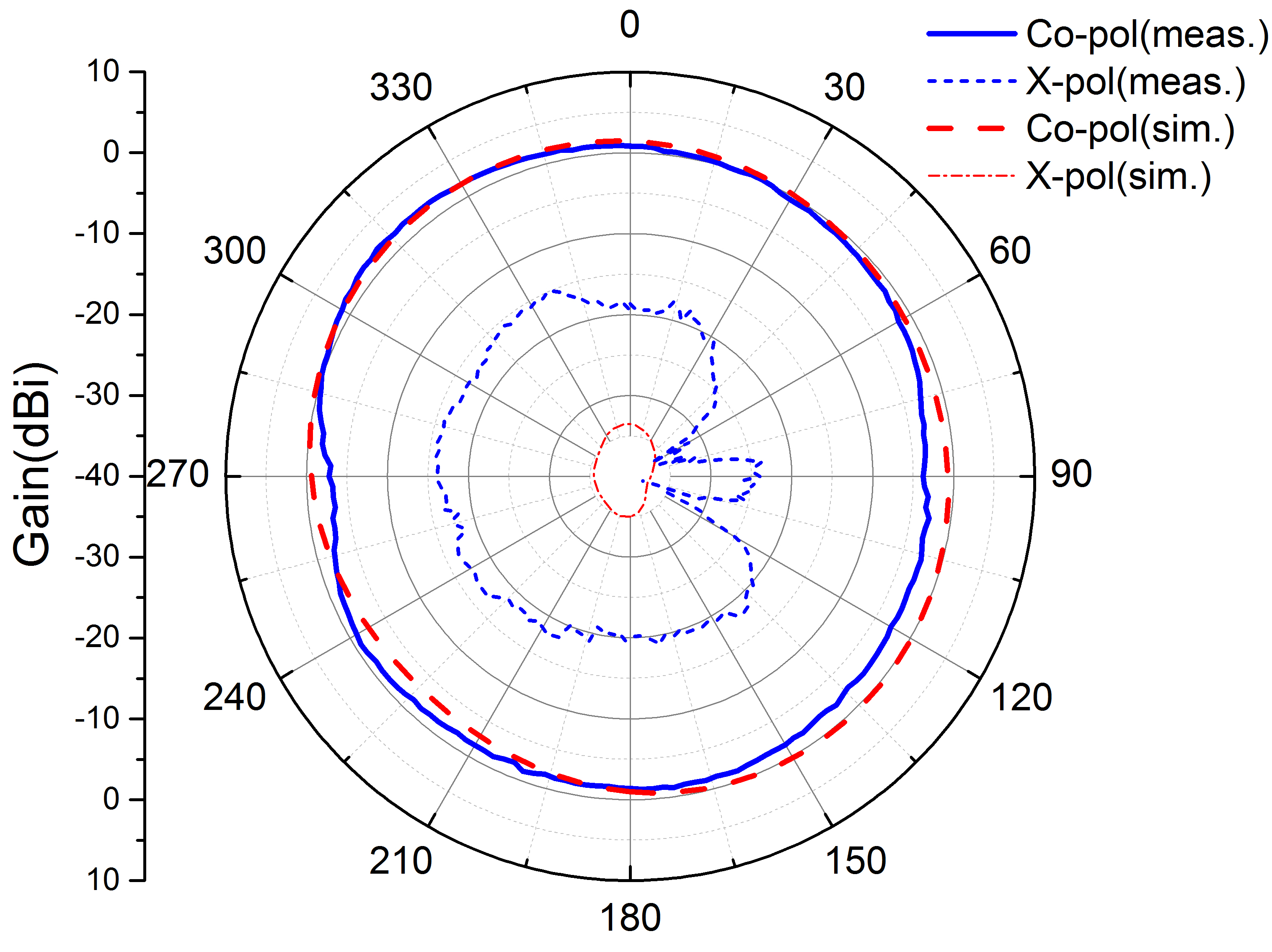
Figure 6: The radiation patterns for the shorted metamaterial antenna on the (a) E-plane and (b) H-plane.
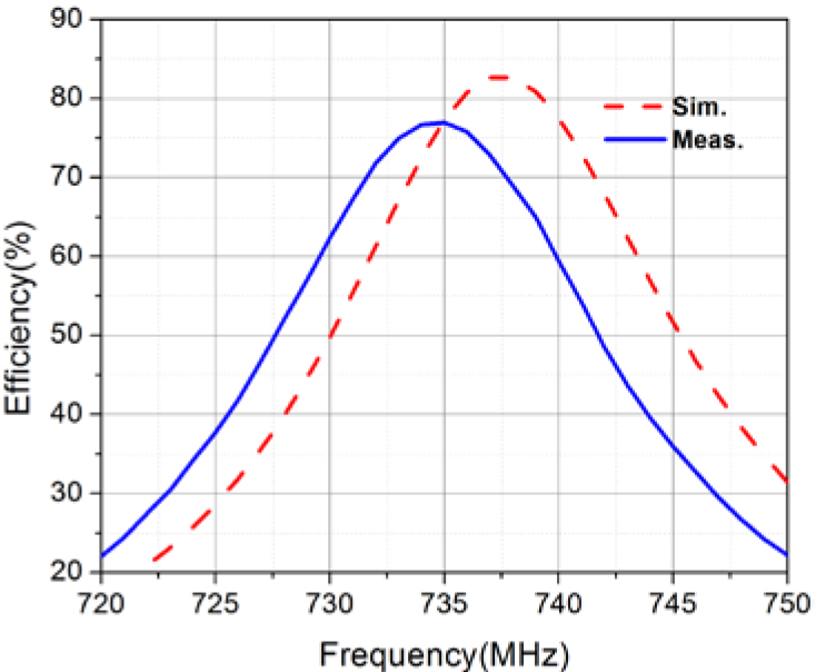
Figure 7: The antenna efficiency.
Figure 7 shows the simulated and measured antenna efficiency (). They are obtained with the G/D (gain/directivity) method. The directivity is calculated from the measured 3D radiation pattern data. The peak efficiency in measurement is about 77%. The simulated one is slightly higher as 82%. It proves that, although the new shorted antenna with CSRRs is very small, the total radiated power is still kept at an acceptably high level.
The performances for the shorted metamaterial antenna in this work are finally summarized in Table 2, in comparison with some other compact patch antennas operating in the UHF band below 1 GHz.
Table 2: Comparison of several compact patch antennas operating in the UHF band below 1 GHz
/% |
/dBi |
||||
| [12] | 0.16 0.16 | 0.01 | 0.3 | 83 | 1 |
| [19] | 0.077 0.077 | - | 0.83 | 19.8 | -3.9 |
| [21] | 0.2 0.2 | 0.028 | 0.5 | - | -7.9 |
| This work | 0.127 0.123 | 0.03 | 0.93 | 77 | 2 |
We have realized a small-sized UHF band patch antenna using the combination method of adding both a shorting wall and CSRRs. To make the antenna more compact, some other ways, e.g., a higher permittivity host substrate [12], [13] or magnetic material [14] may be incorporated into this powerful technique in future.
V. CONCLUSION
In conclusion, a small patch antenna is designed by combining two size-reduction methods as adding a shorting wall and CSRRs. Numerical calculations show that the resonant frequency can be significantly reduced by utilizing the combination method. One particular shorted patch antenna loaded with 2 2 CSRRs is experimentally studied, which is fabricated on a low permittivity substrate. The antenna resonates at 735 MHz. The patch size is 0.127 0.123. The measured efficiency is acceptably high as 77% that can meet the demands of the UHF band communications.
ACKNOWLEDGMENT
This work is supported by the National Natural Science Foundation of China under Grant 11904222 and the Natural Science Foundation of Shanghai under Grant 16ZR1446100.
REFERENCES
[1] R. Garg, P. Bhartia, I. Bahl, and A. Ittipiboon, Microstrip antenna design handbook, Artech House, MA, 2001.
[2] D. R. Jackson, “Microstrip antennas,” in Antenna Engineering Handbook, J. L. Volakis, Ed., McGraw Hill, NY, 2007, Ch. 7.
[3] E. J. Rothwell, and R. O. Ouedraogo, “Antenna miniaturization: definitions, concepts, and a review with emphasis on metamaterials,” J. Electromag. Waves Appl., vol. 28, pp. 2089-2123, 2014.
[4] S. Pinhas, and S. Shtrikman, “Comparison between computed and measured bandwidth of quarterwave microstrip radiators,” IEEE Trans. Antennas Propag., vol. 36, pp. 1615-1616, 1988.
[5] R. Chair, K. F. Lee, and K. M. Luk, “Bandwidth and cross-polarization characteristics of quarter-wave shorted patch antennas,” Microw. Opt. Technol. Lett., vol. 22, pp. 101-103, 1999.
[6] K. F. Lee, Y. X. Guo, J. A. Hawkins, R. Chair, and K. M. Luk, “Theory and experiment on microstrip patch antennas with shorting walls,” IEE Proc.-Microw. Antennas Propag., vol. 147, pp. 521-525, 2000.
[7] R. L. Li, G. DeJean, M. M. Tentzeris, and J. Laskar, “Development and analysis of a folded shorted-patch antenna with reduced size,” IEEE Trans. Antennas Propag., vol. 52, pp. 555-562, 2004.
[8] H. Iwasaki, and Y. T. Lo, “A circularly-polarized small-size microstrip antenna with a cross slot,” IEEE Trans. Antennas Propag., vol. 44, pp. 1399-1401, 1996.
[9] L. Desclos, “Size reduction of patch by means of slots insertion,” Microw. Opt. Technol. Lett., vol. 25, pp. 111-113, 2000.
[10] N. Herscovici, M. F. Osorio, and C. Peixeiro, “Miniaturization of rectangular microstrip patches using genetic algorithms,” IEEE Antennas Wireless Propag. Lett., vol. 1, pp. 94-97, 2002.
[11] R. C. Hansen, and M. Burke, “Antenna with magneto-dielectrics,” Microw. Opt. Technol. Lett., vol. 26, pp. 75-78, 2000.
[12] J. Huang, “Miniaturized UHF microstrip antenna for a Mars mission,” IEEE Antennas and Propagation Society International Symposium, pp. 486-489, 2001.
[13] J. S. Kula, D. Psychoudakis, W.-J. Liao, C.-C. Chen, J. L. Volakis, and J. W. Halloran, “Patch-antenna miniaturization using recently available ceramic substrates,” IEEE Antennas Propag. Mag., vol. 48, pp. 13-20, 2006.
[14] Z. Zheng, H. Zhang, J. Q. Xiao, and F. Bai, “Lowloss NiZn/Co2Z composite ferrite with almost equal values of permeability and permittivity for antenna applications,” IEEE Trans. Magn., vol. 49, pp. 4214-4217, 2013.
[15] X. M. Yang, Q. H. Sun, Y. Jing, Q. Cheng, X. Y. Zhou, H. W. Kong, and T. J. Cui, “Increasing the bandwidth of microstrip patch antenna by loading compact artificial magneto-dielectrics,” IEEE Trans. Antennas Propag., vol. 50, pp. 373-378, 2011.
[16] R. O. Ouedraogo, E. J. Rothwell, A. R. Diaz, K. Fuchi, and A. Temme, “Miniaturization of patch antennas using a metamaterial-inspired technique,” IEEE Trans. Antennas Propag., vol. 60, pp. 2175-2182, 2012.
[17] Y. Dong, H. Toyao, and T. Itoh, “Design and characterization of miniaturized patch antennas loaded with complimentary split ring resonator,” IEEE Trans. Antennas Propag., vol. 60, pp. 772-785, 2012.
[18] S. Li, A. Z. Elsherbeni, Z. Ding, and Y. Mao, “A metamaterial inspired compact miniaturized triple-band near field resonant parasitic antenna for WLAN/WiMAX applications,” Applied Computational Electromagnetics Society (ACES) Journal, vol. 35, pp. 1539-1547, 2020.
[19] K. Buell, H. Mosallaei, and K. Sarabandi, “A substrate for small patch antennas providing tunable miniaturization factor,” IEEE Trans. Microw. Theory Technol., vol. 54, pp. 135-146, 2006.
[20] F. Bilotti, A. Toscano, and L. Vegni, “Design of spiral and multiple split-ring resonators for the realization of miniaturized metamaterial samples,” IEEE Trans. Antennas Propag., vol. 55, pp. 2258-2267, 2007.
[21] S. Jahani, J. Rashed-Mohassel, and M. Shahabadi, “Miniaturization of circular patch antennas using MNG metamaterials,” IEEE Antennas Wireless Propag. Lett., vol. 9, pp. 1194-1196, 2010.
[22] S. Kumar, and D. K. Vishwakarma, “Miniaturisation of microstrip patch antenna using an artificial planar magneto-dielectric meta-substrate,” IET Microw. Antennas Propag., vol. 10, pp. 1235-1241, 2016.
[23] X. Xu, and J. Wei, “Miniaturisation design of patch antenna using a low-profile mushroom type meta-substrate tailored with high permittivity,” IET Microw. Antennas Propag., vol. 12, pp. 1216-1221, 2018.
[24] G. Dai, X. Xu, and X. Deng, “Size-reduced equilateral triangular metamaterial patch antenna designed for mobile communications,” Applied Computational Electromagnetics Society (ACES) Journal, vol. 36, pp. 1026-1030, 2021.
[25] Q. Huang, and X. Xu, “Design of a miniaturized UHF band patch antenna inspired by the metamaterial technology,” Asia-Pacific Conference on Antennas and Propagation, pp. 1-2, 2020.
[26] H. Lu, X. Xu, and F. Sun, “Miniaturized UHF band microstrip antenna designed with spiral metamaterial inclusions,” International Applied Computational Electromagnetics Society Symposium, pp. 1-2, 2021.
[27] J. D. Baena, J. Bonache, F. Martin, R. Marques, F. Falcone, T. Lopetegi, M. A. G. Laso, J. Garcia, I. Gil, and M. Sorolla, “Equivalent-circuit models for split-ring resonators and complementary split-ring resonators coupled to planar transmission lines,” IEEE Trans. Microw. Theory Tech., vol. 53. pp. 1451-1461, 2005.
[28] L. J. Chu, “Physical limitations of omnidirectional antennas,” J. Appl. Phys., vol. 19, pp. 1163-1175, 1948.
[29] J. S. McLean, “A re-examination of the fundamental limits on the radiation Q of electrically small antennas,” IEEE Trans. Antennas Propag., vol. 44, pp. 672–676, 1996.
BIOGRAPHIES

Qianling Huang was born in Nantong, China, in 1996. She received the M.S. degree in electronics and communication engineering from Shanghai University, Shanghai, China, in 2020.Her research interest includes antenna miniaturization technology and electromagnetic metamaterials.

Xiaofei Xu received the B.S. degree in 2007 and the Ph.D. degree in 2011, both from Nanjing University, Nanjing, China.He is currently with the School of Communication and Information Engineering, Shanghai University, Shanghai, China.Dr. Xu’s research areas include electromagnetics, antennas, and microwave technology. He has authored more than 50 papers published in peer-reviewed journals and conference proceedings. He also serves a number of journals and society workshops as the reviewer or organizer.

Ruiheng Zhang was born in Shanghai, China, in 1995. He received the M.S. degree in electronics and communication engineering from Shanghai University, Shanghai, China, in 2020.
His current research interest includes antenna and RF technology for base stations and terminals for fifth-generation (5G) communications.
ACES JOURNAL, Vol. 37, No. 2, 209–214.
doi: 10.13052/2022.ACES.J.370209
© 2021 River Publishers