Research and Design of Radar System for Respiratory and Heartbeat Signal Detection
Ziliang Xia, Xinhuai Wang, Xin Li, and Yin Xu
National Key Laboratory of Science and Technology on Antennas and Microwave
Xidian University, Xi’an, Shaanxi 710071, China
zlxia@stu.xidian.edu.cn, xinhuaiwang@xidian.edu.cn, xli7@stu.xidian.edu.cn, xuyin@xidian.edu.cn
Submitted On: November 26, 2021; Accepted On: January 13, 2022
Abstract
The respiratory and heartbeat signals can accurately reflect the health status of the tester, which is of great clinical significance. Compared with the traditional contact detection method, the non-contact radar detection method does not require the tester to wear any sensor equipment and will not cause any discomfort to the tester. The frequency modulated continuous wave (FMCW) radar has the characteristics of simple structure, high resolution, strong stability, and low transmission power and is used for the detection of respiratory and heartbeat signals. This paper designs a low-power, low-cost respiratory, and heartbeat signal detection system based on FMCW radar. In addition, the variational modal decomposition (VMD) method is used to separate respiration and heartbeat signals to obtain accurate respiration and heartbeat rates. The results show that the radar system for detecting respiratory and heartbeat signals has high detection accuracy.
Keywords: Frequency modulated continuous wave (FMCW), heartbeat signals, respiratory signals, variational modal decomposition (VMD).
I. INTRODUCTION
According to the latest report, 330 million people have cardiovascular disease in China, and the death rate of this disease ranks first [1]. Real-time monitoring of patients’ respiratory and heartbeat signals can effectively reduce accidents caused by this disease. Therefore, a detection device is needed to monitor the human body’s respiratory and heartbeat rate in real time. Traditional medical contact detection equipment requires the tester to wear electrodes or sensors during the detection process, and the tester’s physical activity is restricted by the device [2]. The non-contact detection device does not need to wear any sensors and mainly realizes the detection of the tester’s physical information through wireless signals. The respiratory and heartbeat signal detection radar system is based on electromagnetic signals for measurement, which can penetrate obstacles such as clothes and quilts. It can be used in medical diagnosis, home health monitoring, and other occasions [3].
At present, non-contact radar detection technology has developed rapidly in the field of physiological detection. Biological radar was designed to detect abnormalities in cardiopulmonary information in 2004 [4]. A 5.8-GHz continuous wave radar detects the baby’s vital signs in [5, 6]. Zito’s research team has carried out research on the non-contact detection device based on ultra-wideband radar and successfully developed a set of cardiopulmonary signal detection device [7]. In [8], a 9.6-GHz frequency modulated continuous wave (FMCW) radar is used to detect respiration and heart rate, and the influence of harmonic of respiratory signal on estimation of heart rate is not eliminated. Zhang et al. used FMCW radar of 24.15 GHz to extract the heart rate signal, and the method used to extract the heartbeat signal is not accurate [9]. In [10], the author evaluated the results of vital signs detection by typical antennas.
During normal cardiopulmonary activities such as respiratory and heartbeat, the surface of the human thoracic cavity will produce periodic weak movements. The electromagnetic signal emitted by the radar passes through the slightly moved thoracic cavity and undergoes a Doppler effect, which causes the phase of the echo signal to change. The phase change corresponds to the micro-movement of the chest cavity, hiding the respiratory and heartbeat signals. Due to the close frequency band range of respiratory and heartbeat signals, the use of band-pass filter to separate respiratory and heartbeat signals cannot effectively solve the problem of respiratory harmonic interference on heartbeat signals [11]. Wavelet transform can extract respiratory and heartbeat signals from life signals by selecting appropriate wavelet basis functions, and it is difficult to select appropriate wavelet basis functions [12]. Empirical mode decomposition (EMD) is an adaptive signal processing method proposed by Huang et al. in 1998 [13], which can deal with nonlinear and non-stationary signals very well. The disadvantage of EMD is that the decomposed intrinsic modal functions (IMFs) have modal aliasing. Ensemble empirical mode decomposition (EEMD) proposed by Wu et al. [14, 15] reduces the problem of modal aliasing by adding white noise. However, due to the limited number of noise additions, noise residue is prone to appear. Complete ensemble empirical mode decomposition with adaptive noise (CEEMDAN) proposed by Torres et al. [16] can solve the noise residual problem with less averaging by adding adaptive white noise at each stage of the decomposition. There may be false components in the result of its decomposition. Variational modal decomposition (VMD) [17] can effectively avoid modal aliasing and false components. Therefore, this paper proposes an algorithm based on VMD to process radar life signals to realize the separation and extraction of respiratory and heartbeat signals.
II. DETECTION SCHEME
A. Respiration and heartbeat signal detection
The detection of respiratory and heartbeat signals uses FMCW radar, which can measure the distance and speed of the target. In addition, the electromagnetic wave signal emitted by the radar has a very narrow wavelength and a wide bandwidth, which can improve the system’s high sensitivity and range resolution. Shown in Figure 1 is the detection schematic diagram of FMCW radar.
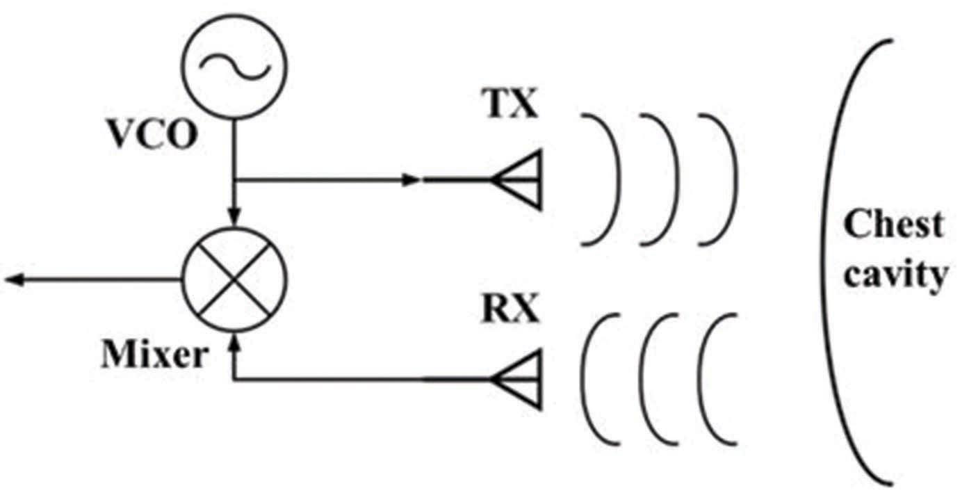
Figure 1: Schematic diagram of FMCW radar detection.
FMCW is generated by the voltage-controlled oscillator (VCO) as the local oscillator signal of the radar system. The power divider is divided into two parts. One part of the signal is used as the transmitting signal to radiate outward through the transmitting antenna, and the other part is used as the local oscillator input of the receiver to mix with the echo signal received by the receiving antenna to obtain an intermediate frequency signal. The frequency and phase information of the intermediate frequency signal contains the information of the chest cavity micro-movement. Figure 2 shows the FMCW using sawtooth modulation.
The transmitted signal can be expressed as
| (1) |
where f is the working frequency of sensor, B is the bandwidth of radar, and T is the period of saw tooth wave transmitting signal. When the signal is reflected after it encounters an object, the reflected signal can be regarded as the delay form of the transmitting signal:
| (2) |
t = 2R/c is the time taken for the electromagnetic wave from transmitting to receiving, R is the distance between the sensor and the object under test, and c is the speed of light. The intermediate frequency signal b(t) of the object to be measured is obtained by mixing and filtering the received signal
| (3) |
For a single object, the intermediate frequency signal after mixing is a sine curve with frequency f= 4BRt/cT and phase = 4R/. When the chest wall displacement of human body is detected, the phase of intermediate frequency signal in the distance unit of the measured object can be measured with time. The phase change is
| (4) |
Since the amplitude of chest wall vibration is very small, it can be assumed that the vibration signal x(t) is in the same distance element during vibration. Assuming that the object is in the mth distance element, the vibration signal can be obtained by calculating the phase information corresponding to the mthdistance element at time nT
| (5) |
where n is the index of LFM pulse and T is the time interval of continuous measurement.
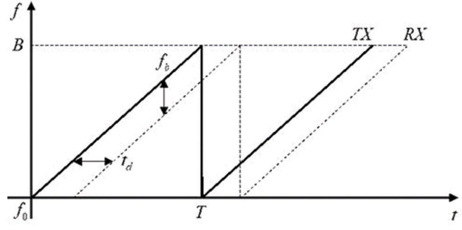
Figure 2: The FMCW using sawtooth modulation.
B. Respiration and heartbeat signal decomposition
Since the human heart and lungs have a certain physiological coupling relationship, the higher harmonics of the respiratory signal may overlap with the heartbeat signal; so the separation of the respiratory signal and the heartbeat signal based on VMD are proposed. The VMD method is used to solve the variational problem. Its purpose is to decompose the original signal f into k IMFs with a finite bandwidth and a center frequency.
The algorithm flow of decomposition of respiratory and heartbeat signals is shown in Figure 3. After passing through the rectangular window, the vital signs need to be preprocessed by filtering and de-noising to be used as the input signal of VMD. The appropriate decomposition level k is set to reduce the aliasing phenomenon of decomposed natural mode components. The value of k is selected according to the actual measured signals. The decomposed natural mode components are transformed by 1024 points fast Fourier transform (FFT) to obtain the spectrum information. Since the frequency of the normal person’s breathing component ranges from 0.2 to 0.8 Hz, and the frequency range of the heartbeat component ranges from 0.8 to 2 Hz, the frequency selector can be used to obtain the breathing signal and the heartbeat signal.
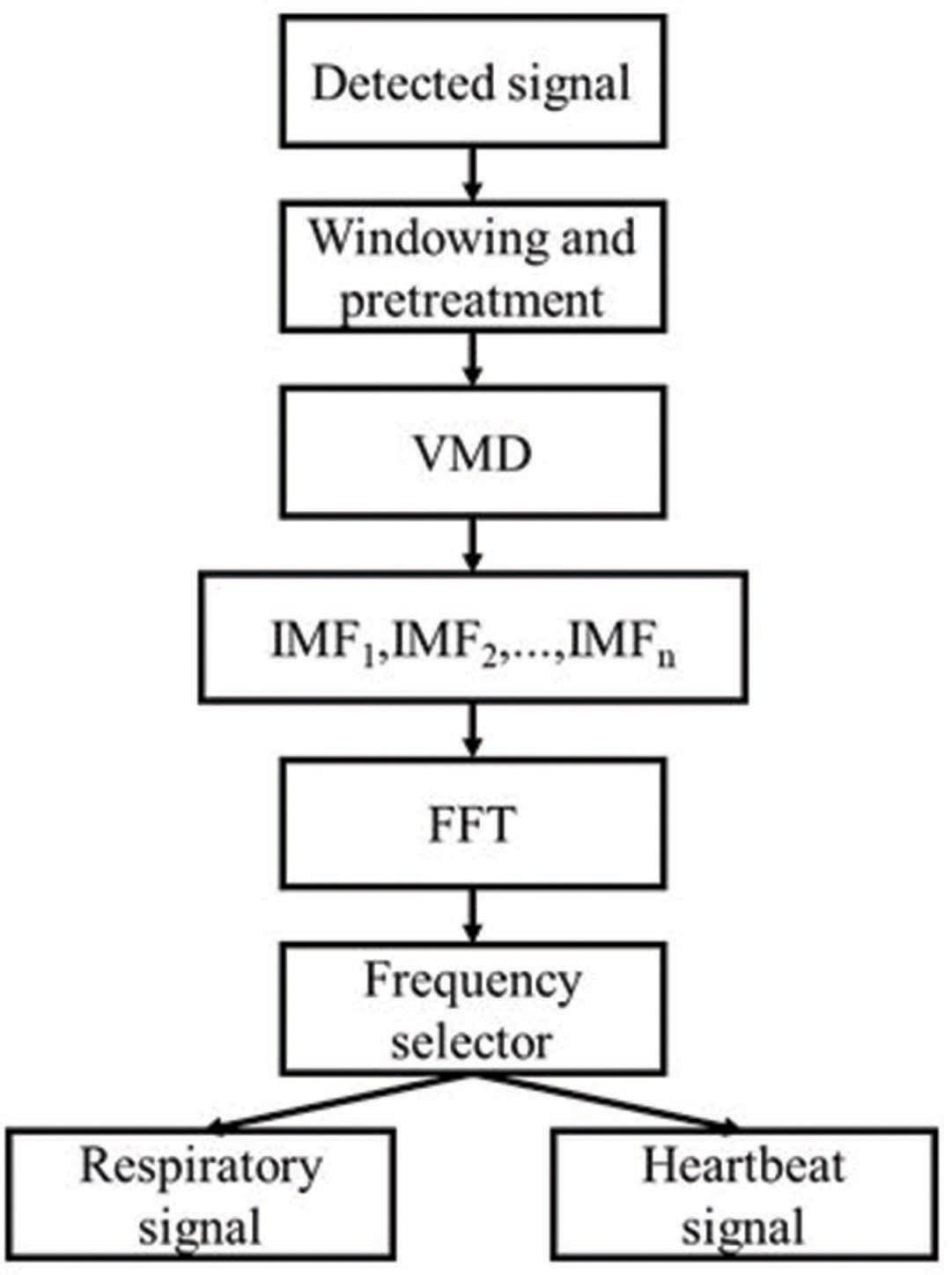
Figure 3: The algorithm flow of decomposition of respiratory and heartbeat signals.
III. RADAR SYSTEM DESIGN
A. Hardware circuit design
The key indicators of FMCW radar include the start frequency of the radio frequency signal, the signal bandwidth, the slope of the ramp signal, and the repetition period. Table 1 shows the relevant parameters of the radar system hardware platform.
Table 1: The relevant parameters of the radar system hardware platform
| Index | Numerical value |
|---|---|
| Start frequency | 24 GHz |
| Bandwidth | 500 MHz |
| Ramp signal slope | 0.5 MHz/s |
| Repeat frequency | 100 Hz |
The detection range of the radar is designed to be 5 m, and the signal bandwidth is selected to be 500 MHz under a certain range resolution, and the corresponding range resolution is 0.3 m. The slope of the ramp signal is set to 0.5 MHz/s, and the corresponding intermediate frequency signal frequency is about 16 kHz, thereby reducing the requirements of the back-end circuit. The start frequency affects the detection accuracy of weak motion information. When there is a 1-mm micro-movement, the phase of the 24-GHz radio frequency signal changes 0.32. The re-frequency period determines the update frequency of the demodulation information, and it is set to 100 Hz to meet the frequency estimation requirement. The framework of the radar system is shown in Figure 4. The entire radar system includes transceivers, antennas, intermediate frequency conditioning circuits, and microcontrollers. The system is based on the following integrated chips: radio frequency transceiver chip BGT24MTR11, phase-locked loop chip LMX2491, operational amplifier chip LMX321, and microcontroller chip STM32F303.
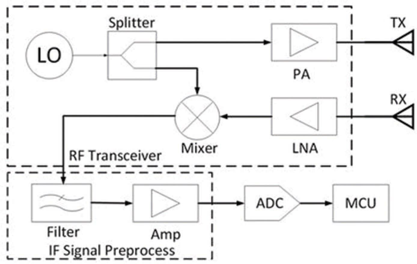
Figure 4: The framework of the radar system.
The overall working principle of the circuit is as follows: First, the RF transmitter generates a 24-GHz FMCW signal and radiates it through the transmitting antenna. The FMCW start frequency, signal bandwidth, and repetition period are adjusted through the phase-locked loop to adjust the VCO input voltage control; then the receiving antenna receives the radio frequency signal carrying the test target information, through the quadrature mixer and the transmitted signal down-mixing to obtain two orthogonal intermediate frequency signals; the intermediate frequency signal is amplified and filtered by the intermediate frequency conditioning circuit. The analog-to-digital converter samples the digital signal; the final digital signal is analyzed and processed in the microprocessor.
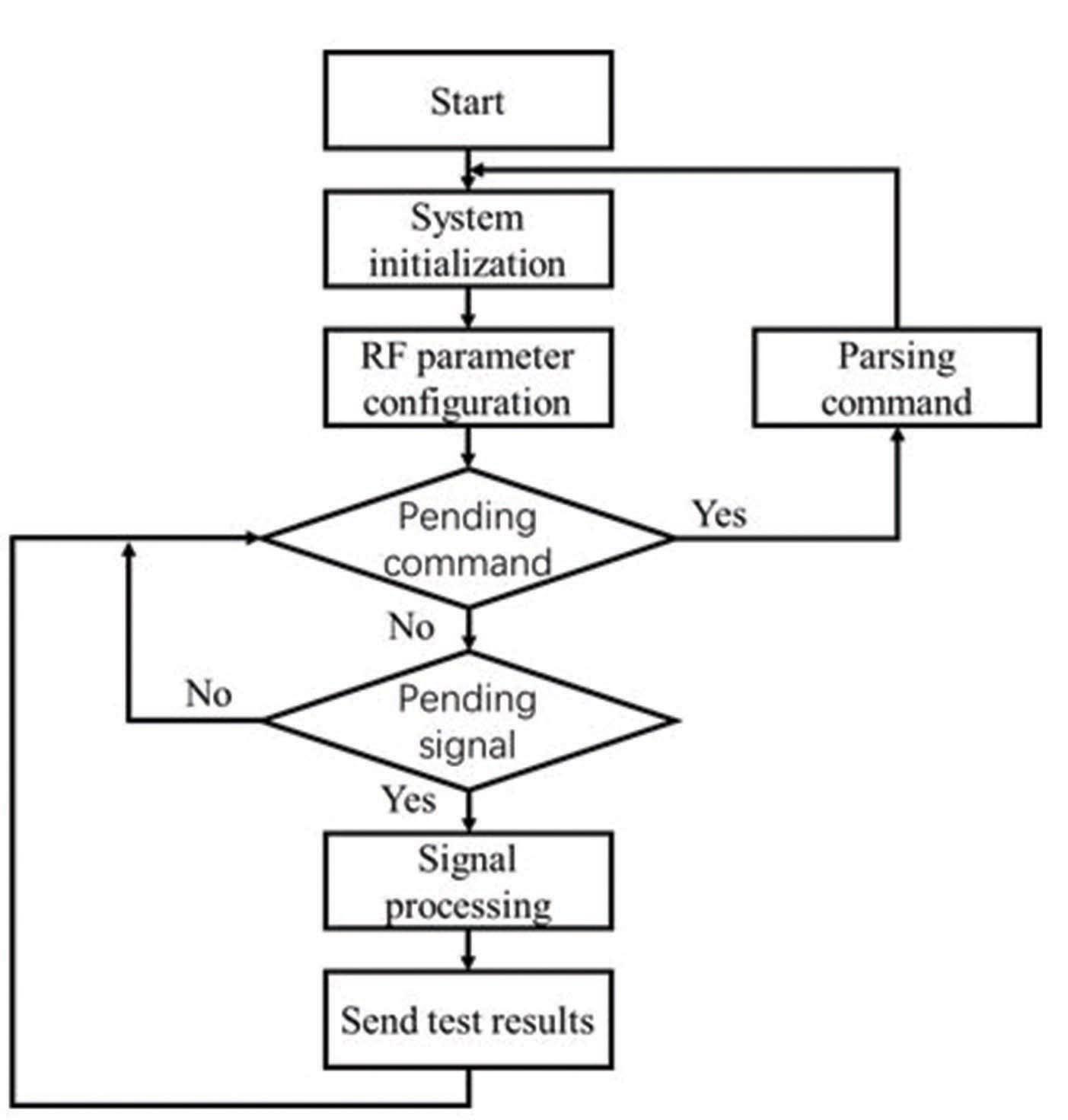
Figure 5: The system control process.
B. System flow control
The system control process includes the system initialization process, the judgment waiting process, and the signal processing process. Figure 5 shows the system control process. In the initialization process, the microcontroller clock system and internal storage unit are first configured, the preset radio frequency signal parameters are read, and the internal registers of the phase-locked loop chip and the radio frequency transceiver chip are configured through the analog serial peripheral interface (SPI). The judgment waiting process is used to judge the following two events, that is, whether there is a user command to be responded to and whether there is radar data to be processed. When there is a user command to be responded to, parse the command and jump to the initialization process to reinitialize the system parameters with new parameters. When there is a radar signal to be processed, jump to the signal processing process. If neither event occurs, continue to wait until the event happened. The signal processing flow is used to process the radar data analysis, including the extraction of the micromotion signal parameters and upload the detection results through the universal asynchronous receiver/transmitter (UART) or SPI.
IV. EXPERIMENT AND ANALYSIS
A. Device and experiment
The designed respiratory and heartbeat signal detection radar system is shown in Figure 6. The physical size of the PCB board is 40 mm 40 mm.
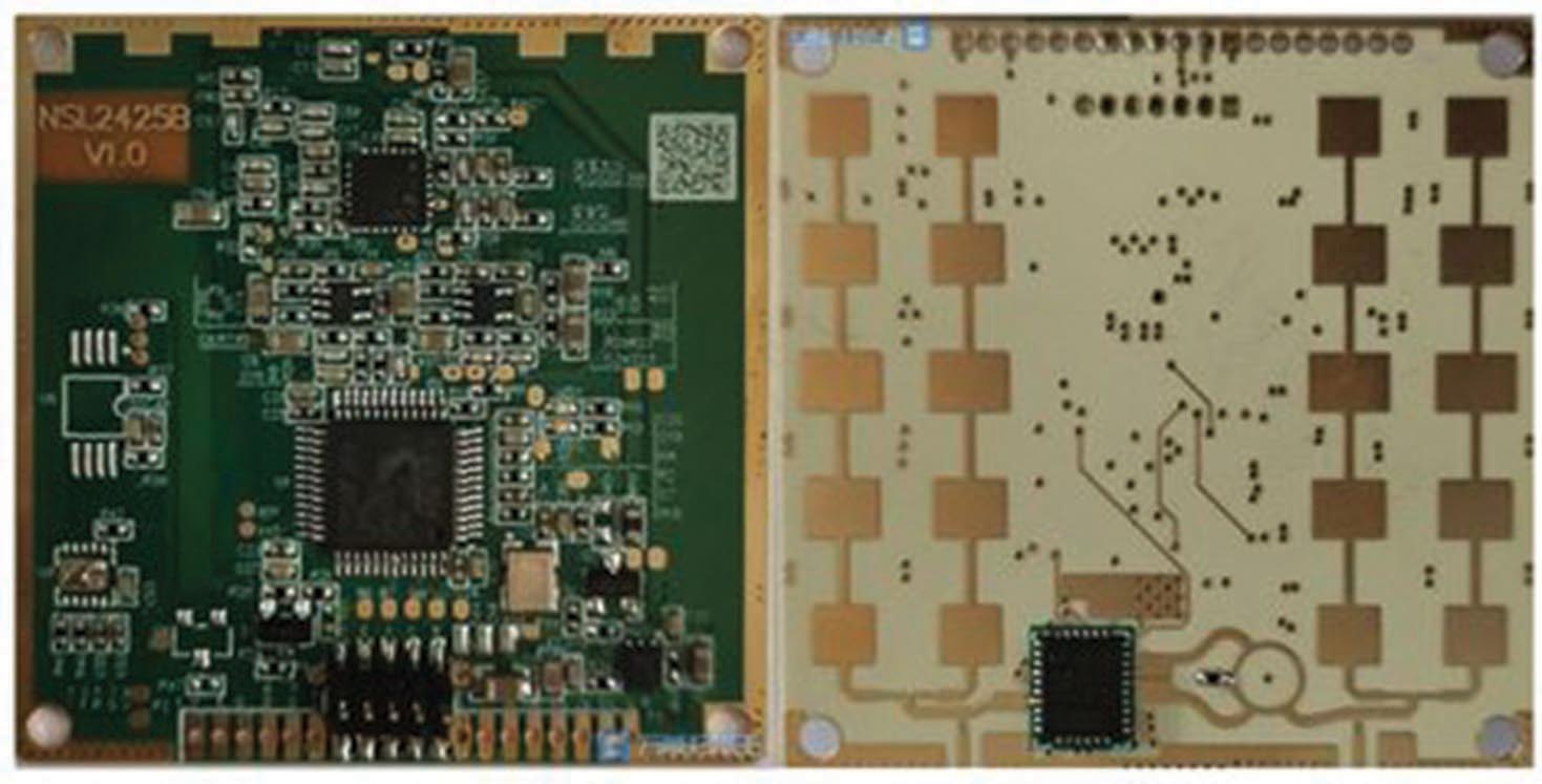
Figure 6: The respiratory and heartbeat signal detection radar system.
In order to test the system’s power consumption and RF signal quality, we built a test scenario as shown in Figure 7. Test instruments include laptop computers, J-LINK simulators, power supplies, oscilloscopes, signal generators, and spectrum analyzers. The maximum power of the system is 1.25 W, and the standard universal serial bus (USB) interface can meet the power supply requirements of the system. Two 2 5 microstrip patch antennas are used for Tx and Rx.
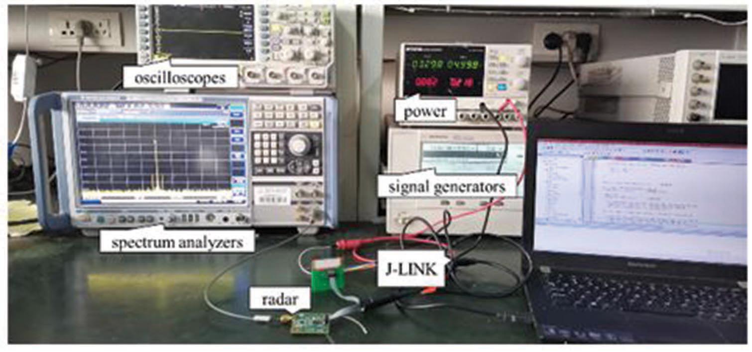
Figure 7: Testing scenarios.
The parameters of the radio frequency signal emitted by the radar system are shown in Table 1. Figure 8 shows the frequency spectrum of the FMCW signal under power peak hold. It can be seen from the figure that the parameters of the actual transmitted signal are basically consistent with the preset values.
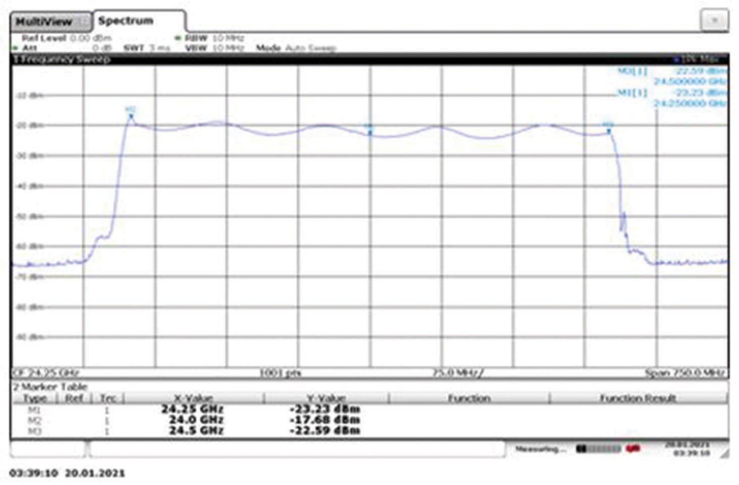
Figure 8: FMCW output power test.
B. Results and analysis
During the test, the tester remains at rest and is 1.5 m away from the antenna. The ADC with a sampling rate of 20 Hz is used to sample the chest micro-movement information detected by the radar system. The signal after windowing and preprocessing is shown in Figure 9. Since the human body’s normal respiratory and heartbeat frequencies are below 3 Hz, when using the VMD algorithm to decompose the processed signal, the number of IMFs does not need to be too much. The value of k adopts an adaptive method. In this signal, the value of k is 4. As shown in Figure 10, VMD can successfully decompose the respiratory and heartbeat signals in the signal. The IMF is the same frequency as the peak of the chest wall displacement signal spectrum. The IMF is twice the frequency of the peak of the IMF spectrum; so IMF is the second harmonic of IMF. The frequency of the peak of the IMF spectrum is 1.426 Hz. The corresponding heart rate is 42 beats, which is consistent with half of the pulse rate. The IMF is five times the frequency of the peak of the IMF spectrum; so IMF is the fifth harmonic of IMF.
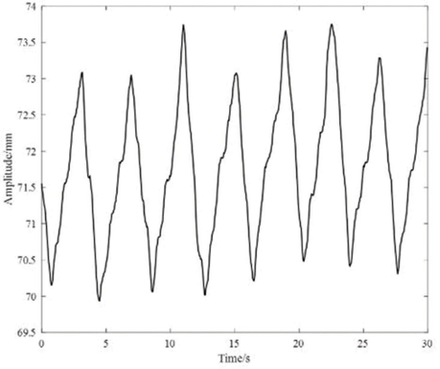
Figure 9: Chest micromotion signal detected by radar system.
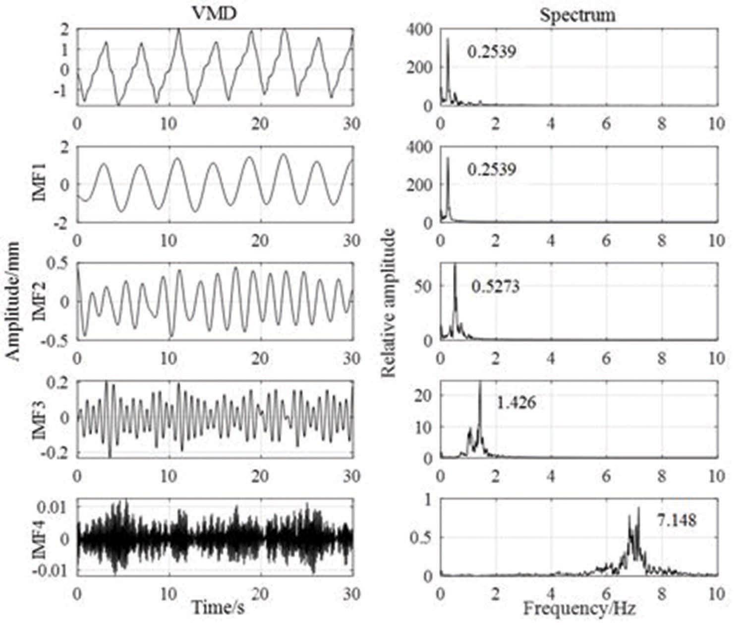
Figure 10: IMFs of VMD and spectrums.
Eight different testers at the same distance are detected. Compared with the ECG monitor, the correct rates of respiratory frequency and heart frequency of VMD decomposition are obtained in Table 2. It can be seen that the accuracy of respiratory rate and heart rate of eight testers are all above 97% and 96%, respectively. The results show that the FMCW radar system designed to detect human respiratory and heartbeat signals has achieved the expected purpose. The separation algorithm based on the VMD method we designed is very effective for separating the respiratory and heartbeat signals from the thoracic micromotionsignals.
Table 2: Frequency and correct rates of the separated respiratory and heartbeat signals
| Testers | Respiratory frequency/Hz | Heartbeat frequency/Hz | Respiratory/heartbeat accuracy/% | |
| 1 | 0.1953 | 1.221 | 97.7 | 96.9 |
| 2 | 0.2539 | 1.426 | 98.4 | 97.0 |
| 3 | 0.3418 | 1.514 | 97.8 | 96.8 |
| 4 | 0.2441 | 1.536 | 97.6 | 97.7 |
| 5 | 0.2667 | 1.367 | 99.9 | 97.0 |
| 6 | 0.2510 | 1.27 | 97.7 | 97.1 |
| 7 | 0.2344 | 1.346 | 99.8 | 98.5 |
| 8 | 0.3167 | 1.420 | 99.0 | 98.2 |
V. CONCLUSION
In this paper, a respiration and heartbeat signal detection radar system is designed. The radar transmits FMCW signals to the chest cavity of the human body and uses the Doppler frequency offset effect to obtain the information of the chest cavity micro-movements caused by respiration and heartbeat movement, thereby achieving the purpose of non-contact detection of the target’s respiration and heartbeat rate. In order to separate the respiration and heartbeat signals from the thoracic micromotion signals, we propose a method for separating respiration and heartbeat signals based on VMD. The detection results are very accurate, the correct rate of respiratory rate is more than 97%, and the correct rate of heart rate is more than 96%. The system can provide help for the monitoring of cardiovascular patients.
REFERENCES
[1] The Writing Committee of the Report on Cardiovascular Health and Diseases in China, “Report on cardiovascular health and diseases burden in china: an updated summary of 2020,” Chinese Circulation Journal., vol. 36, pp. 521–545, Jun. 2021.
[2] Y. H. Kwak, et al., “Flexible heartbeat sensor for wearable device,” Biosensors & Bioelectronics., vol. 94, pp. 250–255, Mar 2017.
[3] F. Q. Qi, et al., “Detection and classification of finer-Grained human activities based on stepped-frequency continuous-wave through-wall radar,” Sensors., vol. 16, no. 6, pp. 885–901, Jun. 2016.
[4] A. D. Droitcour, et al., “Range correlation and I/Q performance benefits in single-chip silicon Doppler radars for noncontact cardiopulmonary monitoring,” IEEE Transactions on Microwave Theory & Techniques., vol. 52, no. 3, pp. 838–848, Mar. 2004.
[5] M. Brink, C. H. Müller, and C. Schierz, “Contact-free measurement of heart rate, respiration rate, and body movements during sleep,” Behavior Research Methods., vol.38, no. 3, pp. 511–521, Aug. 2006.
[6] M. Uenoyama, T. Matsui, K. Yamada, et al., “Non-contact respiratory monitoring system using a ceiling-attached microwave antenna,” Medical & Biological Engineering & Computing., vol. 44, no. 9, pp. 835–840, 2006.
[7] Y. Xu, J. Chen, S. Dai, et al., “Experimental study of UWB pulse radar for life detection,” Instrumentation, Measurement, Computer, Communication and Control., 2011 pp. 729–732.
[8] L. Anitori, A. D. Jong, F. Nennie, “FMCW radar for life-sign detection,” IEEE Radar Conference., 2009. pp. 1–6.
[9] D. Zhang, M. Kurata, T. Inaba, “FMCW radar for small displacement detection of vital signal using projection matrix method,” International Journal of Antennas and Propagation., 2013, pp. 1–5.
[10] R. S. Mpanda, et al. “Design and evaluation of typical antennas for monitoring vital signs,” Applied Computational Electromagnetics Society journal., vol. 34, no. 3, pp. 497-505, Mar. 2019.
[11] D. R. Morgan, M. G. Zierdt, “Novel signal processing techniques for Doppler radar cardiopulmonary sensing,” Signal Processing., vol. 89, no. 1,pp. 45–66, 2009.
[12] M. Y. Li, J. Lin, “Wavelet-transform-based data-length-variation technique for fast heart rate detection using 5.8-ghz CW Doppler radar,” IEEE Transactions on Microwave Theory and Techniques., vol.66, no. 1, pp. 568–576, 2018.
[13] N. E. Huang, Z. Shen, S. R. Long, et al., “The empirical mode decomposition and the Hilbert spectrum for nonlinear and non-stationary time series analysis,” Proceedings of the Royal Society of London. Series A: Mathematical, Physical and Engineering Sciences., vol. 454, no. 1971, pp. 903–995, 1998.
[14] Z. Wu, N. E. Huang, X. Chen, “The multi-dimensional ensemble empirical mode decomposition method,” Advances in Adaptive DataAnalysis., vol. 1, no. 3, pp. 339–372, 2009.
[15] Z. Wu, N. E. Huang, “Ensemble empirical mode decomposition: a noise-assisted data analysis method,” Advances in adaptive data analysis., vol.1, no. 1, pp. 1–41, 2009.
[16] M. E. Torre, M. A. Colominas, et al., “A completeensemble empirical mode decomposition with adaptive noise,” IEEE International Conference on Acoustics, Speech and Signal Processing., 2011, pp. 4144–4147.
[17] K. Dragomiretskiy, D. Zosso, “Variational mode decomposition,” IEEE Transactions on Signal Processing., vol.62, no. 3, pp. 531–544, 2014.
BIOGRAPHIES

Ziliang Xia received the B.S. degree from the Xidian University, Xi’an, China, in 2019. He is currently working toward the M.S. degree in electromagnetic field and microwave technology with the same university. His recent research interests are mainly in the design of circuits and algorithms.

Xinhuai Wang received the B.Eng., M.Eng., and Ph.D. degrees from Xidian University, Xi’an, China, in 2004, 2007, and 2011, respectively. Since 2011, he has been with Collaborative Innovation Center of Information Sensing and Understanding, Xidian University and Science and Technology on Antenna and Microwave Laboratory, Xidian University, as a Lecturer and Associate Professor. He has authored or coauthored more than 60 international and regional refereed journal papers. His recent research interests are mainly in the design of microwave components system.
Dr. Wang is a member of IEEE and a senior member of CIE.

Xin Li was born in 1995. He received the B.S. degree from the Xidian University, Xi’an, China, in 2019. He is currently working toward the M.S. degree in electromagnetic field and microwave technology with the same university. His recent research interests are mainly in the signal processing and the design ofcircuits.

Yin Xu received the B.Eng., M.Eng., and Ph.D. degrees from Xidian University, Xi’an, China, in 2006, 2009, and 2013, respectively.
She is working at Xidian University as an associate professor. Her recent research interests are mainly in the electromagnetic field and microwave technology.
ACES JOURNAL, Vol. 37, No. 1, 102–108.
doi: 10.13052/2022.ACES.J.370112
© 2021 River Publishers