Model of Ferrite-cored Driver-pickup Coil Probe Application of TREE Method for Eddy Current Nondestructive Evaluation
Siquan Zhang and Chengkai Ye
Department of Electrical and Automation
Shanghai Maritime University, Shanghai 201306, China
sqzhang@shmtu.edu.cn
Submitted On: December 11, 2021; Accepted On: July 8, 2022
Abstract
An analytical model of a driver-pickup coil probe, consists of a cylindrical ferrite core, located above a layered conductor is presented. The truncated region eigenfunction expansion (TREE) method is used and the solution region is truncated with a certain radius around markedasmathitalicz axis. First, the magnetic vector potential of each region of filamentary coil problem is derived and solved with variables separation method using boundary and interface conditions, and then the rectangular cross-section coil problem is solved with superposition method. The expression of induced voltage in pickup coil is obtained and can be calculated with software such as Matlab or Mathematica. Using the proposed analytical model, the influence of the excitation frequency and excitation current in the driver coil on the responses of the pickup coil is examined. Experiments are performed, and the changes of voltage induced in the pickup coil due to the conductor are measured at different excitation frequencies and excitation currents. The analytical calculation results agree with the experimental results very well, verifying the correctness of the proposed analyticalmodel.
Index Terms: Eddy current testing, ferrite cored driver-pickup probe, induced voltage, magnetic vector potential, truncated region eigenfunction expansion method.
I. INTRODUCTION
Eddy current testing (ECT) is one of the conventional methods used to evaluate the characteristics and defects of conductive materials. Due to its extremely high sensitivity and no contact need with test pieces, ECT is widely used in the safety assessment of critical components in industry and manufacturing.
Generally, an absolute ECT probe has one single coil, which is excited by a sinusoidal current and generates an eddy current in the conductor under test, the magnetic field reflected from the eddy current causes the impedance change of the coil. The signal of this impedance change can be measured and used to evaluate the conductive material [1–3].
In addition to single-coil probes, the differential ECT probes have two or more coils. Each coil has excitation and sensing functions, the coils are usually wound in opposite directions. When they are located on the same conductor, no signal is generated. When one coil is over the defective material and the other coil is over the good material, a very distinct differential signal can be observed [4, 5].
There are also probes in which excitation and sensing are performed by separate coils. For example, the widely used ECT driver-pickup probe consists of one or more driver coils and pickup coils. The detection process can be achieved by measuring the change of the induced voltage of the pickup coil close to the excitation coil [6, 7].
Many analytical methods have been developed for calculation the response of air-cored pickup coil for driver-pickup coil probe. Using the Fourier transform method, the expression of induced voltage in pickup coil above conductor was presented, both coils were air-cored, and the final expression of induced voltage was presented in integral form [8]. For an arbitrary pair of air-cored coils located above a conducting plate, the expression of change in mutual impedance due to eddy current induction was provided and discussed [9]. An inductive coupled circuit model was proposed and exact solutions for electromagnetic responses in several situations were developed, such as a coaxial driver-pickup probe without conductor and a coaxial driver-pickup probe encircling a long ferromagnetic conducting rod [10, 11].
The signal of air-cored probe is easily affected by external noise. The researchers have emphasized improving the sensitivity and signal-to-noise ratio of ECT probes. The ferrite core has high permeability and poor conductivity, which provides a convenient path for the magnetic field. The eddy current loss in the ferrite core is small, performing a considerable role in concentrating magnetic flux or shielding external noise. Various ferrite cores, such as I-core, T-core and E-core are used in ECT probes and have achieved good results in improving sensitivity [12–16].
However, the ferrite cores mentioned above are seldom used and discussed in driver-pickup probes. Therefore, it is necessary to further investigatethe possibility of introducing ferrite core into the driver-pickup probe to improve the sensitivity of the pickup coil.
A driver-pickup self-nulling eddy current probe was developed in [17], in which a ferromagnetic shield was inserted between the driver coil and the sensor coil. The probe does not require calibration and can detect surface flaws and interlayer corrosion with a high probability of success. The probe also has advantages of simplifying nondestructive testing and reducing testing times without sacrificing defect resolution. However this study only contains experimental results, without theoretical analysis. An analytical model is needed to understand the underlying relationship of the parameters.
Many solutions of unbounded domain problems were obtained in the form of integrals, which have the disadvantage of long computation time. The TREE method truncates the infinite domain into a finite solution domain, which speeds up the calculation while maintaining the accuracy of calculation [18–20].
In this paper, as shown in Figure 1, an ECT probe is composed of a driver and a pickup coil, both of which surround the same ferromagnetic core, and the probe is placed above two-layered conductor. The TREE method is used to deduce the analytical model, and the final expression of the induced voltage of the pick-up coil is derived and expressed in matrix form. The correctness of the proposed analytical model is verified by experiments.
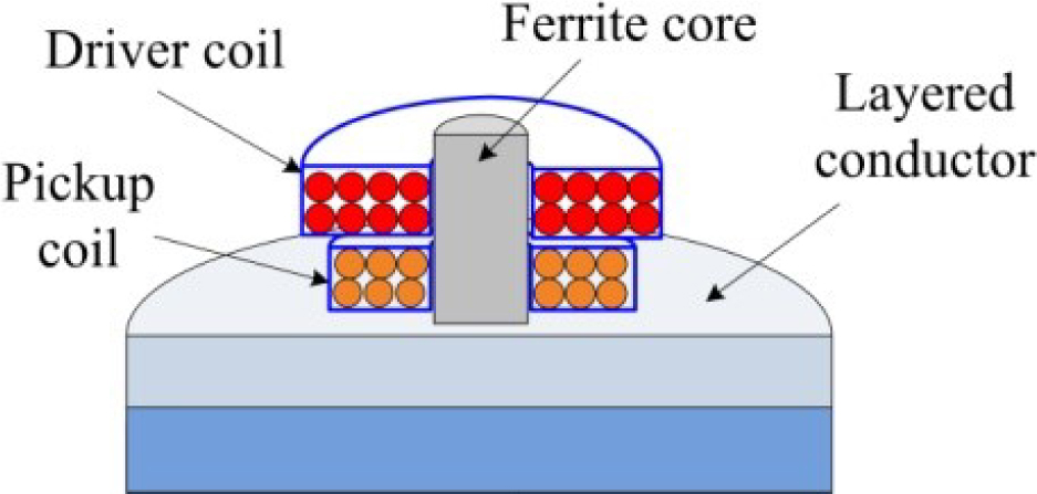
Figure 1: Cross-sectional view of a driver and a pick-up coils encircling an I-core above layered conductor.
II. SOLUTION
The geometry shown in Figure 2 (a) was analyzed first, where a sinusoidal current excited filamentary driver coil of radius r and a filamentary pickup coil of radius r encircle a ferrite cylinder with relative magnetic permeability . The probe is placed above a two-layer conductor with conductivities and respectively. The plane z = 0 coincides with the top surface of the conductor. The infinite solution domain is truncated by a cylindrical surface of radius b, and the whole problem geometry is divided into six regions along the axial direction.
Using the separation of variables method, the general form of the magnetic vector potential in all these regions can be written as a series of first kind Bessel functions of one order and solved with the boundary and interface conditions [13].
In Figure 2 (a), regions 1, 4, 5 and 6 contain only air or a conductor, the eigenvalues q are the positive real roots of the equation:
| (1) |
where N is the number of summation terms.
Because regions 2 and 3 comprise two sub-regions, the ferrite core and the air, so the radial dependence in the expressions for of these two sub-regions can be written as below.
For region 2:
| (2) | |||
| (3) |
where J and Y are first kind Bessel functions of n order, and p are the corresponding discrete eigenvalues.
In regions 2 and 3, by using the continuity of B and H on the interface r = a gives
| (4) | |||
| (5) |
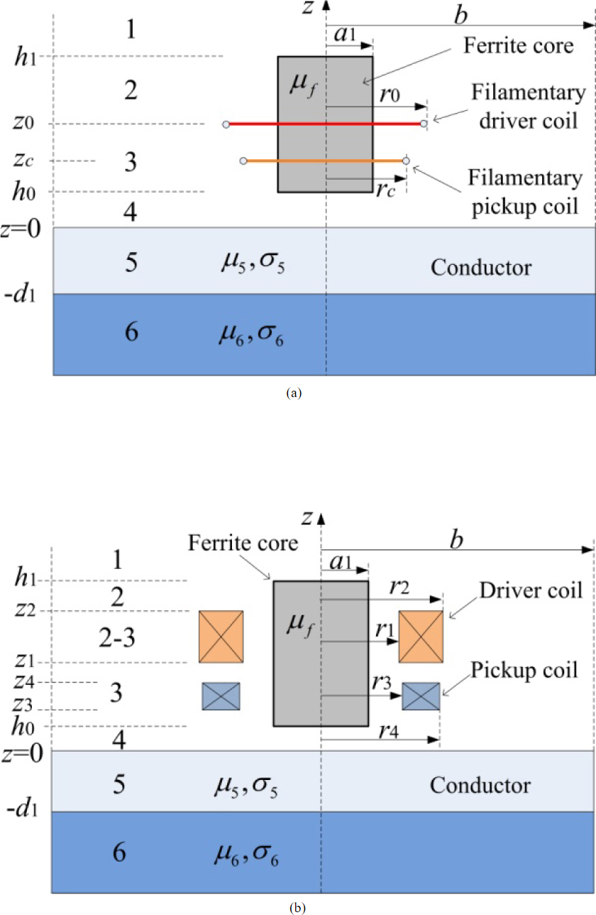
Figure 2: (a) Filamentary and (b) rectangular cross-section driver and pickup coils encircling an I-core above layered conductor.
Since at the boundary r = b, must also hold, the following equation is formed:
| (6) |
where
| (7) |
The eigenvalues p can be calculated using numerical procedures, such as FindRoot() in Mathematica or fzero() in Matlab to find real roots of eqn (6). Following the method of variables separation, the expressions for in various regions of the problem in Figure 2 (a) have the following forms, which are expressed in matrix notation:
| (8) | |||
| (9) | |||
| (10) | |||
| (11) | |||
| (12) | |||
| (13) |
where
| (14) | |||
| (15) |
In eqn (8)–(13), , , are row vectors; , , , and exponentials , , , are diagonal matrices. and are column vectors of unknown coefficients.
The interface conditions, continuity of B and H between the six regions of the problem have to be satisfied. These unknown coefficients and the discrete eigenvalues are to be determined from the boundary and interface conditions. The magnetic vector potential of region 3 in Figure 2 (a) excited by filamentarydriver coil is obtained:
| (16) |
By using superposition method, the magnetic vector potential in region 3 excited by rectangular cross-section coil with rectangular cross sectionshown in Figure 2 (b) can be derived:
| (17) | ||||
The markedasmathitalicz direction magnetic flux density B in region 3 excited by driver coil of N turns can be obtained as follows:
| (18) |
The magnetic flux penetrated through a filamentary pick-up coil with radius r can be expressed as
| (19) |
The magnetic flux penetrated through N turns of pick-up coil with rectangular cross section can be derived as:
| (20) |
The induced voltage in pick-up coil can be expressed as:
| (21) |
where
| (22) | ||
| (23) | ||
| (24) | ||
| (25) | ||
| (26) | ||
| (27) | ||
| (28) | ||
| (29) | ||
| (30) |
where j is imaginary unit, N and N are the number of turns in the driver and pickup coils respectively, is the permeability of vacuum, and I are the angular frequency and effective value of the excitation current. The negative sign in eqn (22) states that the direction of induced voltage in pickup coil is always such that it will opposite the change in flux which produced it. The matrices D, T and U are defined in [13].
III. SPECIAL CASES
The expression of voltage induced in the pick-up coil of an I-cored driver-pickup probe located above layered conductor has been derived and can be calculated with eqn (21). When the layered conductor is absent, the voltage induced in the pick-up coil is expressed as Vand can also be calculated with eqn (21) by setting =0 and =0. The change of induced voltage in pickup coil due to the conductor can be obtained as V=V-V.
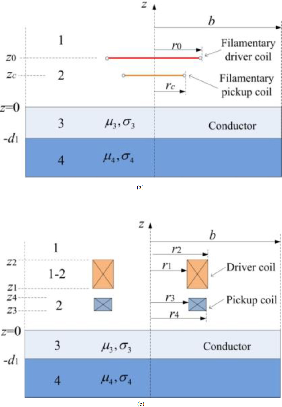
Figure 3: (a) Filamentary and (b) rectangular cross-section exciting and pick-up coil of air-core probe located above layered conductor.
When the I-core in Figure 2 was absent, the configuration changed into an air-cored probe with driver and pickup coils as shown in Figure 3. In this case, the expressions for in various regions of Figure 3 (a) have the following forms which are also given in the form of matrix:
| (31) | |||
| (32) | |||
| (33) | |||
| (34) |
where
| (35) | |||
| (36) |
is row vector; exponentials , , are diagonal matrices. and are column vectors of unknown coefficients.
Using same method as cored probe, the expression of induced voltage in the pick-up coil of an air-cored probe can be obtained as follow.
| (37) |
where
| (38) | ||
| (39) | ||
| (40) |
| (41) | ||
| (42) |
| (43) | ||
| (44) |
In the case where an air-cored driver-pickup coil probe is above layered conductor, when the conductor is absent, the induced voltage in pickup coil can also be calculated with eqn (37) by setting =0 and =0. The change of induced voltage in pickup coil due to conductor can also be obtained easily.
IV. EXPERIMENTAL VERIFICATION
The correctness of the proposed ferrite-cored driver-pickup probe model is verified by experimental measurements. The responses of pickup coil calculated by the model are compared with measured results. The experimental configuration is shown in Figure 4. The sinusoidal excitation signal of a frequency generated by a function generator is magnified by a power amplifier, and then transmitted to the driver coil. The amplitude of the sine wave and the magnification of the power amplifier are adjusted to ensure a 100 mA effective value current generated in the driver coil, the current was measured with a multimeter connected in series with the driver coil. Finally the voltage induced in the pickup coil is measured by a millivoltmeter parallel connection with the pickup coil. The responses of the induced voltage in the pickup coil are measured at different excitation frequencies range from 100 Hz to 30 kHz.
When the excitation frequency is fixed at 10 kHz, the responses of the pickup coil are also measured with different excitation currents.
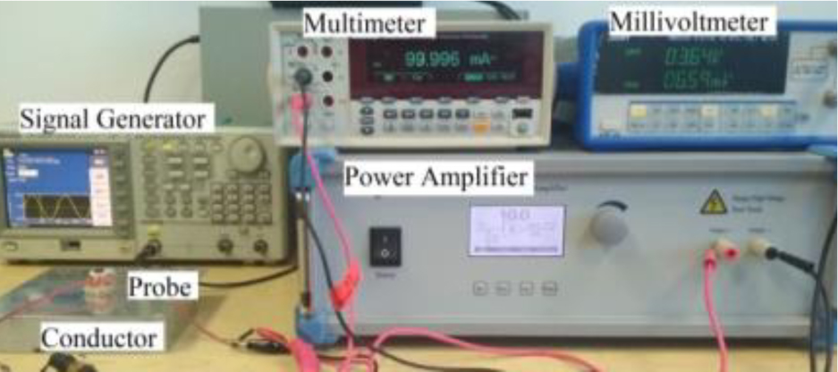
Figure 4: Experimental setup.
Table 1: Parameters of the coils, I-core, and conductor used in experiments and analytical calculation
| Inner radius | r | 5.2 mm |
|---|---|---|
| Outer radius | r | 7.2 mm |
| Parameter | z | 7.3 mm |
| Parameter | z | 16 mm |
| Number of turns | N | 430 |
| Inner radius | r | 5.1 mm |
| Outer radius | r | 7.8 mm |
| Parameter | z | 1.1 mm |
| Parameter | z | 5.1 mm |
| Number of turns | N | 150 |
| Core radius | a | 4 mm |
| Parameter | h | 18.1 mm |
| Relative permeability | 3500 | |
| Liftoff | h | 0.1 mm |
| Thickness | d | 2 mm |
| Relative permeability | ,,, | 1 |
| Conductivity | ,,, | 38 MS/m |
V. RESULTS AND DISCUSSION
The voltages induced in the pick-up coil of an I-cored driver-pickup probe and an air-cored driver-pickup probe located above layered conductor can be calculated by eqn (21) and (37) respectively using Matlab or Mathematica, the parameters used in analytical calculation are shown in Table 1, which are the same as those used in experiments.
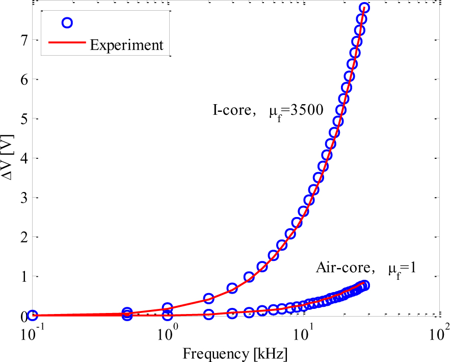
Figure 5: Induced voltage change of the pickup coil for an air-cored probe (= 1) and an I-cored probe (= 3500) as a function of frequency due to the conductor.
The calculated results are compared with the measurements. Figure 5 shows the induced voltage change of the pickup coil for an air-cored probe with = 1 and a ferrite-cored probe with = 3500, due to the layered conductor, as a function of frequency. The calculations are performed by setting the summation terms N= 60 and truncation radius b = 90 mm, more than ten times the outer radius of the pickup coil.
When keeping the exciting currents at 100 mA, the change of induced voltage in the pickup coil increases with frequency. Excited with same frequency, the I-cored probe obtained a larger voltage change than that of the air-cored probe. The analytical results agree with the experimental results very well.
The influence of the excitation current on the responses of the pickup coil is also examined with proposed analytical model, and the analytical results are compared with experiments. Figure 6 shows the induced voltage change of the pickup coil for an air-cored probe with = 1 and an I-cored probe with = 3500, as a function of excitation current, due to the layeredconductor.
When the excitation frequency is maintained at 10 kHz, the change of induced voltage in the pickup coil are calculated and measured at different excitation currents. The results are shown in Figure 6, the change of induced voltage in the pickup coil increases with the current. Excited with same current, the I-cored probe obtains a larger voltage change than that of the air-cored probe. The results of analytical calculation are in good agreement with the experiment. In all cases, the relative error between analytical calculation and experiment is less than 3%.
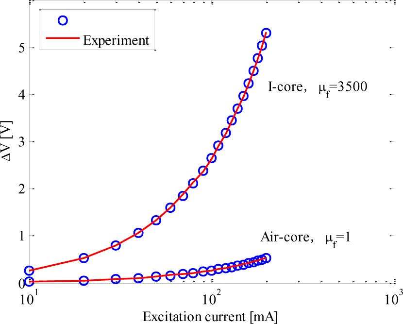
Figure 6: Induced voltage change of the pickup coil for an air-cored probe (= 1) and an I-cored probe (= 3500) as a function of excitation current due to the conductor.
VI. CONCLUSION
An analytical model of ferrite-cored probe containing a driver coil and a pickup coil located over layered conductor was presented. The expression of induced voltage in the pickup coil was derived. The change of induced voltage in pickup coil due to layered conductor was calculated and measured. The factors affecting the responses of pickup coil, such as the excitation frequency and excitation current in the driver coil were examined. The proposed analytical model can be used in simulation of eddy current testing, coating thickness measurement, or directly used in eddy current probe design.
REFERENCES
[1] G. Tytko and L. Dziczkowski, “Fast calculation of the filamentary coil impedance using the truncated region eigenfunction expansion method,” The Applied Computational Electromagnetics Society (ACES) Journal, vol. 33, no. 12, pp. 1461-1466, 2018.
[2] T. Theodoulidis and J. R. Bowler, “Impedance of a coil at an arbitrary position and orientation inside a conductive borehole or tube,” IEEE Trans. Magnetics, vol. 51, no. 4, pp. 1-6, 2015.
[3] C. V. Dodd and W. E. Deeds, “Analytical solutions to eddy-current probe-coil problems,” J. Appl. Phys., vol. 39, no. 6, pp. 2829-2838,1968.
[4] T. P. Theodoulidis and J. R. Bowler, “Bobbin coil signal variation due to an axisymmetric circumferential groove in a tube,” AIP Conf. Proc., vol. 1096, no. 1, pp. 1922-1929, 2009.
[5] S. R. Luis, G. S. Telmo, M. R. Pedro, V. Pedro, and M. Piedade, “A differential planar eddy currents probe: Fundamentals, modeling and experimental evaluation,” NDT E Int., vol. 51, pp. 85-93, 2012.
[6] T. P. Theodoulidis, “Developments in calculating the transient eddy-current response from a conductive plate,” IEEE Trans. Magnetics, vol. 44, no. 7, pp. 1894-1896, 2008.
[7] H. Huang and T. Takagi, “Inverse analyses for natural and multicracks using signals from a differential transmit-receive ECT probe,” IEEE Trans. Magnetics, vol. 38, no. 2, pp. 1009-1012, 2002.
[8] S. Zhang and N. Ida, “Analytical calculation of induced voltages of uniform eddy current probes above a moving conductor,” Lecture Notes Electr. Eng., vol. 506, pp. 177-193, 2019.
[9] S. K. Burke and M. E. Ibrahim, “Mutual impedance of air-cored coils above a conducting plate,” J. Phys. D: Appl. Phys., vol. 37, no. 13, pp. 1857-1868, 2004.
[10] D. R. Desjardins, T. W. Krause, A. Tetervak, and L. Clapham, “Concerning the derivation of exact solutions to inductive circuit problems for eddy current testing,” NDT E Int., vol. 68, pp. 128-135,2014.
[11] D. R. Desjardins, L. Clapham, and T. W. Krause, “Transient response of a driver-pickup coil probe in transient eddy current testing,” NDT E Int., vol. 75, pp. 8-14, 2015.
[12] S. Zhang, “An analytical model of a new T-cored coil used for eddy current nondestructive evaluation,” The Applied Computational Electromagnetics Society (ACES) Journal, vol. 35, no. 9, pp. 1099-1104, 2020.
[13] T. P. Theodoulidis, “Model of ferrite-cored probes for eddy current nondestructive evaluation,” J. Appl. Phys., vol. 93, no. 5, pp. 3071-3078,2003.
[14] S. Zhang, “Analytical model of an I-core coil for nondestructive evaluation of a conducting cylinder below an infinite plane conductor,” Meas. Sci. Rev., vol. 21, no. 4, pp. 99-105, 2021.
[15] S. Zhang, “Analytical model of a T-core coil above a multi-layer conductor with hidden hole using the TREE method for nondestructive evaluation,” COMPEL - Int. J. Comput. Math. Electr. Electron. Eng., vol. 40, no. 6, pp. 1104-1117,2021.
[16] G. Tytko and L. Dziczkowski, “E-cored coil with a circular air gap inside the core column used in eddy current testing,” IEEE Trans. Magnetics, vol. 51, no. 9, pp. 1-4, 2015.
[17] B. Wincheski, J. P. Fulton, S. Nath, M. Namkung, and J. W. Simpson, “Self-nulling eddy current probe for surface and subsurface flaw detection,” Mater. Eval., vol. 52, no. 1, pp. 22-26,1994.
[18] F. Jiang and S. Liu, “Calculation and analysis of an analytical model for magnetic field monitoring based on TREE in eddy current testing,” The Applied Computational Electromagnetics Society (ACES) Journal, vol. 33, no. 12, pp. 1489-1497, 2018.
[19] T. P. Theodoulidis and E. E. Kriezis, “Series expansions in eddy current nondestructive evaluation models,” J. Mater. Process. Technol., vol. 161, no. 1-2, pp. 343-347, 2005.
[20] F. Sakkaki and H. Bayani, “Solution to the problem of E-cored coil above a layered half-space using the method of truncated region eigenfunction expansion,” J. Appl. Phys., vol. 111, no. 7, pp. 2829-2864, 2012.
BIOGRAPHIES

Siquan Zhang received the Ph.D. degree in Material Processing Engineering from the South China University of Technology, Guangzhou, China. His current research interests include eddy current testing, analytical model in Non-destructive testing.

Chengkai Ye received the B.S. degree from Shanghai Maritime University. He is currently working towards the M.S. degree in Control Theory and Control Engineering. His current research interests include eddy current testing and the application of finite element method in NDT.
ACES JOURNAL, Vol. 37, No. 5, 632–638.
doi: 10.13052/2022.ACES.J.370513
© 2021 River Publishers