A Highly Compact Sext-band Bandpass Filter with Simple Structure and Wide Bandwidth
Lei Bai, Yiqi Zhuang and Zhibin Zeng
School of Microelectronics, Xidian University, Xi’an, 710071, China
bl-cherry@163.com, yqzhuang@xidian.edu.cn, zbzeng@163.com
Submitted On: December 22, 2021; Accepted On: October 17, 2022
ABSTRACT
A highly compact sext-band bandpass filter (BPF) is investigated in this paper, which adopts quad-section stepped impedance resonators (SIRs) along with a series of multiple open stubs. This quad-section SIRs are constructed by tri-section SIR loaded L-shaped resonator. To achieve compact size, the filter utilizes tri-section SIR and is embedded in the double L-shaped resonators. A series of multiple open stubs are introduced to improve fractional bandwidth and the return loss. A sext-band BPF centering at 1.12, 2.12, 2.78, 5.59, 6.59 and 8.97 GHz has been designed and fabricated. This highly compact sext-band with wide bandwidth and simple structure is constructed on Rogers 4350 with a dielectric constant of 3.66 and a height of 0.508 mm. The overall size of the fabricated filter is . Good agreements are observed between the simulated and measured results.
Index Terms: bandpass filter, open stubs, quad-section stepped impedance resonator(SIR), sext-band.
I. INTRODUCTION
Modern communication systems operate in multiple frequency bands to accommodate different applications, such as global positioning system (GPS), wireless local area network (WLAN), global system for mobile communication (GSM), long term evolution (LTE) channels, C-band satellite communication services (CSCS) and X-band satellite communication services (XSCS) [1]. Multiband bandpass filter (BPF), an indispensable component, is increasingly attracting the attention of design engineers and has been extensively studied in recent years. For designing multiband BPFs, multiple sets of resonators are employed [2, 3]. In [4], a multi-band BPF was designed, which combined a low-pass filter (LPF) with two open stub-loaded shorted stubs. Another tri-band BPF employed two pairs of the open-loop uniform impedance resonators (OLUIRs) with simple structure [5], the circuit size is , it occupied a considerable large circuit size. Furthermore, more and more designers pay attention to designing multi-band BPF with more passbands. In [6], a high-selectivity quint-band BPF was constructed based on five tri-mode stub-load stepped-impedance resonators (SIR). Resonators of non-ideal sizes, numbering six or more, have been used for designing sext-band BPF [7] and a sept-band [8] BPFs. To reduce the number of resonators, multi-mode resonators (MMRs) [9]–[11] are frequently employed. The commonly used structures for multi-mode resonators are stub-loaded resonators [12, 13], stepped-impedance resonators [9, 12, 14] and ring resonator [15]. In [14], a quint-wideband BPF was presented, it adopted spiral and open-loop coupled structures with mixed electric and magnetic coupling (MEMC) to reduce design complexity, but the circuit size was relatively large. Sext-band BPFs utilizing cascading stages of SIRs and SIR-loaded tapered lines were reported in [16] and [17]. Although the number of resonators was reduced, the size was relatively large, and the return loss was poor. To realize multiple passbands, multiple modes and transmission zeros (TZs) are used. A single MMR with sept-band characteristics was presented in [18]. In [19], a wideband octa-band BPF was poposed, it utlilized a lowpass filter (LPF) loaded shotted stubs. However these sept-/octa-band BPF adopts one or more via holes. These above reported filters are either complex in structure (multiple via holes or multilayer), large in size or narrow in bandwidth. Therefore, the design of multi-band BPF with simple structure, compact size, and wide fractional bandwidth is a great challenge. In this paper, a highly compact sext-band BPF with compact size, wide bandwidth, and simple structure is presented. This filter adopts quad-section SIRs and multiple open stubs. Owing to the reduction of coupling section, a sext-band BPF design procedure is simple. The designed filter is analyzed by the full-wave electromagnetic (EM) simulation software HFSS. It is fabricated and measured using E5071C to verify the simulated results. The rest of this paper is organized as follow. In section II, the design of sext band filter is detailed and highlighted, which is composed three parts, including analysis of quad-section SIRs, optimization of the quad-section SIRs and filter configuration. The simulated and measured results are prsented in section III The conclusion of this paper is drawn in section IV. The proposed filter has a simple structure, a miniature size and a wide bandwidth simultaneously. The passbands generated by the proposed BPF are suitable for GPS, WLAN, and XCSC communications and so on.

Figure 1: Schematic of quad-section SIRs and equivalent circuit of quad-section SIRs. (a) quad-section SIRs. (b) Equivalent transmission line model of quad-section SIRs.

Figure 2: Basic odd-and even-mode equivalent circuit of quad-section SIRs.
II. DESIGN OF SEXT-BAND FILTER
A. Analysis of quad-section SIRs
Figure 1 (a) shows the geometry of the quad-section SIRs, which utilize two tri-section SIRs along with L-shaped resonator, so it is defined quad-section SIRs. Among which, resonator I and resonator II are coupled through the coupling gap. The width of the coupling gap is denoted by d. According to Fig. 1 (a), since the structure has a high degree of symmetry and can be seen as four identical parts, we only analyzed the transmission line model for one quarter of the structure (along the direction of the green arrow in Fig. 1 (a), i.e., the triangular AOB). The equivalent transmission line model is given in Fig. 1 (b). The characteristic admittances are Y, Y, Y, and Y, respectively, where Y is the folded part consisting of (L, W) and (L, W). The corresponding electrical lengths are , , , and , respectively. The admittance ratios for the four different admittance are related through K, K and K, where K = Y/Y, K = Y/Y, K = Y/Y. Since the quad-section SIRs are symmetrical in structure, the odd-even-mode method is applied for its analysis and the relevant equivalent circuit is shown in Fig. 2 [20]. The input admittance of the odd-mode and even-mode excitation can be derived as follows.
Odd-mode:
| (1) |
where
| (2) |
| (3) |
Even-mode:
| (4) |
where
| (5) |
| (6) |
for simplicity, assuming = = = = . By imposing the resonance conditions, the resonance conditions and = 0, the resonance frequencies of the odd-mode and the even-mode are determined by the respective equation:
| (7) | |
| (8) | |
from Equation (7) and (8), the center frequency for each passband is simply chosen by adjusting the impedance ratio K, K, and K. The variation of the frequency ratios as a function of the admittance ratios K, K, and K is shown in Fig. 3. It is pre-selected that the width of the line section (W) having the characteristic admittance Y to be 1 mm (which corresponds to 52.3 ). In Fig. 3 (a), when K and K are fixed, f/f, f/f and f/f remain almost unchanged. The f/f slightly reduces and f/f greatly increases. When K and K have been fixed, f/f, f/f are almost unchanged, the f/f decreases, the f/f and f/f dramatically decreases (see Fig. 3 (b)). f/f, f/f and f/f are almost unchanged while f/f and f/f gradually increase in Fig. 3 (c). Therefore, by appropriately adjusting the quad-section SIRs, a basic multiple bands could be obtained at desired frequencies. Finally, the admittance ratios are calculated as K = 1.4, K = 0.7 and K= 1.2. Choosing characteristic impedance Z = 63.7 , Z = 52.3 , Z = 75.0 and Z = 52.3 .
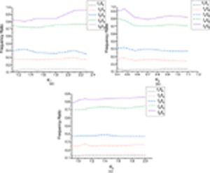
Figure 3: Frequency characteristics of the proposed quad-section SIRs with varied admittance ratios.
B. Optimization of the quad-section SIRs
Based on the analysis above, the quad-section SIRs can generate the desired frequency bands. The dimensions of the quad-section SIRs (see Fig. 1 a)) are chosen as (all in mm): L = 3.5, L = 5.7, L = 13.1, L = 22, L = 4.1, W = 0.7, W = 1, W = 0.5, W = 1, W = 0.7. As shown in Fig. 4, when multiple open stubs are not loaded, the center frequencies of the quad-section SIRs are at 1.08, 2.12, 2.99, 3.87, 5.77, 6.53, and 7.9 GHz. It should be noted that the forth band is a false band with narrow bandwidth (see Fig. 4 black line). Since the length of the open stub can affect the resonant frequency, when the stub length is longer, the resonant frequency is lower [21]. To merge the false band with other frequency, multiple open stubs are introduced. A series of multiple open stubs are symmetrically loaded on L-shaped. From Fig. 4, with multiple open stubs, the center frequencies are at 0.98, 1.92, 2.79, 5.13, 6.42, and 7.74 GHz. Furthermore, loading open stubs can increase the bandwidth and improve the return loss. Their 3-dB fractional bandwidth are 19.4, 26.4, 26, 3.6, 18, 8.4, and 11.9 without open stubs, but the fractional bandwidth are 17.3, 27.1, 28.3, 21.6, 15.3, and 13 with open stubs, respectively. In addition, the first passband characteristic is better than the quad-section SIRs. The return loss of fifth and sixth bands are also clearly superior to the former.The return loss up to 31.01 dB after loading multiple open stubs in fifth passband compares to 13.75 dB before loading. The return loss in sixth passband are 15.49 dB and 11.76 dB, respectively.
Figure 5 shows the S-parameter varies from coupling gap. The first three center frequencies are constant, the sixth band slightly change and the forth and fifth bands obviously change. It can be obtained from Fig. 5 (a) that with the coupling gap from 0.075 to 0.125 mm, the forth and fifth bands from 5.03 to 5.49 GHz, from 6.08 to 6.4 GHz, respectively. When d from 0.075 to 0.125 mm, the return loss of the fifith passband can reach -30 dB. Furthermore, the minimal variation in insertion loss between fifth and sixth passband is shown in Fig. 5 (b). Finally, the proposed sext-band BPF is constructed by the quad-section SIRs and multiple open stubs, which is easy to build. Consequently, a sext-band with simple structure and wide fractional bandwidth is obtained. Additionally, the designed BPF has only two resonators and one coupling gap.
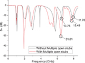
Figure 4: The simulated S of the quad-section SIRs and loaded multiple stubs.
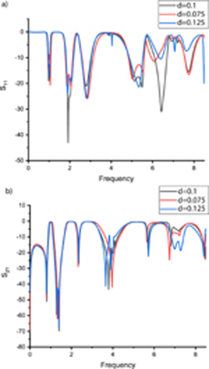
Figure 5: The simulated S-parameters (S and S) of coupling gap.

Figure 6: Layout of designed sext-band BPF.
C. Filter Configuration
To verify the practicability of the proposed quad-section SIRs, a sext-band BPF, adopting quad-section SIRs along with a series of multiple open stubs is designed. The geometric configuration is shown in Fig. 6. In quad-section SIRs, double L-shaped resonators are symmetrically distributed on the outside and coupled into as quare structure, while the tri-section SIRs are embedded inside and loaded in the double L-shaped resonator. The quad-section SIRs can generate the desired passbands. In addition, a series of multiple open stubs are loaded on the L-shape resonators. These multiple open stubs are introduced to improve the bandwidth and return loss. In a multi-band BPF, the coupling is a significant factor that can increase the insertion loss and the return loss. Compared with other multi-band BPFs, the proposed BPF has only two resonators (Resnoator I and Resonator II) and no via hole that can greatly reduces its complexity and fabricated cost [14].
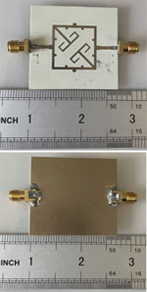
Figure 7: Photograph of the proposed sext-band BPF.
III. SIMULATED AND MEASURED RESULTS
The proposed sext-band BPF is fabricated on a 0.508 mm thick Rogers RO4350 substrate with a dielectric constant of 3.66 and a loss tangent of 0.004. Figure 7 shows the photograph of fabricatred filter. The dimensions of the design optimized utilizing the Ansoft HFSS 15.0 are (millimeters): L = 2, L = 3.5, L = 5.7, L = 13.1, L = 22, L = 4.1, L = 1.6, L = 6.5, L = 6.5, L = 7, L = 7, L = 2, W = 1.5, W = 2.6, W = 0.7, W = 1, W = 0.5, W = 1, W = 0.7, W = 2.2, W = 1, d = 0.1. Simulated and measured results of the designed filter are shown in Fig. 8. The measured centre frequencies are located at 1.12, 2.12, 2.78, 5.59, 6.59, and 7.97 GHz. Their 3-dB fractional bandwidths are 12.5, 26.4, 27.0, 15.4, 10.5, and 9.8 , respectively. The filter return losses are 11.5, 35.8, 19.5, 30.4, 36.1, and 13.5 dB. The filter size is , which amounts to , where is the guided wavelength on the substrate at the center of the first passband. The minor difference between the simulated and the measured results is due to production deficiency, connector losses and imperfection of the substrate.
The performance of the proposed sext-band is compared with other works, and a summary is given in Table 1. From Table 1, as in the literature [7, 16, 17], the filter proposed in this paper also generates 6 passbands, but has a wider fractional bandwidth. For example, all bandwidths in this paper are more than 10 higher than the corresponding bandwidths in the literature [7]. The fractional bandwidth also reaches 26.4, which is much higher than the bandwidth of the second band in the other two literature. Moreover, the size of the proposed filters were reduced by 16.7 and 29.4, respectively, compared to the literature [16, 17]. Compared to the literature [18], the presented work has a wider bandwidth even though their circuit sizes are approximately the same. Table 2 summarizes the comparison between the proposed filter and the recently proposed couterparts designed structure. The filter design proposed in this paper is simple, has low manufacturing cost, but is still able to produce more passbands while using fewer resonators and no via holes.
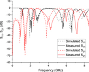
Figure 8: Simulated and measured results.
Table 1: Comparisons with the other multi-band BPFs
| Ref | CFs(GHz)/FBW() | Size () | |
|---|---|---|---|
| [7] | 3.55 | 0.9/1.5 | 1.2/1.3 |
| 1.4/1.4 | 1.7/1.3 | 2/1.5 | 2.4/1.4 |
| [16] | 3.66 | .56/17.9 | |
| 3.17/13.2 | 4.68/29 | 6.02/7.14 | 8.21/8.04 |
| 9.06/7.28 | [17] | 3.5 | |
| 1.7/19.4 | 3.48/9.2 | 5.08/30 | 6.5/6.7 |
| 8.66/10.2 | 10.18/13 | [18] | |
| 2.2 | 1/13 | 1.6/10.2 | 2.3/15.9 |
| 2.8/6.8 | 3.5/9.4 | 4.2/3 | 5/4.6 |
| This work | 3.66 | 1.12/12.5 | |
| 2.12/26.4 | 2.78/27 | 5.59/15.4 | 6.59/10.5 |
| 7.97/9.8 |
Table 2: Comparisons with the other multi-band BPFs
| Ref | NR | NB | Structure | Via Hole |
|---|---|---|---|---|
| [7] | 6 | 6 | SIRs | 6 via hole |
| [8] | 8 | 7 | SL-SIR | 4 via hole |
| [10] | 2 | 5 | MMR+open stubs | none |
| [18] | 1 | 7 | a single MMR | 5 via hole |
| [19] | NA | 8 | short stubs+LPF | 1 via hole |
| This work | 2 | 6 | quad-section SIRs+open stubs | none |
NA = not available; NR = number of resonators
NB = number of passbands
IV. CONCLUSION
This letter proposed a sext-band BPF aimed at large fractional bandwidth, highly compact size, and simple structure. The designed BPF adopts quad-section SIRs along with multiple open stubs, The quad-section SIRs utilize two tri-section stepped impedance resonators loaded double L-shaped resonators to achieve enough multi-band, and a series of multiple open stubs loaded double L-shaped resonators are added to improve the fractional bandwidth and return loss. The fabricated sext-band BPF’s center frequencies are at 1.12, 2.12, 2.78, 5.59, 6.59, and 7.97 GHz. This makes it suitable for GPS, WLAN, CSCS and XSCS applications. Owing to these merits, it becomes a good choice for achieving sext-band bandpass characteristics.
ACKNOWLEDGMENTS
This work was supported in part by the National Natural Science Foundation of Shaanxi Province under Grant NO.2019KW-057 and 111 project.
REFERENCES
[1] Y. Zhang, L. Gao, and X. Y. Zhang, “Compact quad-band bandpass filter for DCS/WLAN/WiMAX/5G Wi-Fi application,” IEEE Microwave Wireless Component Letter, vol. 25, no. 10, pp. 645-647, Aug. 2015
[2] Y. Wu, L. Cui, Z. Zheng, W. Wang, and Y. Liu, “A simple planar dual-band bandpass filter with multiple transmission Poles and zeros,” Circuits and Systems II: Express Briefs, vol. 65, no. 1, pp. 56-60, Jan. 2018.
[3] R. Gomez-Garcia, R. Loeches-Sanchez, D. Psychogiou, and D. Peroulis, “Multi-stub-loaded differential-mode planar multiband bandpass filters,” Circuits and Systems II: Express Briefs, vol. 65, no. 3, pp. 271-275, Mar. 2018.
[4] Q. Yang, Y.-C. Jiao, and Z. Zhang, “Compact multiband bandpass filter using low-pass filter combined with open stub-loaded shorted stub,” IEEE Transactions on Microwave Theory and Techniques, vol. 66, no. 4, pp. 1926-1938, Apr. 2018.
[5] M.-H. Weng, C.-W. Hsu, Y. Lin, C.-Y. Tsai, and R.-Y. Yang, “A simple method to design a tri-bandpass filter using open-loop uniform impedance resonators,” Journal of Electromagnetic Waves and Applications, vol. 34, no. 1, pp. 103-115, Nov. 2019.
[6] C.-F. Chen, “Design of a compact microstrip quint-band filter based on the tri-mode stub-loaded stepped-impedance resonators,” IEEE Microwave and Wireless Components Letters , vol. 22, no. 7, pp. 357-359, Jul. 2012.
[7] K.-W. Hsu, J.-H. Lin, and W.-H. Tu, “Compact sext-band bandpass filter with sharp rejection response,” IEEE Microwave and Wireless Components Letters, vol. 24, no. 9, pp. 593-595, Sep. 2014.
[8] C.-F. Chen, S.-F. Chang, and B.-H. Tseng, “Design of compact microstrip sept-band bandpass filter with flexible passband allocation,” IEEE Microwave and Wireless Components Letters, vol. 24, no. 9, pp. 346-348, May 2016.
[9] D. Bukuru, K. Song, F. Zhang, Y. Zhu, and M. Fan, “Compact quad-band bandpass filter using quad-mode stepped impedance resonator and multiple coupling circuits,” IEEE Transactions on Microwave Theory and Techniques, vol. 65, no. 3, pp. 783-791, Mar. 2017.
[10] X. Li, Y. Zhang, X. Zhang, L. Qu, and Y. Fan, “Compact quint-band Bandpass Filter design in a rigorous manner utilizing multimode stub-loaded taper,” Microwave and Optical Technology Letters, vol. 60, no. 5, pp. 1230-1234, May 2018.
[11] B.-H. Zhu, Z. Wang, E. Kim, and N. Kim, “A quad-band bandpass filter using sept-mode double square-ring loaded resonator,” Microwave and Optical Technology Letters, vol. 62, no. 5, pp. 1906-1913, May 2020.
[12] F. Wei, P.-Y. Qin, Y. Jay Guo, and X.-W. Shi, “Design of multi-band bandpass filters based on stub loaded stepped-impedance resonator with defected microstrip structure,” IET Microwaves, Antennas and Propagation, vol. 10, no. 2, pp. 230-236, Jan. 2016.
[13] X. Kai-Da and Z. Fengyu, “High selectivity bandpass filter using three pairs of coupled lines loaded with shorted stubs,” Applied Computational Electromagnetics Society (ACES) Journal, vol. 34, no. 10, pp.469-474, 2019.
[14] I. A. Yasir, Y. Tu, O.-P. Naser, I. T. E. Elfergani, A.-A. Raed, R. Jonathan, and J. M. Noras, “Mixed-coupling multi-function quint-wideband asymmetric stepped impedance resonator filter,” Microwave and Optical Technology Letters, vol. 61, no. 5, pp. 1181-1184, May 2019.
[15] D. K. Choudhary and R. K. Chaudhary, “Miniaturized quad-band filter with improved selectivity using split ring resonators and metallic strips,” International Journal of RF and Microwave Computer-Aided Engineering, vol. 31, no. 10, pp. 1-9, Oct. 2021.
[16] X. Li, Y. Zhang, Y. Tang, J. Xu, and Y. Fan, “Sext‐band bandpass filter with compactness based on cascading stage of SIRs,” Microwave and Optical Technology Letters, vol. 60, no. 2, pp. 306-310, Feb. 2018.
[17] X. Li, Y. Zhang, Y. Tian, Y. Yang, and Y. Fan, “Quad-and sext-band bandpass filter based on multimode resonator utilizing SIRs-loaded tapered-line,” Microwave and Optical Technology Letters, vol. 60, no. 2, pp. 650-654, Feb. 2018.
[18] X. Bi, L. Wang, Q. Ma, B. Hu and Q. Xu, “A compact sept-band bandpass filter utilising a single multi-mode resonator” IET Microwaves, Antennas and Propagation, vol. 13, no. 12, pp. 2013-2019, 2019.
[19] Q. Yang, S. Liu, K.-D. Xu, and A. Zhang,“Compact octa-band bandpass filter based on controllable transmission zeros with wide upper stopband,” Applied Computational Electromagnetics Society (ACES) Journal, vol. 36, no. 9, pp. 1159-1163, Sep. 2021.
[20] J. Wang, S. He, F. You, W. Shi, J. Peng, and C. Li, “Codesign of high-efficiency power amplifier and ring-resonator filter based on a series of continuous modes and even–odd-mode analysis,” IEEE Transactions on Microwave Theory and Techniques, vol. 66, no. 6, pp.2867-1878, Jun. 2018.
[21] J. Chen, J.-Z. Chen, B. Wu, Y. L. Zhang, and C.-H. Liang, “Design of triple-band microstrip filter with transmission zeros using open stubs,” Journal of Electromagnetic Waves and Applications, vol. 26, no. 4, pp. 525-534, Apr. 2012.
BIOGRAPHIES

Lei Bai received his Masters Degree in Signal and Information Processing from Xi’an University of Technology in 2012. He is currently a doctor at school of microelectronics, Xidian University, His research interests include passive filter design, high-speed integrated circuits, etc.

Yiqi Zhuang received the Ph.D. from Xidian University in 1995. He is the director of the National Integrated Circuit Talents Training Base, professor and doctoral supervisor. His current research interests include communication and power system integration, short-distance wireless communication, microelectronic device noise and reliability application technology, etc.

Zhibin Zeng received the Ph.D. from Xidian University. He has completed the design of wireless Bluetooth system, wireless WIFI system and analysis of signal integrity. He has published more than 10 articles on EI and SCI, and applied for more than 10 patents. His research interests include high-speed circuit design, embedded systems and analysis of signal integrity.
ACES JOURNAL, Vol. 37, No. 10, 1089–1095
doi: 10.13052/2022.ACES.J.371009
© 2022 River Publishers