Calculation and Characteristics Analysis for Radiated Electromagnetic Field of High Voltage Converter Valve
Hongsen Zou, Lin Zheng, Yuan Zhang, Jianan Zhang, Yajie Wang, and Huafeng Wang
1State Grid Ningxia Electric Power CO., LTD. Ultrahigh Voltage Company
hs-zou@qq.com, 18408673777@163.com
2State Key Laboratory of Advanced Power Transmission Technology
(State Grid Smart Grid Research Institute CO., LTD.)
3School of Telecommunication Engineering
Xidian University, Xi’an 710071, China
zhenglin@geiri.sgcc.com.cn, zjnde@126.com, wangyajie@geiri.sgcc.com.cn, wanghuafeng@geiri.sgcc.com.cn
Submitted On: December 28, 2021; Accepted On: May 29, 2022
Abstract
Calculation and analysis of the radiated electromagnetic field by the high voltage converter valve are very important for the electromagnetic compatibility analysis between the various components of the converter system. First, the electromagnetic radiation calculation process of the converter valve is proposed. Then, according to the actual engineering application, a DC transmission simulation system of the converter system was built, and the current of the converter valve tower arm was obtained. Subsequently, according to the actual size, a 3D calculation model of the converter valve tower was established, and an MoM-based calculation method for the electromagnetic field of the converter valve tower was proposed. Finally, the attenuation characteristics and azimuth characteristics of the converter valve tower are analyzed, and the distribution rules of the radiated electromagnetic field inside the high voltage converter valve hall are clarified, which provide a theoretical foundation for the evaluation of the electromagnetic compatibility of the converter system.
Index Terms: A 3D calculation model, converter valve, DC transmission simulation system, MoM, radiated electromagnetic field.
I. INTRODUCTION
High voltage direct current (HVDC) transmission has become the best choice for power transmission due to its large transmission capacity, long transmission distance, and high stability [1]. Among them, the HVDC transmission grid can not only realize large-scale and long-distance transmission of electric energy but also can greatly improve the safety, reliability, flexibility, and economy of the grid, and it has significant social and economic benefits. HVDC transmission technology is the new peak of direct current (DC) transmission technology in the world, and it will play an irreplaceable role in long-distance power transmission projects [2].
The converter station is the center of AC and DC power exchange. It realizes the energy transfer from the AC system to the DC system [3]. It is the core of HVDC transmission technology. Its operation status directly affects the safety and stability of the entire DC transmission system and even the AC system. However, in the converter valve hall, the switching transient of the converter valve will generate a broadband current inside the valve tower, thereby deteriorating the surrounding electromagnetic environment [4]. At the same time, the online monitoring unit, communication system, and protection and control system of the converter valve are very close to the valve hall and are in a strong electromagnetic radiation field, which seriously affects its normal operation [5]. For this reason, it is necessary to carry out the calculation of the electromagnetic radiation of the converter valve and the research its attenuation characteristics.
In 1971, Harrold conducted experimental research, analyzed the frequency of power line radiofrequency electromagnetic noise, and used a spectrum analyzer to analyze the interference characteristics of radio frequency (RF) noise [5]. Afterward, Annestrand studied the radio interference generated when the converter valve was turned on [6], analyzed the factors affecting the level of radio interference, and proposed corresponding suppression methods. Maruvada and Gilsing proposed a calculation method for analyzing and calculating the RF interference level of converter stations, which was verified based on the Vancouver Island converter station [7]. Morse measured the electromagnetic interference of the Nelson River DC transmission line in Canada [8, 9]. Melvolil et al. analyzed the electromagnetic noise voltage within the carrier frequency range of the HVDC converter station [10]. Bacon et al. measured the electromagnetic noise of AC lines near HVDC transmission lines. The measurement results are helpful to analyze the interference propagation mechanism between AC and DC transmission lines [11]. The International Special Committee on Radio Interference proposed a calculation formula suitable for the calculation and analysis of the radio interference of the bipolar DC line based on the large amount of measurement data obtained by the test line and the actual line in operation [12]. In addition, funded by the Canadian Electric Power Association, Maruvada, Malewki, Wong, etc., carried out electromagnetic disturbance measurements on two 400-kV converter stations in Canada and gave the electromagnetic field inside the station and 500 m outside the station 0.1. Measurement results of radio interference and RF interference in the M-5MHz frequency band [15]. Tatro and others in New England analyzed in detail the power carrier problem of a 450-kV, 1800-MW converter station through measurement and calculation [16]. Japanese Yuichirou Murata and Shinji Tanabe used the method of moments to calculate the RF noise generated by the transmission line of the HVDC converter station and produced a 400:1 scaling model. The measurement results are in good agreement with the calculation results [17]. With the development of HVDC transmission technology, the issue of electromagnetic compatibility in converter stations has been paid more attention, but almost all research works are concentrated in the field of RF interference, and research works are conducted on the basis of experiments.
To this end, this paper proposes a calculation method for the electromagnetic disturbance radiated by the high-pressure converter valve and analyzes the frequency characteristics and attenuation characteristics of the electromagnetic disturbance radiated by the high-pressure converter valve to provide theoretical guidance for the electromagnetic compatibility design of the high-pressure converter system.
II. CALCULATION METHOD
A Calculation process of radiated electromagnetic field of converter valve
For the analysis of the electromagnetic radiation level of the valve of the flexible DC converter station, it is necessary to first obtain the current of all the wires at any moment by measurement or calculation; then for the spatial point where the electromagnetic field strength needs to be calculated, calculate the field strength of each section of current at the same moment at this point and superimpose. Combined with the existing commonly used calculation software FEKO belongs to the characteristics of the frequency domain method, the time domain current obtained in the first step needs to be Fourier transformed to obtain its frequency domain response, and then calculate the response at different frequency points in the space point and superimposed to obtain the electric field strength at any point in space. The specific calculation steps are as follows.
The establishment of the 3D model of the valve tower. For 3D models of components without current inflow, such as shields, metal scatterers are modeled according to the actual dimensions. For 3D models of components with current flow, such as the convertor valve unit and its internal power modules, a simplified unit model is built using a metal plate instead of the power units, considering the electrical connection of each power module inside the unit.
Setting of the excitation source. The excitation source is in the form of a single current source at the point of connection to the DC bus with the excitation source injected from one end and withdrawn from the other.
The calculation area is designated. Through the setting of boundary conditions, calculate the radiation field generated by the single excitation source considering the case of metal scatterers in the valve hall.
The calculation of valve tower electromagnetic radiation. The DC bus current obtained from the PSCAD calculation is Fourier transformed to obtain the amplitude-frequency characteristics at different frequencies. The frequency points of interest are multiplied with the radiation field results obtained in step (4) to obtain the electromagnetic radiation of the valve tower.
B Radiation source analysis of converter valve hall
From the generation mechanism distinction, the flexible DC converter valve electromagnetic disturbance sources can be divided into the following three kinds: (1) the operation of the converter valve caused by continuous electromagnetic disturbance; (2) the converter station high-voltage equipment corona generated electromagnetic disturbance; (3) the converter station high-voltage equipment discharge generated electromagnetic disturbance. Among them, corona and interference generated by the discharge of equipment are similar to the general AC high-voltage field station interference phenomenon. A basic assumption of the study converter station design can meet the immunity requirements corresponding to this phenomenon. In the occurrence of the above phenomenon, it can be ensured that the converter station equipment is not affected and is a normal operation; so the analysis in this paper is no longer considered.
Establish a DC transmission commutation simulation system in actual engineering applications, as shown in Figure 1.
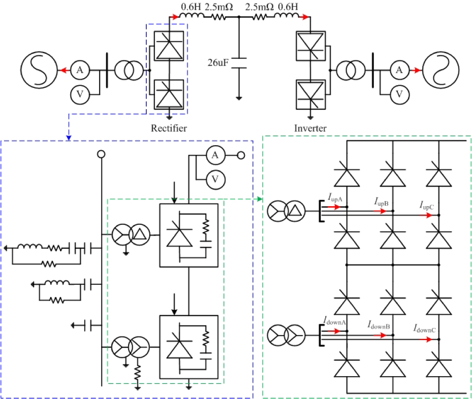
Figure 1: The commutation simulation system of DC transmission.
This paper mainly analyzes the electromagnetic radiation disturbance of the converter valve hall on the rectifier side, and the pulse current of the upper and lower three-phase bridge arms is shown in Figure 2(a). Furthermore, the frequency domain analysis method is used to obtain the amplitude-frequency characteristics of the bridge arm current, as shown in Figure 2(b). It can be seen that the currents of the three phases all exhibit periodic square-wave characteristics in the time domain, and only small differences appear in the high-frequency band in the frequency domain. In the third step calculation, the single radiation field is usually multiplied by the envelope parameter.
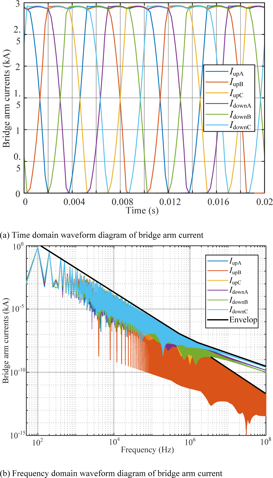
Figure 2: Time-frequency parameters of three-phase bridge arm current.
To facilitate the accuracy of the calculation of the radiated electromagnetic field, the amplitude-frequency envelope is used as the disturbance source, and the current excitation source is set at the corresponding bridge arm position.
C 3D models and calculation method of converter valve tower
Due to the existence of valve towers and a large number of metal conductor structures such as pole conductors in the valve hall, while the converter valve reflects different impedance characteristics under different operating conditions and frequencies, only the use of electromagnetic field numerical calculation methods to solve such complex electromagnetic field problems more accurately. In this paper, FEKO, a numerical calculation software developed based on the method of moments, is used to model and calculate in the valve hall.
For the electric field bold italicE, the expression is
| (1) |
To solve for the currentbold italic J, a triangular section is made of the metal surface, as shown in Figure 3. After the triangular section, each side of the triangle is numbered and the positive and negative numbers of the two triangles connected to the side are defined.
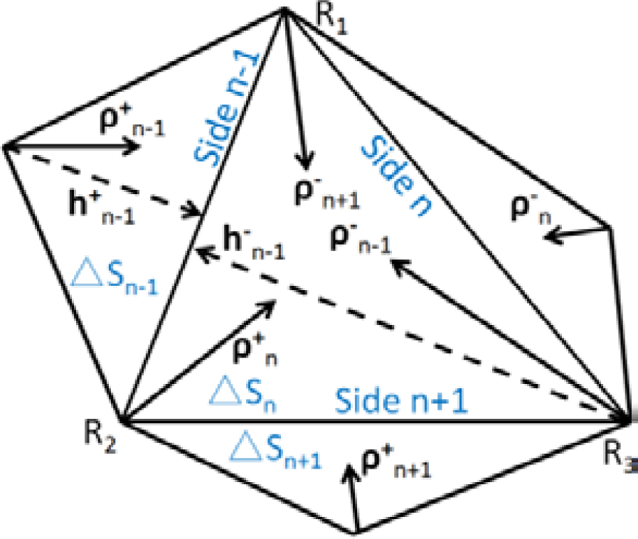
Figure 3: Definition of the parameters of a triangular surface element.
Introduce the current basis function as
| (2) |
where denotes the distance from the vertex corresponding to the n-1th edge to the n-1th edge, and denotes the vector from the vertex within S corresponding to the nth edge to the field point within triangle S. denotes the vector from the vertex of the other triangle corresponding to the nth edge to the field point.
The current bold italicJ at any point in the triangle can be expanded by the vector from that point to the three vertices
| (3) |
Therefore, the electric field bold italicE can be further expressed as
| markedasmathboldE | |||
| (4) |
Taking the power function g= f, m being the triangle number, and making the inner product of the power function and bold italicE
| (5) |
Define each part of the above equation as follows:
| (6) |
and Aare the scalar and vector bits between S and S. Z is the equivalent impedance between S and S. The matrix equation above can be organized as
| (7) |
bold italicV is the conductor potential distribution and can be obtained by measuring the voltage. bold italicJ is calculated and substituted into the electric field equation to find bold italicE.
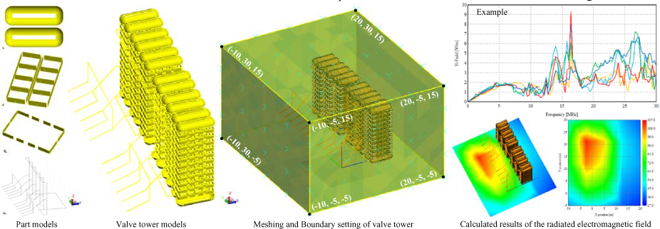
Figure 4: Calculation process for electromagnetic radiation harassment from converter towers.
To simplify the analysis, the conductors in this project were all modeled using conductors with a radius of 0.01 m (it was verified by comparison that changes in the radius of the conductors when calculating the radiation field had little effect on the calculation results). The metal frame is modeled using metal-faced conductors, without regard to the thickness of the metal frame, which is assumed to be a thin conductor plate made up of perfectly pure conductors. The final calculation process for the commutator tower is shown in Figure 4.
In the part models in Figure 4, the equalizer cover is insulated from the valve tower. The interior of the converter module can be simplified to 10 thyristors in series. The equalizer frame is connected to the valve tower at both the front and the rear, with the middle section insulated from the tower. The electrical connection contains all the wiring of the converter tower inside the converter valve hall. In this case, the current source is at the terminals of the converter transformer. When setting the boundaries, the coordinates of the rectangular boundary vertices are given, which is the basis information for the later analysis of the radiation properties.
III. ANALYSIS OF ELECTROMAGNETIC RADIATION
A Variation characteristics with frequency
As shown in Figure 5, it is the calculation result of the radiated electromagnetic field of the converter valve tower at (10,12.5,5) in the 150 kHz to 30 MHz frequency band. Among them, Figure 5 (a) is the amplitude-frequency characteristic of the radiated electric field, and Figure 5 (b) is the amplitude-frequency characteristic of the radiated magnetic field.
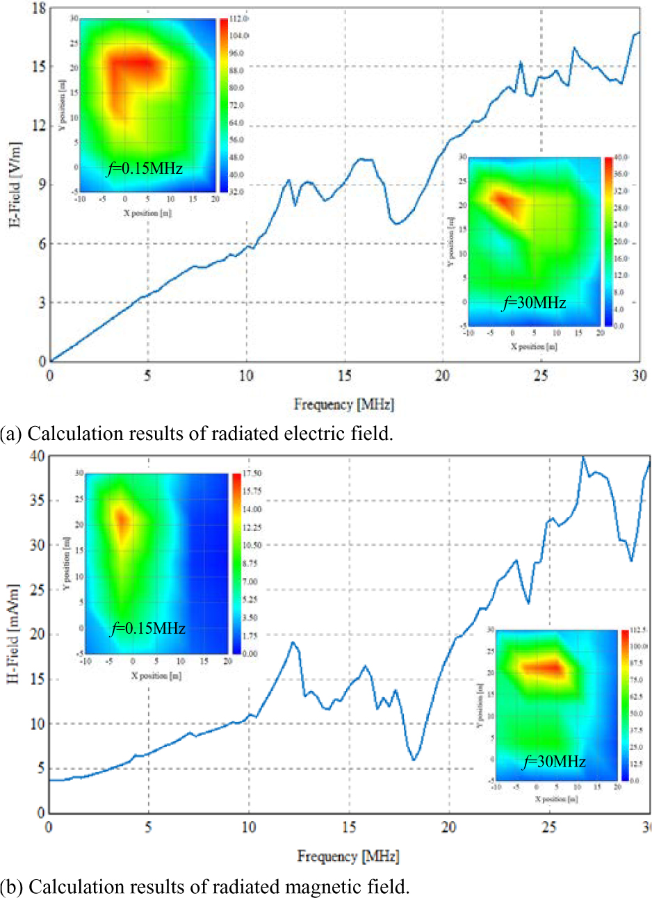
Figure 5: Calculation results of the converter valve tower at (-10, 12.5, 5).
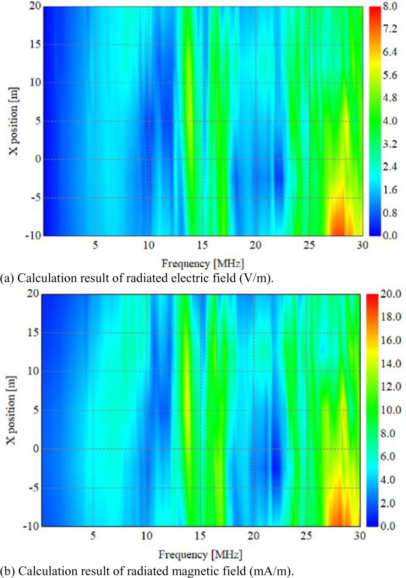
Figure 6: The attenuation characteristics in the X-axis direction.
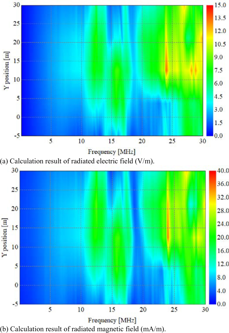
Figure 7: The attenuation characteristics in the Y-axis direction.
It can be seen that the value of the radiated electric field is much larger than the value of the radiated magnetic field, which is about 1000 times. Therefore, when assessing the electromagnetic compatibility of converter valve towers, the radiated electric field should be the first choice to be assessed. In addition, through the electromagnetic field cloud diagrams at f = 0.15 MHz and f = 30 MHz, it can be seen that on the plane of Z = 5 m, the positions of the maximum radiation of the electric field and the magnetic field appear close. Therefore, if the communication facilities are placed in the air of the converter valve hall, the right side should be considered as much as possible, and the radiated electric field and radiated magnetic field in this direction are relatively small.
B Attenuation characteristics
As shown in Figure 6, it is the calculation result of the radiated electromagnetic field of the converter valve tower at point (X, 5, 15). It can be seen that in the X-axis direction, the calculated values of electromagnetic fields at different frequency points all show an attenuation trend on the X-axis. On this straight line, the attenuation characteristics of the electromagnetic field are almost identical.

Figure 8: The attenuation characteristics in the Z-axis direction.
As shown in Figure 7, it is the calculation result of the radiated electromagnetic field of the converter valve tower at point (10, Y, 15). It can be seen that on the Y-axis, the calculated electromagnetic field values all show a trend of first increasing and then decreasing, and the radiated electromagnetic field is the largest in the middle of the Y-axis.
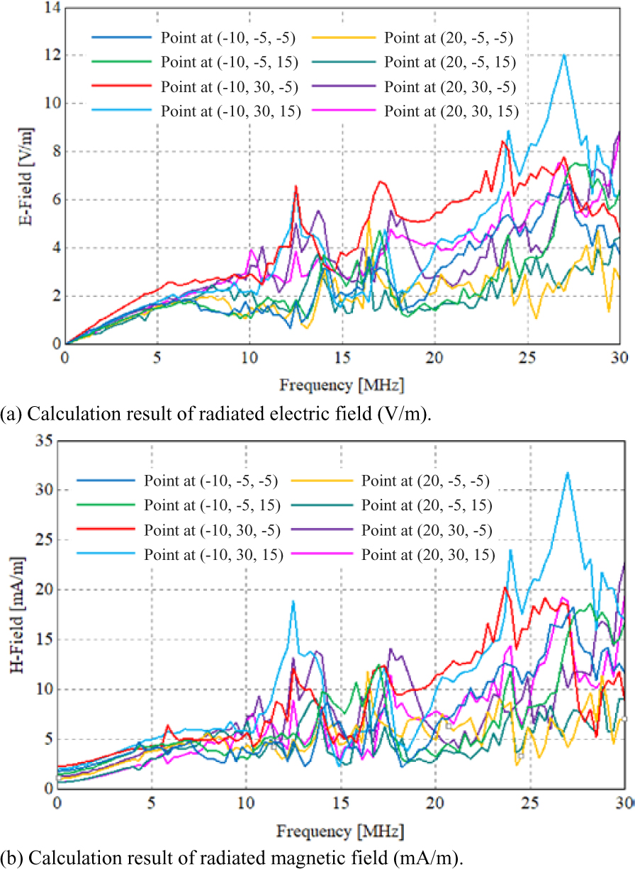
Figure 9: Azimuthal characteristics of the radiated electromagnetic field.
As shown in Figure 8, it is the calculation result of the radiated electromagnetic field of the converter valve tower at point (10, 12.5, Z). It can be seen that the attenuation characteristic of the electric field value in the Z-axis direction is not obvious and can be approximately regarded as unchanged; the attenuation characteristic of the magnetic field value in the Z-axis direction is related to the frequency point. Among them, the higher the frequency is, the greater the electromagnetic field value.
C Azimuthal characteristics
To further demonstrate the azimuthal characteristics of the radiated electromagnetic field of the converter tower, the electromagnetic field values at eight near-field boundary points were calculated, as shown in Figure 9. It can be seen that within the 25-30 MHz band, the electromagnetic field values are greatest at points (10, 30, 15) and smallest at points (20, 5, 5). Therefore, when placing communication equipment inside the converter hall, it should be placed at point (20, 5, 5) as far as possible, so that it receives less electromagnetic disturbance.
IV. CONCLUSION
In this paper, the calculation method of electromagnetic radiation of high-voltage converter valve tower is proposed, and the attenuation characteristics of radiation field in space are analyzed, and the strongest and weakest positions of radiation electromagnetic field in the converter valve hall are clarified. It is suggested that when placing communication equipment in the converter valve hall, it should be placed in the lower right corner of the converter valve hall as far as possible. The proposed method can determine the spatial distribution of the radiation field inside the converter valve hall, and, based on this, the immunity requirements for communication equipment are proposed. In the future, combined with the experimental measurement method, the electromagnetic compatibility measures between the communication equipment and the converter valve are formulated.
ACKNOWLEDGEMENT
This work was supported by the Technical Project of State Grid Ningxia Electric Power Co., Ltd. 5229CG21000D.
REFERENCES
[1] M. Wang, T. An, H. Ergun, Y. Lan, B. Andersen, M. Szechtman, and W. Leterm, et al., “Review and outlook of HVDC grids as backbone of transmission system,” CSEE Journal of Power and Energy Systems, vol. 7, no. 4, pp. 797-810, Jul. 2021.
[2] B. Gao, F. Yang, M. Chen, P. Duan, Q.-J. Peng, and Y. Yang, “An improved mlpg method and application in the calculation Of electro-thermal field Of transmission line,” Applied Computational Electromagnetics Society (ACES) Journal, vol. 30, no. 02, pp. 157-166, Aug. 2021.
[3] H. Lee, M. Asif, K. Park, and B. Lee, “Feasible application study of several types of superconducting fault current limiters in HVDC grids,” IEEE Transactions on Applied Superconductivity, vol. 28, no. 4, pp. 1-5, Jun. 2018.
[4] E. Jin, Z. Song, X. Yang, and X. Yu, “Improved thevenin equivalent model of MMC considering pre-charge conditions and DC side fault conditions,” Applied Computational Electromagnetics Society (ACES) Journal, vol. 36, no. 6, pp. 796-805, Nov. 2021.
[5] S. M. M. Mirtalaei, S. H. H. Sadeghi, and R. Moini, “A method-of-moments model for determination of radiated magnetic field from switch-mode power supplies components using near-field measurement data,” Applied Computational Electromagnetics Society (ACES) Journal, vol. 28, no. 08, pp. 672-679, Oct. 2021.
[6] R. T. Harrold, “The spectrum analyzer to the measurement of EHV power line noise,” IEEE Transactions on Power Apparatus and Systems, vol. 90, no. 2, pp. 1837-1847, 1971.
[7] S. A. Annestrand, “Radio interference from HVDC converter stations,” IEEE Transactions on Power Apparatus and Systems, PAS-90(3), pp. 874-882, 1972.
[8] P. S. Maruvada and T. Gilsig, “A method of calculating the RI from HVDC converter stations,” IEEE Transactions on Power Apparatus and Systems, vol. 92, no. 3, pp. 1009-1018, 1973.
[9] A. R. Morse, “Field measurements on the Nelson River HVDC line including comparisons with test line data and calculated profiles,” Proceedings of the Canadian PowerConference, Montreal, Canada, pp. 437-440, 1976.
[10] A. R. Morse, “Field measurements of station-generated RI on the Nelson River HVDC line,” Proceedings of the International Electrical and Electronics Conference, Toronto, Canada, pp. 78-79, 1976.
[11] D. J. Melvolil, L. Haglof, and P. Degn, “Carrier frequency harmonics generated by HVDC conversion,” IEEE Transactions on Power Apparatus and Systems, vol. 99, no. 2, pp. 564-575, 1980.
[12] G. H. Bacon, D. L. Hedrick, and J. J. Fiedler, “Power line carrier application considerations involving HVDC transmission,” IEEE Transactions on Power Apparatus and System, vol. 99, no. 3, pp. 1089-1096, 1980.
[13] B. W. Jakel and Q.-B. Tu, “Electromagnetic environment near HVDC thyristor valves // 11th international symposium on high voltage engineering,” vol. 2, no. 2, pp. 47-50, 1999.
[14] Y. Liu, S. A. Sebo, and R. Caldecott, “Modeling of converter transformer using frequency domain terminal impedance measurements,” IEEE Transactions on Power Delivery, vol. 8, no. 1, pp. 66-72, 1993.
[15] D. G. Kasten, R. Caldecott, S. A. Sebo, and Y. Liu, “A computer program for HVDC Converter station RF noise calculations,” IEEE Transactions on Power Delivery, vol. 9, no. 2, pp. 750-755, Apr. 1994.
[16] P. S. Maruvada, R. A. Malewski, and P. S. Wong, “Measurement of the electromagnetic environment of HVDC converter stations,” IEEE Power Engineering Review, vol. 9, no. 4, pp. 73-74, 2007.
[17] R. Caldecott, R. V. Devore, and D. G. Kasten, “HVDC converter station tests in the 0.1 to 5MHz frequency,” IEEE Transactions on Power Delivery, vol. 3, no. 3, pp. 971-977, 1988.
[18] Y. Murata, S. Tanabe, and M. Tadokoroetc, “3D-MoM analysis of radio frequency noise radiation from HVDC converter station,” IEEE International Symposium, pp. 980-985, 1999.
BIOGRAPHIES

Hong Sen Zou is currently working with the State Grid Ningxia Electric Power Co., Ltd. Maintenance Company. His research interest includes power electronics and power system automation.

Lin Zheng is currently working with the State Key Laboratory of Advanced Power Transmission Technology (Global Energy Interconnection Research Institute Co., Ltd.). His research interest includes the development and engineering of control and protection system for HVDC and DC grid applications.

Yuan Zhang is currently working with the State Grid Ningxia Electric Power Co., Ltd. Maintenance Company. His research interest includes power electronics and power system automation.

Jianan Zhang is currently working with the State Key Laboratory of Advanced Power Transmission Technology (Global Energy Interconnection Research Institute Co., Ltd.). Her research interest includes the development and engineering of control and protection system for HVDC and DC grid applications.

Yajie Wang is currently working with the State Key Laboratory of Advanced Power Transmission Technology (Global Energy Interconnection Research Institute Co., Ltd.). Her research interest includes the development and engineering of control and protection system for HVDC and DC grid applications.

Huafeng Wang is currently working with the State Key Laboratory of Advanced Power Transmission Technology (Global Energy Interconnection Research Institute Co., Ltd.). His research interest includes the HVDC control and protection and valve control system of converter valves.
ACES JOURNAL, Vol. 37, No. 5, 624–631.
doi: 10.13052/2022.ACES.J.370512
© 2021 River Publishers