Wideband Printed Antipodal Vivaldi Antenna using Straight Slots for UHF DVB-T/T2 Applications
Na-Rae Kwon, Seong-Hyeop Ahn, and Wang-Sang Lee
Department of Electronic Engineering, Gyeongsang National University (GNU), 501, Jinju-daero, Jinju, Gyeongnam, 52828, Republic of Korea
wsang@gnu.ac.kr
*Corresponding author
Submitted On: December 28, 2021; Accepted On: August 15, 2022
Abstract
This paper presents a wideband printed antipodal Vivaldi antenna using straight slots for UHF DVB-T/T2 applications covering a frequency range of 470–862 MHz. The proposed antenna consists of two radiation flares with straight slots and a feeding line. A wideband impedance matching was achieved by inserting the slots between the flares and the feeding line. For the experimental verification of the proposed antenna, it was fabricated on a flat circular printed circuit board (PCB) substrate with a radius of 0.25 , where is the wavelength at 0.74 GHz (the center frequency of the operating band). The measured 10 dB impedance bandwidth and maximum gain were approximately 72.1% (0.47–1.00 GHz) and 2.57 dBi, respectively. Due to the addition of the slots, the impedance bandwidth of the proposed antenna was improved by approximately 212% compared with the Vivaldi antenna without slots.
Index Terms: antipodal Vivaldi antenna, DVB-T/T2, straight slots, UHF applications, wideband.
I. INTRODUCTION
With the recent advances in internet-of-things technology, stable wireless communication between various devices has become crucial, with high-performance antennas required. A Vivaldi antenna meets the needs of many wireless devices since it exhibits a wide bandwidth, high gain, stable radiation patterns, and low radiation losses. In addition, it is a so-called tapered slot antenna fed into a tapered balanced slot line with a high input impedance (approximately 300 ). To match the high input impedance of the slot line with the 50 feed line, a balun capable of converting the input impedance of the antenna is required. To this end, coplanar and antipodal feeding methods are mainly adopted for Vivaldi antennas [1]. Here, the coplanar Vivaldi antenna (CVA) adopts the balun feed using a microstrip line and a slot, ensuring that the CVA achieves a high gain and symmetrical radiation patterns [2]. However, due to the exponential tapered radiation unit, the cross-polarization of the CVA is large, the return loss is reduced, and the beam width is narrow. In addition, the CVA has weak competitiveness about miniaturization because the slot line including the balun, is built on one side of the PCB. To overcome these disadvantages, Gazit [3] devised an antipodal Vivaldi antenna (AVA) where the radiation plates, including the tapered balun feed, are fabricated on both sides of PCB, meaning that the AVA is smaller than the CVA. Furthermore, an AVA can be used in systems sensitive to polarization due to the small cross-polarization, while an AVA has better characteristics than a tapered balun CVA since the tapered ground is laid along the microstrip feed line in the former, meaning that the antenna can perform impedance matching with a broader bandwidth [4].
Parasitic patches [5–7] or metamaterials [8–11] are often placed between the flares to improve the directivity of the AVA [12]. Using these characteristics, an AVA can be used for various applications, including ultra- wideband (UWB), radar, Ka-band, and 5G device applications [13], while the antenna has also recently been developed for applications such as vehicle to everything (V2X) communication and energy harvesting [14–15]. Meanwhile, the adoption of AVAs for medical applications has been described in various recent studies [16–17], with the addition of notches inside and outside of the antenna radiation arms in [17] resulting in miniaturization and constant gain. A previous study [18] studied frequency reconfigurable antennas that construct switching circuits with pin diodes at ring-shaped slots between the Vivaldi antenna arms. Recently, AVA using meander line-shaped slots and frequency selective surface (FSS) to enhance the gain and the impedance bandwidth was researched for IoT/WLANapplications [19].
Meanwhile, researchers have turned their attention to investing in a balanced AVA (BAVA), which is essentially an AVA developed to suit the UWB environment. However, while the BAVA has a wider impedance bandwidth than the AVA, it involves the disadvantages of having a complex design and being expensive. While many advances concerning Vivaldi antennas have been made through AVA research, bulky structures remain inevitable due to the nature of the Vivaldi antenna itself. As such, various studies have been conducted about the miniaturization of AVAs. Here lowering the operating frequency by increasing the electrical length of the antenna is a typical method for miniaturizing the antenna, while the most commonly used approach involves adopting a corrugate structure for the AVA [24–25], which can effectively increase the electrical length of the antenna [20–23], with the tapered structure allowing for reducing the overall size while maintaining or improving the basic characteristics (e.g., radiation patterns and gains) of the antenna. In a previous study, miniaturization using imaginary effects has also recently been researched [26], while the antenna’s characteristics can be improved through using slots in a planar AVA. Here, antenna miniaturization can be implemented to improve the electrical length by applying various-shaped slots to the feeding and radiating parts of the AVA or the space between them [27–29].
Meanwhile, various studies on antennas for ultra-high frequency (UHF) digital television (DTV) bands have been conducted. In [30], DTV transmitting antennas that achieved a low voltage standing wave ratio (SWR) in the DTV broadcasting system using stepped complex impedance transformers and a broadband matching network were devised, whereas in [31], an antenna for Korea’s UHD TV frequency range (470–771 MHz) was investigated. This antenna implements various dipoles and patches on the transparent sheets with optical transparency of 70%. However, while the antenna is compact and inconspicuous, it has a bulky ground size.
With all this in mind, in this paper, we propose a miniaturized wideband AVA with a straight slot that meets the digital video broadcasting-terrestrial/version-2 (DVB-T/T2) band range (470–862 MHz) [32], a TV frequency band mainly used in Europe and Asia.
II. PROPOSED ANTIPODAL VIVALDI ANTENNA CONFIGURATION
In general, the width (W) of the Vivaldi antenna for effective radiation can be described as follows:
| (1) |
where c is the velocity of light in free space, f is a lower frequency, and is a relative permittivity of the substrate [33]. According to (1), when the width of the antenna decreases, the f increases, and the bandwidth decreases. However, by adding straight slots to the feeding portion of the Vivaldi antenna, miniaturization and bandwidth improvement can be achieved. This is the most effective and simple-to-manufacture slot technology for maintaining the f even if the width of the antenna is reduced. In addition, the proposed antenna was designed with a round-shaped plate of the radiation portion to reduce the side lobe.
The structure of the proposed AVA is shown in Fig. 1 (a). The substrate presents a circular shape and has a radius of R = 100 mm. The optimal parameters of the proposed antenna are shown in Table 1. The proposed antenna is fed by a tapered balun to ensure stable signal input. Meanwhile, Figs. 2 (a) and 2 (b) show the equivalent circuit of the proposed antenna with and without straight slots. As shown in Fig. 2 (a), the AVA can be modeled according to the transmission line with antenna impedance (Z) whereas as shown in Fig. 2 (b), the straight slots can be equivalent to a series of short stubs for broad impedance matching.
Table 1: Geometric design parameters of the proposed antenna (unit: mm)
| 168.1 | 136.5 | 100 | 195 | 85.2 |
| 2.2 | 45 | 20 | 5 | 67 |
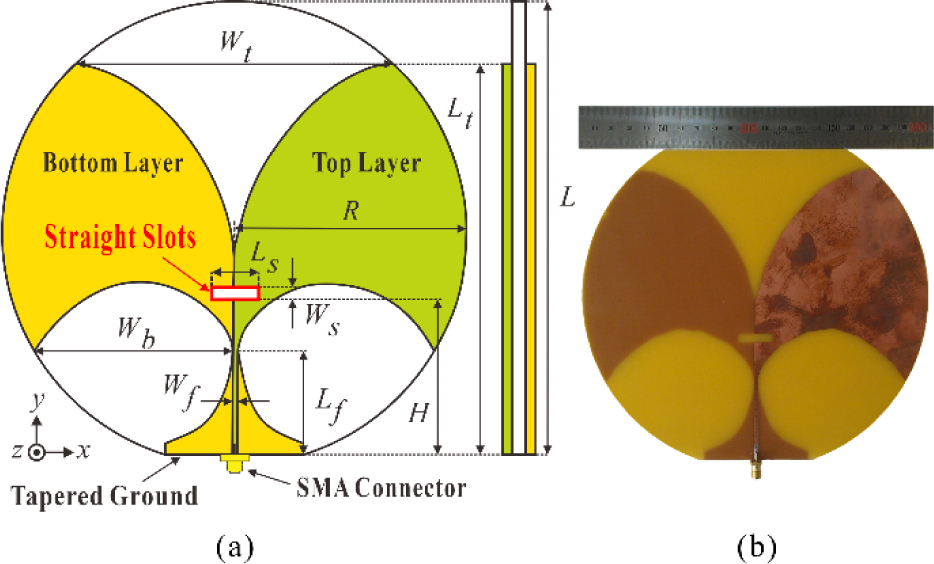
Figure 1: Proposed antipodal Vivaldi antenna with straight slots: (a) all geometry dimensions with design parameters and (b) a fabricated antenna prototype.
Meanwhile, using a commercial full-wave electromagnetic tool (CST Microwave Studio 2021), the optimal parameter value was found by observing the change in input impedance according to the length, width, and position of the slot. Figure 3 shows the simulated input impedance variations of the proposed antenna on a Smith chart with respect to different widths (W), lengths (L) and positions (H). The impedance chart in Fig. 3 (a) shows when there are no slots (P), the input impedance has capacitive reactance, whereas after adding the slots (P), the inductive reactance increases, resulting in the total input impedance being a real value. Numerically, the input impedance of the antenna without the slots was 64.62–j39.79 (P) at 0.67 GHz, whereas after the addition of the slots, this became 61.75–j0.09 (P). As a result, the impedance trajectory was contained within the SWR 2:1 circle, which improved the impedance bandwidth. As Figs. 3 (b) and 3 (c) show, the input reactance increased significantly compared with the input resistance as the L and W increased, whereas as Fig. 3 (d) shows, the resistance increased when the slot position was closer to the feeding line.
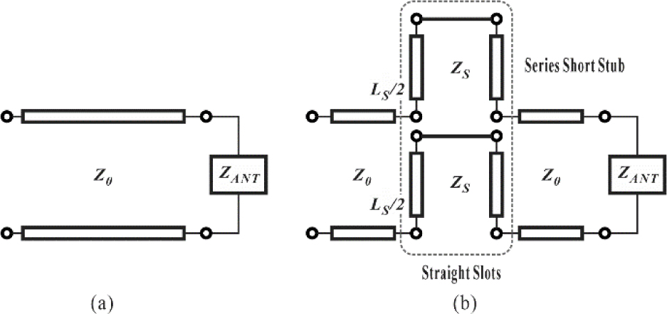
Figure 2: Equivalent circuit of the proposed antenna (a) without and (b) with straight slots.
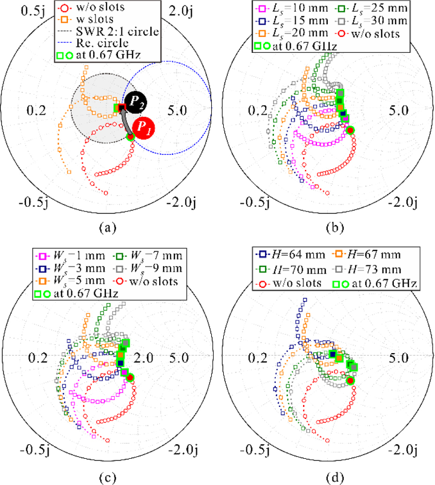
Figure 3: Simulated input impedance variations on Smith chart: (a) with and without the slots, (b) with respect to various lengths of the slots, (c) with respect to various widths of the slots, and (d) with respect to various positions of the slots.
Meanwhile, as shown in Figs. 4 (a) and 4 (b), input impedance variations depending on the size of the slots were clearly observed. As Fig. 4 (a) shows, the resistance remained almost constant as the L increased,but the reactance increased significantly. Similarly, as shown in Fig. 4 (b), an increase in W resulted in a relatively constant resistance but an increase in reactance. The large slot size increased the inductive reactance of the short serial stub, which verified the equivalent circuit shown in Fig. 2 (b). Meanwhile, the parameter studies allowed us to achieve the impedance bandwidth optimization of the antenna by adjusting the length, width, and position of the slots such that the proposed antenna achieved a wide impedance bandwidth. Here, the frequency band with a reactance close to zero was the widest when the slot size (L = 20 mm and W = 5 mm). As a result, The proposed antenna was optimized when the slot size and positions were as follows: L = 20 mm, W = 5 mm, and H = 67 mm.
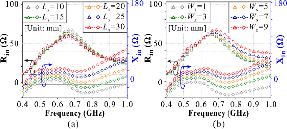
Figure 4: Real and imaginary parts of the simulated input impedance via the straight slots on the proposed antenna: (a) according to different lengths (L) and (b) different widths (W).
Figure 5 shows the simulated surface current and E-field distributions of the proposed antenna for the different phases (0, 90, 180, and 270) at 670 MHz.
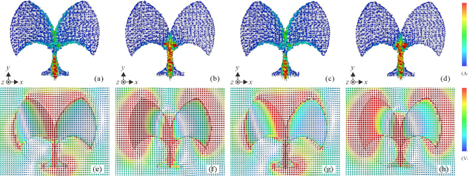
Figure 5: Simulated surface current and E-field distributions ((a)–(d) and (e)–(f)) of the proposed antenna with respect to the different phases at 670 MHz: (a) and (e) 0, (b) and (f) 90, (c) and (g) 180, and (d) and (h) 270.
III. RESULTS AND DISCUSSIONS
An image of the prototype of the proposed antenna is shown in Fig. 1 (b), with the proposed antenna fabricated on a 1.2 mm thick FR-4 substrate with a relative permittivity () of 4.3 and a loss tangent (tan ) of 0.025. The reference antenna and the proposed antenna were measured in the environment depicted in Fig. 6. The measuring setup for radiation performances utilizing a horn antenna in the anechoic chamber room is shown in Fig. 6 (a). A vector network analyzer was used to measure the reflection coefficient, as shown in Fig. 6 (b). Figure 7 present the simulated and measured results for the reference antenna without slots and the proposed antenna with straight slots. Here, Fig. 7 (a) shows the reflection coefficients to the frequency. The addition of the proposed slots made it possible to match the impedance of the antenna. The measured 10 dB impedance bandwidth of the proposed antenna was 530 MHz, approximately three times higher than the reference antenna (175 MHz). As a result, the proposed antenna achieved an impedance bandwidth of approximately 72.1%. As shown in Fig. 7 (b), the proposed slots improved the gain at the operating frequency. The maximum measured gain of the reference and the proposed antenna was approximately 2.14 and 2.57 dBi, respectively. Furthermore, as shown in Fig. 7 (b), the proposed antenna with added slots has significantly higher measured total efficiency above 0.7 GHz than the reference antenna.
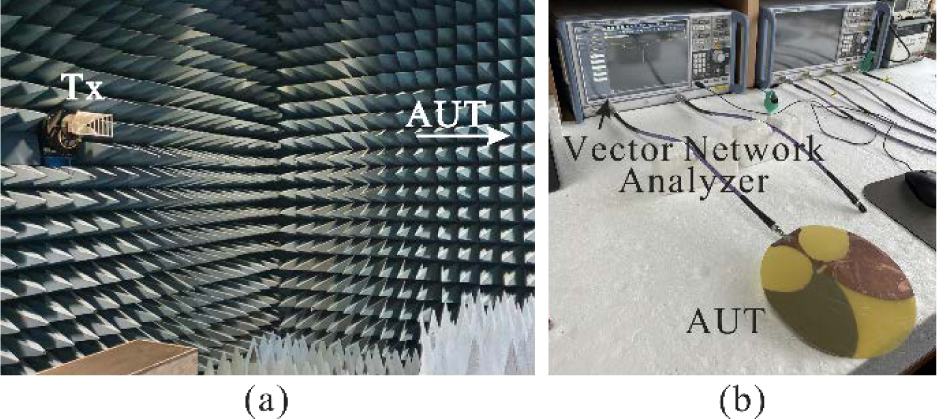
Figure 6: Measurement setup of the proposed antenna: (a) radiation pattern measurement and (b) reflection coefficient measurement.
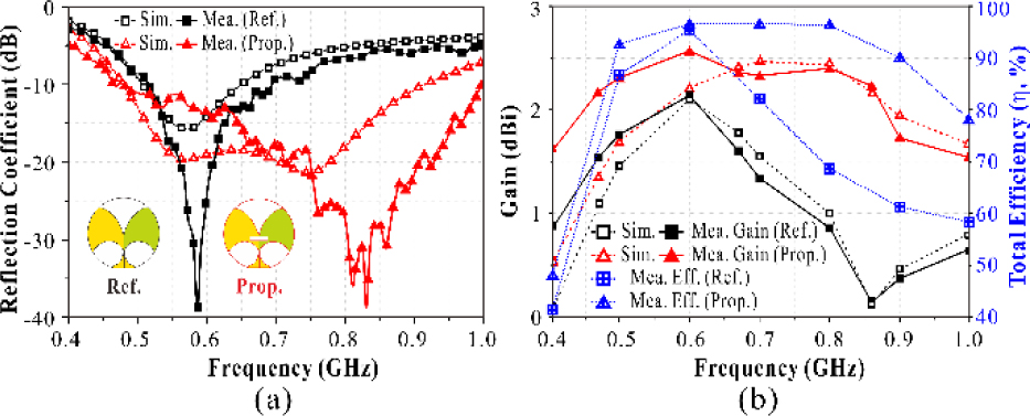
Figure 7: Simulated and measured results of the proposed antenna in relation to the frequencies: (a) reflection coefficients, (b) peak gains and total efficiency.
Figure 8 shows the simulated and measured radiation patterns of the proposed antenna at the x-y and x-z planes in the operating frequencies of 470, 670, and 860 MHz. Here, the proposed antenna presented an omnidirectional radiation pattern in the azimuth plane, whereas in the elevation plane, as the frequency increased, the antenna presented a directional beam in the y-axis direction.
Table 2: Comparison between previous works and the proposed antenna
| Ref. | fc (GHz) |
BW (%) | Gain (dBi) | Size () |
| [5] | 17 | 176.5 | 12 | 6.26 2.95 0.07 |
| [8] | 1.4 | 100 | 10.5 | 1.11 1.05 0.06 |
| [14] | 4.14 | 172.9 | 9.2 | 2.07 2.04 2.04 |
| [15] | 6.41 | 174.7 | 6.3 | 2.16 3.20 0.03 |
| [26] | 1.7 | 117.7 | 8.3 | 1.16 1.14 0.002 |
| [29] | 0.66 | 62.4 | 11.6 | 2.66 1.00 0.34 |
| [30] | 0.62 | 54.5 | 2.4 | 0.60 0.22 0.13 |
| [34] | 2.4 | 75 | 6.66 | 0.95 0.95 0.01 |
| Prop. | 0.74 | 77.9 | 2.57 | 0.48 0.49 0.002 |
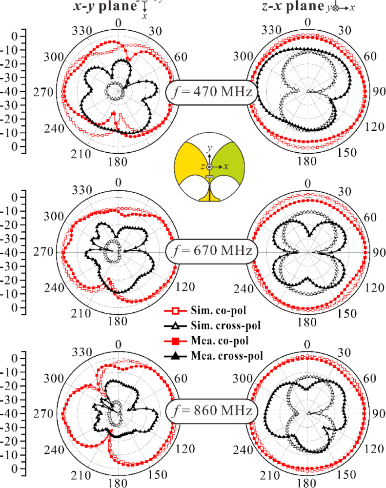
Figure 8: Simulated and measured radiation patterns of the proposed antenna at the x-y and x-z planes in the operating frequencies of 470, 670, and 860 MHz.
Table 2 presents a comparison of the proposed antenna with those reported in previous works. Compared with the Vivaldi antennas described in previous studies, the proposed antenna demonstrated an improved impedance bandwidth due to the addition of the straight slots to the antenna radiator. It was comparatively small in size (0.48 0.49 0.002 ) based on the center frequency wavelength (f).
IV. CONCLUSION
In this paper, a method for miniaturizing a wideband Vivaldi antenna using straight slots was presented. The method can be easily implemented by adding slots to the antenna radiator. Using this method, we devised a wideband printed AVA for UHF DVB-T/T2 applications. Both the proposed antenna and the miniaturization methods will prove useful in designing various directional antennas.
ACKNOWLEDGMENT
This work was supported in part by the Korean Government (MSIT) through the National Research Foundation of Korea under Grant 2019R1C1C1008102 and in part by the MSIT(Ministry of Science and ICT), Korea, under the ICAN(ICT Challenge and Advanced Network of HRD) program (IITP-2022-RS-2022-00156409) supervised by the IITP (Institute of Information & Communications Technology Planning & Evaluation).
REFERENCES
[1] Bhattacharjee, A. Bhawal, A. Karmakar, A. Saha, and D. Bhattacharya, “Vivaldi antennas: a historical review and current state of art,” Int. J. Microw. Wirel. Tech., vol. 13, no. 8, pp. 833-850, 2021.
[2] J. Puskely, J. Lacik, Z. Raida, and H. Arthaber, “High gain dielectric loaded Vivaldi antenna for Ka-band application,” IEEE Antennas Wirel. Propag. Lett., vol. 15, pp. 2004-2007, 2016.
[3] Gazit and Ehud, “Improved design of the vivaldi antenna,” IEE Proceedings H-Microw., Antennas Propag., vol. 135, no. 2, pp. 89-92, 1988.
[4] C. J. Hodgkinson, D. E. Anagnostou, and S. K. Podilchak, “Compact UWB antipodal vivaldi array for beam steering applications,” 2021 15th European Conf. Antennas Propag., pp. 1-5, 2021.
[5] I. T. Nassar and T. M. Weller, “A novel method for improving antipodal Vivaldi antenna performance,” IEEE Trans. Antennas Propag., voil. 63, no. 7, pp. 3321-3324, 2015.
[6] Z. Li, X. Kang, J. Su, Q. Guo, Y. Yang, and J. Wang, “A wideband endfire conformal Vivaldi antenna array mounted on a dielectric cone,” Int. J. Antennas Propag., vol. 2016, 2016.
[7] X. Zhang, Y. Chen, M. Tian, J. Liu, and H. Liu, “A compact wideband antipodal Vivaldi antenna design,” Int. J. RF Microw. Comput.-Aided Eng., vol. 29, no. 4, pp. e21598, 2018.
[8] H. Cheng, H. Yang, Y. Li, and Y. Chen, “A compact vivaldi antenna with artificial material lens and sidelobe suppressor for GPR applications,” IEEE Access, vol. 8, pp. 64056-64063, 2020.
[9] S. Zhu, H. Liu, and P. Wen, “A new method for achieving miniaturization and gain enhancement of vivaldi antenna array based on anisotropic metasurface,” IEEE Trans. Antennas Propag., vol. 67, no. 3, pp. 1952-1956, 2019.
[10] M. Sun, Z. N. Chen, and X. Qing, “Gain enhancement of 60-GHz antipodal tapered slot antenna using zero-index metamaterial,” IEEE Trans. Antennas Propag., vol. 61, no. 4, pp. 1741-1746, 2013.
[11] X. Li, H. Zhou, Z. Gao, H. Wang, and G. Lv, “Metamaterial slabs covered UWB antipodal vivaldi antenna,” IEEE Antennas Wirel. Propag. Lett., vol. 16, pp. 2943-2946, 2017.
[12] A. S. Dixit and S. Kumar, “A survey of performance enhancement techniques of antipodal vivaldi antenna,” IEEE Access, vol. 8, pp. 45774-45796, 2020.
[13] S. Kumar, A. S. Dixit, R. R. Malekar, H. D. Raut, and L. K. Shevada, “Fifth generation antennas: A comprehensive review of design and performance enhancement techniques,” IEEE Access, vol. 8, pp. 163568-163593, 2020.
[14] P. A. Dzagbletey, J. Shim, and J. Chung, “Quarter-wave balun fed vivaldi antenna pair for V2X communication measurement,” IEEE Trans. Antennas Propag., vol. 67, no. 3, pp. 1957-1962, 2019.
[15] J. Schneider, M. Mrnka, J. Gamec, M. Gamcova, and Z. Raida, “Vivaldi antenna for RF energy harvesting,” Radioengineering, vol. 25, no. 4, pp. 666-671, 2016.
[16] A. M. De Oliveira, A. M. de Oliveira Neto, and M. B. Perotoni, “A fern antipodal vivaldi antenna for near-field microwave imaging medical applications,” IEEE Trans. Antennas Propag., vol. 69, no. 12, pp. 8816-8829, Dec. 2021.
[17] A. Alkhaibari, A. F. Sheta, and I. Elshafiey, “Notched antipodal vivaldi antenna for biomedical applications,” 2017 7th Int. Conf. Model. Simul. Appl. Optim., pp. 1-4, 2017.
[18] R. Herzi, A. Gharsallah, M. A. Boujemaa, and F. Choubani, “Frequency reconfigurable Vivaldi antenna with switched resonators for wireless applications,” Int. J. Adv. Comput. Sci. Appl., vol. 10, no. 5, pp. 414-421, 2019.
[19] F. Güneş, İ. Ö. Evranos, M. A. Belen, P. Mahouti, and M. Palandöken, “A compact triband antipodal Vivaldi antenna with frequency selective surface inspired director for IoT/WLAN applications,” Wireless Netw., vol. 27, pp. 3195-3205, 2021.
[20] A. M. Abbosh, “Miniaturized microstrip-fed tapered-slot antenna with ultrawideband performance,” IEEE Antennas Wirel. Propag. Lett., vol. 8, pp. 690-692, 2009.
[21] A. S. Dixit and S. Kumar, “A miniaturized antipodal vivaldi antenna for 5G communication applications,” 2020 7th Int. Conf. Signal Process. Integr. Netw., pp. 800-803, 2020.
[22] Moosazadeh and Mahdi, “Sidelobe level reduction using teflon for a microwave and millimetre-wave antipodal vivaldi antenna,” IET Microw. Antennas Propag., vol. 14, no. 6, pp. 474-478, 2020.
[23] M. Abbak, M. N. Akıncı, M. Ç ayören, and I. Akduman, “Experimental microwave imaging with a novel corrugated vivaldi antenna,” IEEE Trans. Antennas Propag., vol. 65, no. 6, pp. 3320-3307, 2017.
[24] R. Natarajan, J. V. George, M. Kanagasabai, and A. Kumar Shrivastav, “A compact antipodal vivaldi antenna for UWB applications,” IEEE Antennas Wirel. Propag. Lett., vol. 14, pp. 1557-1560,2015.
[25] Dastranj and Aliakbar, “Wideband antipodal vivaldi antenna with enhanced radiation parameters,” IET Microw. Antennas Propag., vol. 9, no. 15, pp. 1755-1760, 2015.
[26] Z. Yin, G. He, X. Yang, and S. Gao, “Miniaturized ultrawideband half- mode vivaldi antenna based on mirror image theory,” IEEE Antennas Wirel. Propag. Lett., vol. 19, no. 4, pp. 695-699,2020.
[27] Y. Dong, J. Choi, and T. Itoh, “Vivaldi antenna with pattern diversity for 0.7 to 2.7 GHz cellular band applications,” IEEE Antennas Wirel. Propag. Lett., vol. 17, no. 2, pp. 247-250, 2018.
[28] Y. Liu, W. Zhou, S. Yang, W. Li, P. Li, and S. Yang, “A novel miniaturized vivaldi antenna using tapered slot edge with resonant cavity structure for ultrawideband applications,” IEEE Antennas Wirel. Propag. Lett., vol. 15, pp. 1881-1884, 2016.
[29] P. Ludlow and V. F. Fusco, “Antipodal vivaldi antenna with tuneable band rejection capability,” IET Microw. Antennas Propag., vol. 5, no. 3, pp. 372-378, 2011.
[30] H. Yu, S. Fang, L. Jiang, and H. Liu, “A full-band digital television transmitting antenna array with dual-layer bowtie dipole unit,” IEEE Access, vol. 8, pp. 102138-102145, 2020.
[31] P. Duy Tung and C. W. Jung, “Optically transparent wideband dipole and patch external antennas using metal mesh for UHD TV applications,” IEEE Trans. Antennas Propag., vol. 68, no. 3, pp. 1907-1917, 2020.
[32] C. Huang, B. Jeng, and J. Kuo, “Grating monopole antenna for DVB- T applications,” IEEE Trans. Antennas Propag., vol. 56, no. 6, pp. 1775-1776, 2008.
[33] J. Y. Siddiqui, Y. M. M. Antar, A. P. Freundorfer, E. C. Smith, G. Morin, and T. Thayaparan, “Design of an ultrawideband antipodal tapered slot antenna using elliptical strip conductors,” IEEE Antennas Wirel. Propag. Lett., vol. 10, pp. 251-254,2011.
[34] D. Oliveira, M. Alexandre, A. M. de Oliveira Neto, and M. B. Perotoni, “A fern antipodal vivaldi antenna for near-field microwave imaging medical applications,” IEEE Trans. Antennas Propag., vol. 69, no. 12, pp. 8816-8829, 2021.
BIOGRAPHIES

Na-Rae Kwon received the B.S. degree in electronic engineering from Gyeongsang National University (GNU), Jinju, South Korea, in 2017, where she is currently pursuing the M.S. degree.
Her current research interests include wireless power transfer and communication systems, RF/Microwave circuit and system, and RFID/IoT sensors.

Seong-Hyeop Ahn received the B.S. and M.S. degrees in electronic engineering from Gyeongsang National University, Jinju, South Korea, in 2018 and 2020, respectively, and is currently working toward the Ph.D. degree.
His research interests are near- and far-field wireless power transfer and data communication system, high-power microwave system with slotted waveguides, and RF/microwave circuit and antenna designs.

Wang-Sang Lee received the B.S. degree from Soongsil University, Seoul, South Korea, in 2004, and the M.S. and Ph.D. degrees in electrical engineering from the Korea Advanced Institute of Science and Technology (KAIST), Daejeon, South Korea, in 2006 and 2013, respectively. From 2006 to 2010, he was with the Electromagnetic Compatibility Technology Center, Digital Industry Division, Korea Testing Laboratory (KTL), Ansan-si, South Korea, where he was involved in the international standardization for radio frequency identification (RFID) and photovoltaic systems as well as electromagnetic interference (EMI)/EMC analysis, modeling, and measurements for information technology devices. In 2013, he joined the Korea Railroad Research Institute (KRRI), Uiwang-si, South Korea, as a Senior Researcher, where he was involved in the position detection for high-speed railroad systems and microwave heating for low-vibration rapid tunnel excavation system. Since 2014, he has been an Associate Professor with the Department of Electronic Engineering, Gyeongsang National University (GNU), Jinju, South Korea. From 2018 to 2019, he was a Visiting Scholar with the ATHENA Group, Georgia Institute of Technology, Atlanta, GA, USA. His current research interests include near- and far-field wireless power and data communications systems, RF/microwave antenna, circuit, and system design, RFID/Internet of Things (IoT) sensors, and EMI/EMC.
Dr. Lee is a member of IEC/ISO JTC1/SC31, KIEES, IEIE, and KSR. He was a recipient of the Best Paper Award at IEEE RFID in 2013, the Kim Choong-Ki Award– Electrical Engineering Top Research Achievement Award at the Department of Electrical Engineering, KAIST, in 2013, the Best Ph.D. Dissertation Award at the Department of Electrical Engineering, KAIST, in 2014, the Young Researcher Award at KIEES in 2017, and the Best Paper Awards at IEIE in 2018 and KICS in 2019.
ACES JOURNAL, Vol. 37, No. 6, 726–732.
doi: 10.13052/2022.ACES.J.370608
© 2021 River Publishers