Eight-port Diagonal Antenna with High Isolation and High Efficiency for 5G Smartphone
Rui Shao, Junlin Wang*, Xin Wang*, and Yonghao Wang
1College of Electronic and Information Engineering, Inner Mongolia University, Hohhot, 010021, China
17853313635@163.com, *wangjunlin@imu.edu.cn, *wangxin219@imu.edu.cn, yhwangimu@163.com
Submitted On: January 24, 2022; Accepted On: September 12, 2022
Abstract
In this letter, an multiple-input-multiple-output (MIMO) antenna that operates in the sub-6 GHz (4.7-5.1 GHz) spectrum for 5G MIMO smartphone applications is presented. The design consists of a fully grounded plane with closely orthogonal antenna pairs placed symmetrically on the corners of the smartphone and each antenna element consists of an F-type monopole with dimensions of . Firstly, the diversity characteristics of orthogonally placed antennas are used to reduce the coupling between antennas. On the other hand, diagonal antennas are connected by a neutral line (NL) to further improve isolation and etched slots on the ground to reduce the coupling between antenna pairs. A good frequency bandwidth ( 10 dB) of 4.7-5.1 GHz has been obtained for the MIMO antenna, and the isolation is lower than 16 dB. In addition, total efficiency (TE) is greater than 77.5%, and the envelope correlation coefficient (ECC) is lower than 0.025. The fabricated antenna prototype is tested and offers good performance.
Index Terms: high efficiency, high isolation, MIMO, smartphone antenna.
1 INTRODUCTION
With the rapid development of communication technology, people’s demand for the throughput of mobile communication system is increasing, which has become the main factor for the fifth generation (5G) mobile communication. In the 5G era, it is compatible with 2G / 3G / 4G, WiFi, Bluetooth, satellite navigation and other systems and standards. The number of antennas in the system increases sharply, and the MIMO antenna is regarded as an appropriate choice for 5G mobile applications. One of the main challenges in MIMO antenna design is the isolation enhancement and low ECC within a compact size. Several techniques exist that can improve the isolation between antenna elements for mobile communication when they are closely spaced together.
Distance optimization and selection of different elements are easy methods without employing any other structure to suppress coupling between antennas [1, 4]. An ultra-wideband (3.3-6 GHz) eight-antenna MIMO array was better than 11 dB by selecting an appropriate distance between neighboring elements [4]. Since space is limited, the improvement of isolation is limited by adjusting only the distance between elements. However, adjusting the distance between elements to obtain acceptable isolation may result in a large size of the MIMO system, which cannot meet the requirements ofsmall space.
Adding external decoupling structure is an efficient method to further improve the isolation, such as the (NL) technique, defected ground structure (DGS) technique, and grounded branch. The NL technique is firstly presented by Diallo in 2006 [5]. The principle of this technology is that the NL connects the antenna radiation element, and the current generated in the NL is the same amplitude and opposite phase as the excited antenna, which cancels out the coupling current, thereby reducing the coupling between the antenna elements; this technique has been demonstrated successfully in [6, 8]. However, when the NL structure is connected to the antenna elements, the improper selection of the connection position will make it resonate with the radiator. The DGS is a slot structure etched on the ground. The slot structure can be equivalent to a filter, which limits the ground current from ant 1 to ant 2 to suppress the coupling caused by the current on the ground surface. High isolation can be realized by loading the DGS to block coupling current [9, 11]. In general, when using the DGS to improve the isolation of the MIMO antenna, the etched structure needs to satisfy that its length is greater than a quarter wavelength. The disadvantage of the DGS is that when the antenna works at a high frequency, the overall size of the antenna cannot be guaranteed to meet the long wavelength due to the limitation of antenna miniaturization. The principle of enhancing the isolation of the MIMO antenna by loading the grounded branch is that by increasing the coupling path, the current generated by the excited antenna element is more coupled to the grounded branch, and only a small amount of current is coupled to another antenna element [12, 13]. Ref [12] presented a compact dual-band MIMO antenna operating at 3.3-3.6 GHz, and the isolation between inner antenna elements was improved from 10 dB to 15.1 dB by introducing a grounded branch. The disadvantage of the method is that the coupling of the grounded branch would affect the impedance matching of the antenna and reduce the radiation efficiency of the antenna.
In addition to the above-mentioned partial decoupling techniques, there are other decoupling techniques. In [14], a very compact building block composed of two asymmetrically mirrored loop antennas was proposed to implement a multi-antenna MIMO array (operating at 3.4-3.6 GHz). Acceptable isolation was attained by asymmetrically arranging the two mirrored loop antennas. To reduce coupling, self-isolated antennas have been investigated [15, 16, 17]. In [17], the compact design structure was composed of inverted U-shaped and two circular-ring structures embedded across two vertical stubs, and the antenna achieved good isolation between the four-antenna elements without using any additional decoupling techniques at 3.5 GHz. In [18] and [19], a mode cancellation method is also proposed to design shared-radiator antenna pairs across a wide bandwidth operating at sub-6 GHz. In [20, 21], high isolation without additional decoupling structures is achieved under the shared radiation patch by equivalent transmission theory or mode orthogonality. In [22], a wideband planar inverted-F antenna (PIFA) covering n77/n78/n79 and LTE band 46 was designed by using multimode technology. By combining two PIFAs, the design of high isolation and advanced MIMO antenna is realized. In [23], two orthogonally polarized antennas (3.4-3.6 GHz) were excited by the odd-even mode of coplanar waveguide feed, and the isolation performance is betterthan 20 dB.
For the proposed eight-port diagonal MIMO smartphone antenna proposed in this paper, the layout between the antenna elements is orthogonal, and the low mutual coupling is realized by spatial diversity technology. The antenna structure is simple, and high isolation can be achieved without additional decoupling structure and complex operation. Then, the proposed antenna achieved a compact, high isolation, and high efficiency assisted by other techniques. Finally, the overall ground space occupied by the antenna is very small, leaving a lot of space for other types of antennas.
2 ANTENNA PAIR
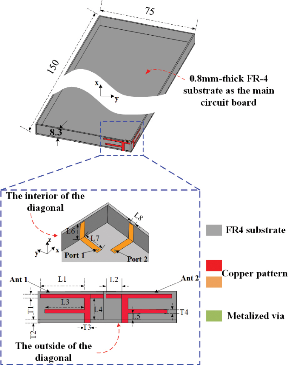
Figure 1: Geometry of the realized antenna pair.
Table 1: Parameters dimension of the design
| Parameters | Value, mm | Parameters | Value, mm |
|---|---|---|---|
| L1 | 16 | L7 | 8 |
| L2 | 4.4 | L8 | 2 |
| L3 | 13 | T1 | 1 |
| L4 | 5.7 | T2 | 0.8 |
| L5 | 1.7 | T3 | 2 |
| L6 | 7 | T4 | 1 |
2.1 Structure of the antenna pair
For the proposed eight-port MIMO antenna, the study designed an antenna pair firstly as shown in Fig. 1. The proposed antenna pair was simulated using the full-wave simulation software HFSS version 2020, and it was simulated based on the high precision solution of automatic mesh generation technology.The optimal dimensions for each single antenna element are summarized in Table 1. The size of the system ground plane was , typical for the dimension of a 5.3-inch handset,and four dielectric substrates (dielectric constant is 4.4, loss tangent is 0.02) are placed vertically around the system ground as borders, and the thickness of all dielectric substrates was 0.8 mm. As shown in Fig. 1, a pair of F-type monopole structures (red) was etched outside the dielectric substrate, and the feeder (orange) was etched inside. The antenna pair was placed orthogonally on the corner of the border, and the length of the longer side above was 16 mm, and the length of the shorter side below was 13 mm. The F-type monopole was fed by the microstrip feedline (while connecting to 50 SMA connectors when measuring.) to make the antenna work at 4.9 GHz.
Configurations and S-parameter ( and ) results of the F-type antenna pair without the NL and the final design are illustrated and compared in Figs. 2 (a)-(b), respectively. We can see that the resonant frequency of the antenna pair at 4.9 GHz () from the results obtained shown in Fig. 2 (a), and the isolation is 14 dB. From what we know, the above performance can meet the general requirement of smartphone MIMO antennas. Based on the above structure, we made a further attempt, that is, a NL was introduced between the two antenna elements as shown in Fig. 2 (b). We can observe that the resonant frequency and bandwidth of the antenna pair did not change, but the isolation of the antenna is 17 dB, which is a reduction of 3 dBi. Therefore, we finally adopted the second structure.
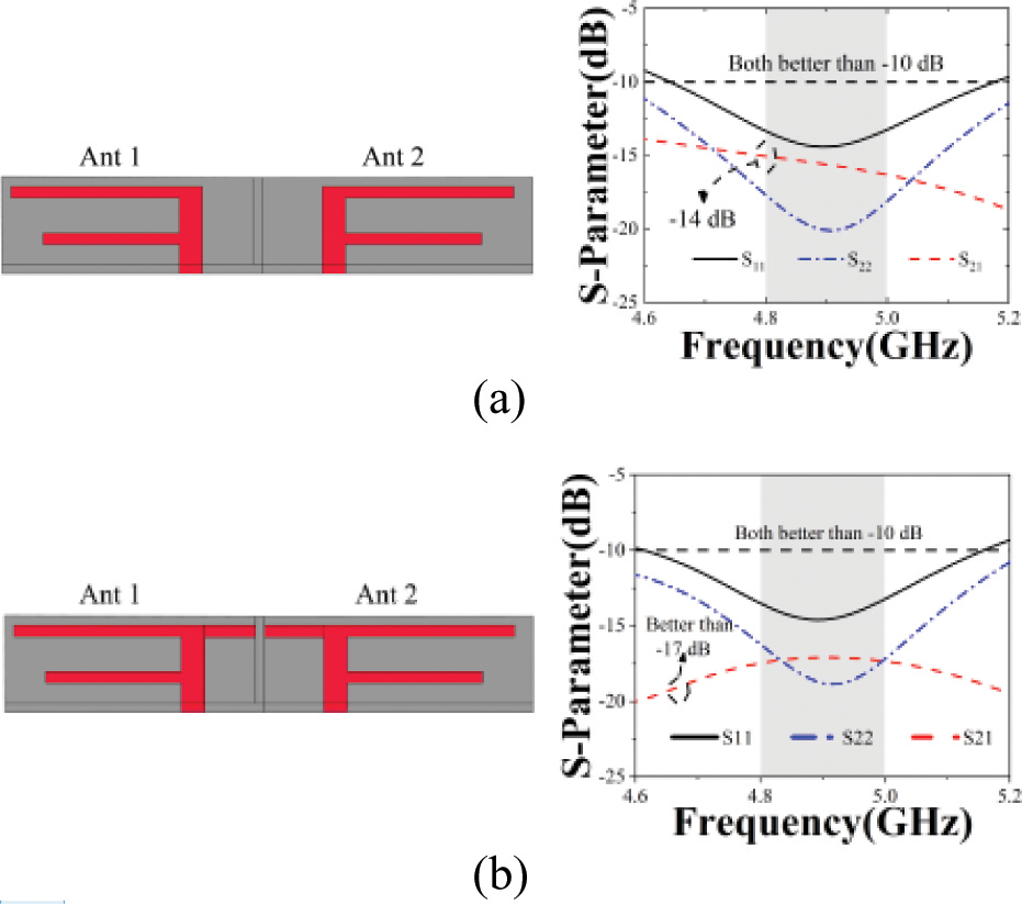
Figure 2: Different configurations and S-parameter for the antenna design with (a) without the NL, (b) the proposed.
2.2 Parameter analysis
In the process of antenna design, the parameter scan is usually performed to select the most suitable parameter. Here, two scanned parameters were set up to determine the most suitable parameter by analyzing the S-parameter in Figs. 3 (a)-(b).
Figure 3 (a) investigates the effects of the long side () of F-type monopoles on the operation band. We can see from Fig. 3 (a), when its size changes from 13 to 19 mm. The resonant frequency of the design varies from 5.5 to 4.5 GHz. When =16 mm, the resonant frequency is 4.9 GHz. It can be also affected by changing the short side () of the F-type monopole. As shown Fig. 3 (b), the resonant frequency tunes to lower or upper frequencies with the change of. When =13 mm, the resonant frequency is at 4.9 GHz. Therefore, =16 mm and =13 mm are selected to the final design.
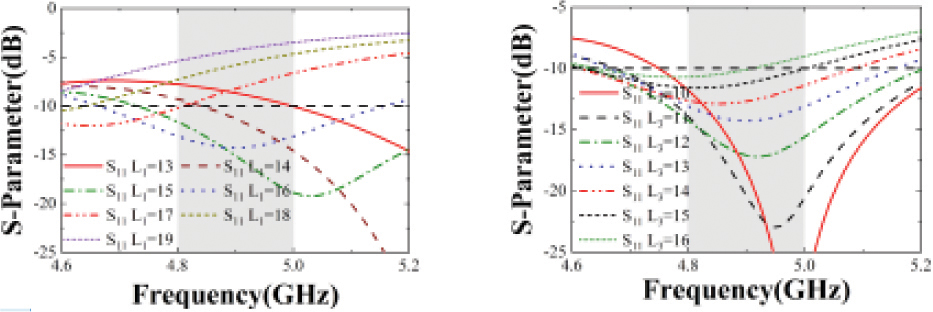
Figure 3: Simulated results of the proposed antenna for different values. (a) S-parameter for different (b) S-parameter for different .
2.3 Performance of the antenna pair
The simulated results of the final proposed F-type antenna pair are presented in Fig. 4 (a)-(c), respectively. The S-parameter is shown in Fig. 4 (a). The reflection coefficients of both antennas are better than 10 dB across the desired sub-6 GHz band (4.8-5 GHz). Owing to the layout of the antenna elements being orthogonal to each other, the antenna elements are orthogonally polarized and can only sense the weak signal sent by each other. Therefore, an excellent isolation level is achieved: better than 17 dB across the operation band.
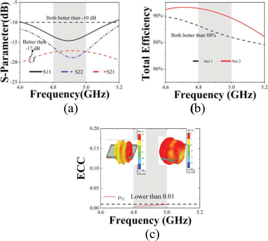
Figure 4: Simulated performance of the dual antenna pair. (a) S-parameters. (b) Total efficiency. (c) ECC. Inserts: realized gain patterns at 4.9 GHz.
Figure 4 (b) shows the TE of the antenna pair. Across the operation band, the efficiency ranges of Ant 1 and Ant 2 are both better than 88%, which achieved greatly high.
Figure 4 (c) shows the simulated ECC, which is the dot product of the two antennas’ complex radiation patterns. ECC is also a measurement of how tightly coupled antenna elements are, and it is calculated by ANSYS HFSS simulation software. The acceptable ECC criterion for MIMO antenna is less than 0.5. The simulated ECC is less than 0.01 across the operation band, indicating that the proposed antenna pair is with excellent diversity performance. Realized radiation patterns at 4.9 GHz of the two antennas are shown in the insets. Benefiting from orthogonal polarization, the main lobes of the two patterns are nearly orthogonal: Ant 1’s main lobe points to +x, y-direction; while Ant 2’s main beam points to –x-direction. Therefore, an extremely low ECC is achieved.
The resonance mechanism is derived from the one-half wavelength working mode realized by the folding of the monopole arm. Figure 5 (a) shows the current distribution when port 1 is excited and port 2 terminal is terminated to 50 . The upper and lower arms of the F-type monopole are used to generate resonance at 4.9 GHz, and the electric length can be observed to be about one-half wavelength. Other parts are used to complete impedance matching. Figure 5 (b) shows the electric field distribution of the antenna pair. When port 1 is excited, little current is registered on port 2, which is also the reason for the high isolation between antennas.
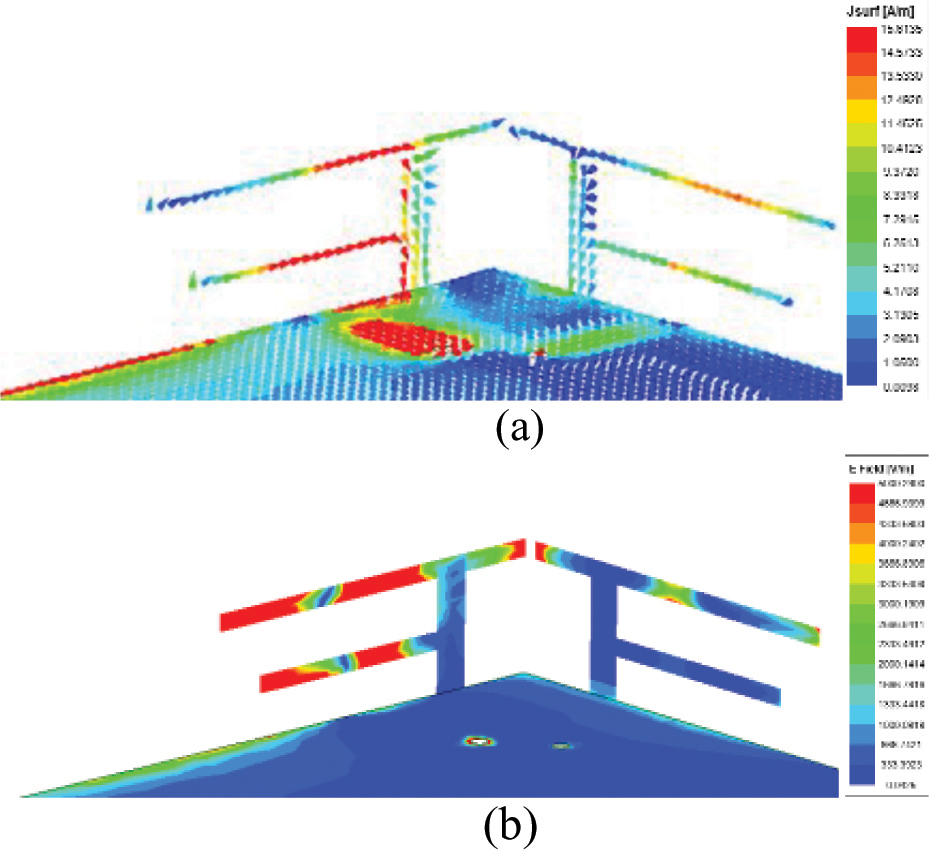
Figure 5: Field distributions at 4.9 GHz. (a) Vector current distribution, (b) Mag E-field distribution.
3 EIGHT-PORT ANTENNA
3.1 Eight-port antenna performance
The last part effectively verifies the feasibility of the antenna pair. On the above basis, the MIMO antenna system is constructed by placing four reciprocally symmetric F-type monopole antenna pairs at four diagonal of the smartphone, and grounded slots on short sides to improve isolation, as shown in Fig. 6 (a). An FR-4 substrate is employed as the main board of the smartphone. A metal ground plane is printed at the back side of the FR-4 substrate. Four FR-4 substrates are vertically placed around the ground plane to imitate the rim of the smartphone. A prototype was fabricated to demonstrate the feasibility of the proposed , MIMO antenna in the experiment, and its side, front and back photographs are depicted in Fig. 6 (b). Each antenna element is fed by a 50 microstrip feed line that is directly connected to a 50 Sub-Miniature-A (SMA) connector via the system ground.

Figure 6: (a) Simulated, (b) Prototyped photographs of MIMO antenna.
Before forming the eight-port antenna, we made some improvements when forming the four-port antenna. As shown in Fig. 7, when there is no slot on the ground, the isolation between the two antenna pairs on the short side is low as shown in Fig. 7 (a). When we etched the appropriate grounded slot on the short side of the ground, the isolation dropped to 16 dB and showed better performance.
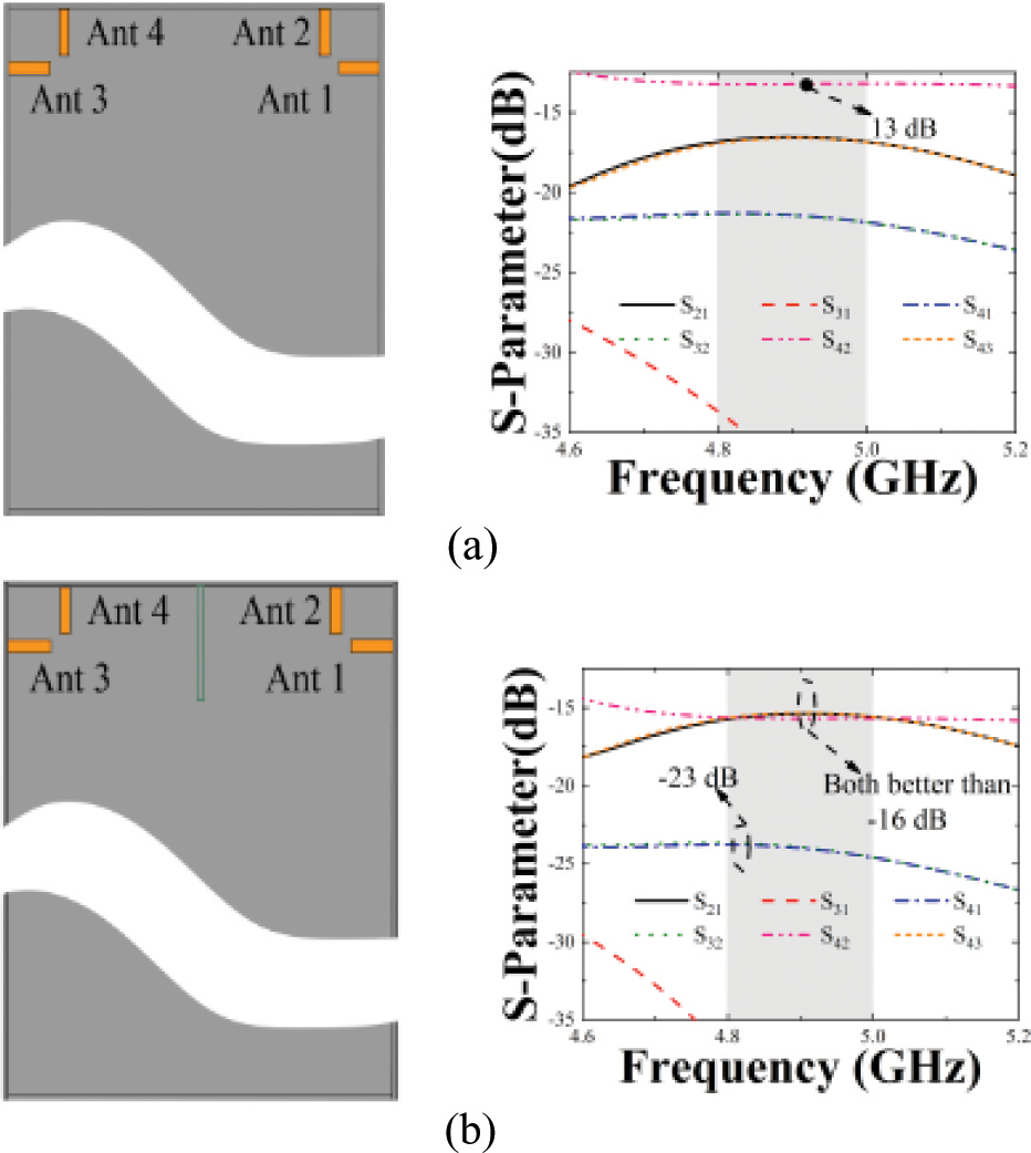
Figure 7: Isolation performance of the four-port antenna structure (a) Without grounded slot, (b) With grounded slot.
In the eight-port MIMO antenna, as shown in Fig. 8, it can also be seen from the three-dimensional (3-D) patterns that there is a pattern diversity phenomenon when port 1, port 2, port 3, and port 4 are excited respectively (the radiation patterns of the remaining four antennas are symmetrical with above ports due to symmetry). When port 1 or port 3 is excited, the radiation direction is the x direction, and when port 2 or port 4 is excited, the radiation direction is the +x and +z direction. The maximum radiation direction of each antenna unit does not overlap. The radiation direction is different when the antenna is excited separately, and this further illustrates the high isolation performance. In addition, the two-dimensional (2-D) radiation patterns of the four ports at 4.9 GHz are also shown in Fig. 8, the maximum gains of the four ports point in different directions, which also can explain the good isolation and low ECC.
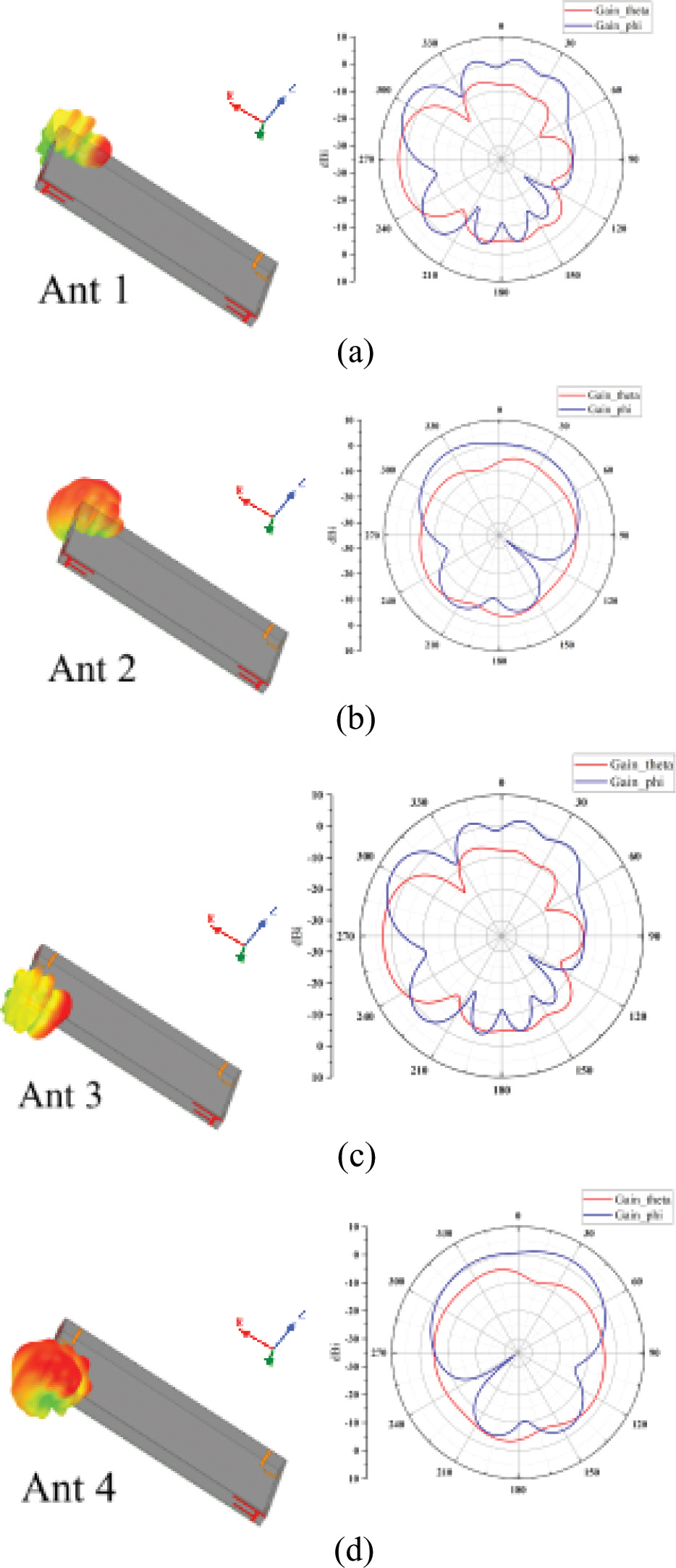
Figure 8: 3-D and 2-D radiation patterns at 4.9 GHz from (a) Port 1, 2-D pattern in plane, (b) Port 2, 2-D pattern in plane, (c) Port 3, 2-D pattern in plane, (d) Port 4, 2-D pattern in plane.
In this section, the performance of the proposed eight-port MIMO antenna is also analyzed and the measured results are compared to the simulated ones. Figure 9 is the test procedure for the antenna prototype using the Agilent E5071C vector network measurement analyzer. Figure 10 shows the simulated and measured results respectively.
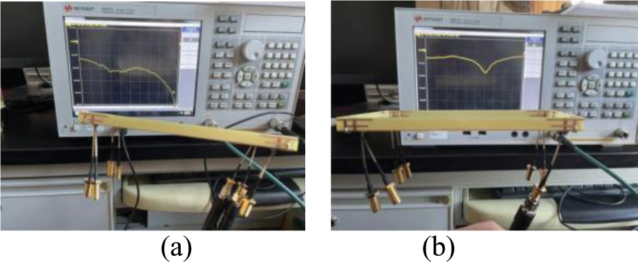
Figure 9: Photos of the test procedure. (a) Single-port. (b) Dual-port.
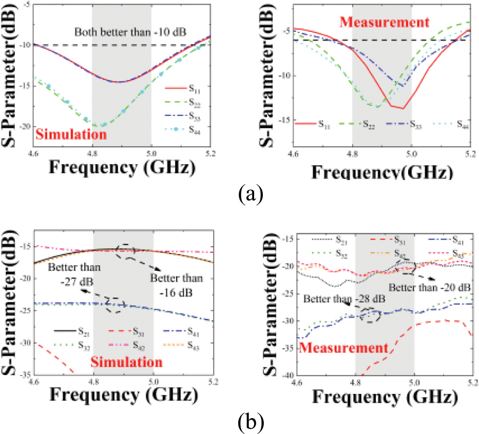
Figure 10: Simulated and measured results of the eight-antenna MIMO array (a) reflection coefficient, (b) isolation.
Table 2: Contrast of the referenced and proposed
| Ref | Decoupling Method | Working Band (GHz) | Isolation (dB) | TE (%) | ECC | Complexity |
| [1] | Distance optimization | - | Simple | |||
| [2] | LC tank | – | - | Complex | ||
| [4] | Distance optimization | Simple | ||||
| [6] | Orthogonal polarization | Medium | ||||
| [7] | Orthogonal Polarization & NL | 4.8-6 | Simple | |||
| [8] | DGS & NL | ¡- | Simple | |||
| [9] | DGS | Simple | ||||
| [14] | Asymmetrically Mirrored | Medium | ||||
| [18] | Self-decoupled | Medium | ||||
| [20] | Self-decoupled | - | Complex | |||
| [22] | Shorting Stub | - | Medium | |||
| Proposed | Orthogonal Polarization | Simple |
As the structure is symmetrical in terms of placement of the orthogonal pairs, only port 1, port 2, port 3, and port 4 are discussed in this section. The results for the S-parameter in relation to port 5–port 8 are omitted. Figure 10 (a) shows the simulated and measured for port 1, port 2, port 3, and port 4. A resonant response is achieved at 4.9 GHz. Although some slight discrepancies can be observed due to minor production and welding errors, the measured results agree with the simulated ones covering well the bands of interest. In Fig. 10 (b), the measured is compared to the simulated one. The worst is less than 16 dB by connecting the orthogonal antennas with an NL and etching grounded slots between antenna pairs. Since the matching degree of test data in Fig. 10 (a) is worse than simulation data, the test data is better than the simulation data for isolation performance, which is at the expense of resonant characteristics.
3.2 MIMO performance
This part gives the MIMO performance index of this design from the TE and ECC.
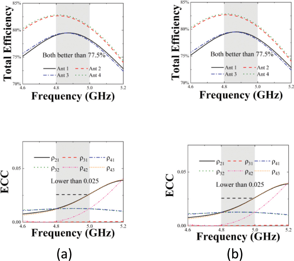
Figure 11: (a) Total efficiency, (b) ECC.
The TE of port 1, port 2, port 3 and port 4 in eight-port MIMO antenna are shown in Fig. 11 (a). The total efficiency of antenna 2 and antenna 4 is the same: 80% 83%, and the total efficiency of antenna 1 and antenna 3 is the same: 77.5% 79%. Overall, the total efficiency achieved by port 1, port 2, port 3, and port 4 is high and desirable.
Figure 11 (b) shows ECC curves between two pairs of antenna pairs. It can be seen from the figure that ECC between any two elements is less than 0.025, the smartphone antenna requires ECC of less than 0.5, so the proposed antenna in this paper meets the requirement.
Table 2 exhibits the comparison of the proposed antenna with the references. Compared to the references, it can draw a conclusion that the designed antenna performs better isolation (better than 16 dB), excellent ECC (low than 0.025), and good total efficiency (high than 77.5%). In addition, due to print on the corner of the smartphone border, the designed antenna leaves much space for other types of antennas and is an eligible candidate for a 5G full-screen smartphone.
4 CONCLUSION
In this letter, a new design of an eight-port diagonal MIMO antenna with a compact size and simple structure is designed to operate in 4.8-5 GHz for 5G smartphone applications. Isolation between the orthogonal antenna elements better than 16 dB and it is improved due to the addition of an NL and grounded slot. A good ECC of less than 0.025 is obtained and total efficiency is better than 77.5%.
ACKNOWLEDGMENT
The authors extend appreciation to the support of the National Natural Science Foundation of China (Grant No. 51965047), the Natural Science Foundation of Inner Mongolia (Grant No. 2021MS06012), and the Key Scientific and Technological Project of Inner Mongolia (Grant No. 2020GG0185) for this project.
REFERENCES
[1] K. L. Wong and J. Y. Lu, “10-antenna array in the smartphone for 3.6-GHz,” Microwave Opt. Technol. Lett., vol. 57, pp. 1699-1704, 2015.
[2] K. L. Wong, H. J. Chang, and W. Y. Li, “Integrated triple-wideband triple-inverted-F antenna covering 617-960/1710-2690/3300-4200 MHz for 4G/5G communications in the smartphone,” Microwave and Optical Technology Letters, vol. 60, no. 9, pp. 2091-2096, 2018.
[3] Q. Chen, H. Lin, J. Wang, L. Ge, Y. Li, T. Pei, and C. -Y. -D. Sim, “Single ring slot-based antennas for metal-rimmed 4G/5G smartphones,” IEEE Transactions on Antennas and Propagation, vol. 67, no. 3, pp. 1476-1487, 2019.
[4] X. Zhang, Y. Li, W. Wang, and W. Shen, “Ultra-wideband 8-Port MIMO antenna array for 5G metal-frame smartphones,” IEEE Access, vol. 7, pp. 72273-72282, 2019.
[5] A. Diallo, C. Luxey, P. Le Thuc, R. Staraj, and G. Kossiavas, “Study and reduction of the mutual coupling between two mobile phone PIFAs operating in the DCS1800 and UMTS bands,” IEEE Transactions on Antennas and Propagation, vol. 54, no. 11, pp. 3063-3074, 2006.
[6] L. Sun, H. Feng, Y. Li, and Z. Zhang, “Compact 5G MIMO mobile phone antennas with tightly arranged orthogonal-mode pairs,” IEEE Transactions on Antennas and Propagation, vol. 66, no. 11, pp. 6364-6369, 2018.
[7] D. Serghiou, M. Khalily, V. Singh, A. Araghi, and R. Tafazolli, “Sub-6 GHz dual-band 8 8 MIMO antenna for 5G smartphones,” IEEE Antennas and Wireless Propagation Letters, vol. 19, no. 9, pp. 1546-1550, 2020.
[8] W. Jiang, B. Liu, Y. Cui, and W. Hu, “High-isolation eight-element MIMO array for 5G smartphone applications,” IEEE Access, vol. 7, pp. 34104-34112, 2019.
[9] X. T. Yuan, W. He, K. D. Hong, C. Z. Han, Z. Chen, and T. Yuan, “Ultra-wideband MIMO antenna system with high element-isolation for 5G smartphone application,” IEEE Access, vol. 8, pp. 56281-56289, 2020.
[10] X. T. Yuan, X. J. Wu, Z. Chen, C. Z. Han, X. Zhang, and T. Yuan, “Wideband 8-antenna array with high isolation for Sub-6 GHz MIMO applications,” 2020 9 Asia-Pacific Conference on Antennas and Propagation (APCAP), PP. 1-2, 2020.
[11] Y. Hei, J. He, and W. Li, “Wideband decoupled 8-element MIMO antenna for 5G mobile terminal applications,” IEEE Antennas and Wireless Propagation Letters, vol. 20, no. 8, pp. 1448-1452, 2021.
[12] W. Jiang, Y. Cui, B. Liu, W. Hu, and Y. Xi, “A dual-band MIMO antenna with enhanced isolation for 5G smartphone applications,” IEEE Access, vol. 7, pp. 112554-112563, 2019.
[13] Z. Ren, A. Zhao, and S. Wu, “MIMO antenna with compact decoupled antenna pairs for 5G mobile terminals,” IEEE Antennas and Wireless Propagation Letters, vol. 18, no. 7, pp. 1367-1371, 2019.
[14] K. L. Wong, C. Y. Tsai, and J. Y. Lu, “Two asymmetrically mirrored gap-coupled loop antennas as a compact building block for eight-antenna MIMO array in the future smartphone,” IEEE Transactions on Antennas and Propagation, vol. 65, no. 4, pp. 1765-1778, 2017.
[15] K. L. Wong, Y. H. Chen, and W. Y. Li, “Conjoined ultra-wideband (2,300-6,000 MHz) dual antennas for LTE HB/WiFi/5G multi-input multi-output operation in the fifth-generation tablet device,” Microwave and Optical Technology Letters, vol. 61, no. 8, pp. 1958-1963, 2019.
[16] A. Zhao and Z. Ren, “Size reduction of self-isolated MIMO antenna system for 5G mobile phone applications,” IEEE Antennas and Wireless Propagation Letters, vol. 18, no. 1, pp. 152-156, 2019.
[17] F. Ghawbar, A. S. Jumadi, H. A. Majid, F. A. Saparudin, A. S. A. Ghafar, and B. A. F Esmail, “Compact self-isolated MIMO antenna system with low mutual coupling for 5G mobile applications,” 2020 IEEE Student Conference on Research and Development (SCOReD), pp. 200-205, 2020.
[18] L. Sun, Y. Li, Z. Zhang, and H. Wang, “Self-decoupled MIMO antenna pair with shared radiator for 5G smartphones,” IEEE Transactions on Antennas and Propagation, vol. 68, no. 5, pp. 3423-3432, 2020.
[19] L. Sun, Y. Li, and Z. Zhang, “Wideband decoupling of integrated slot antenna pairs for 5G smartphones,” IEEE Transactions on Antennas and Propagation, vol. 69, no. 4, pp. 2386-2391, 2021.
[20] B. Yang, Y. Xu, F. Lu, R. Li, L. Zhang, and Y. Liu, “High-isolation dual-port antenna with self-decoupling characteristics for 5G smartphone applications,” International Journal of RF and Microwave Computer-Aided Engineering, vol. 31, no. 8, 2021.
[21] L. Y. Nie, X. Q. Lin, S. Xiang, B. Wang, L. Xiao, and J. Y. Ye, “High-isolation Two-port UWB antenna based on shared structure,” IEEE Transactions on Antennas and Propagation, vol. 68, no. 12, pp. 8186-8191, 2020.
[22] X. T. Yuan, Z. Chen, T. Gu, and T. Yuan, “A wideband PIFA-pair-based MIMO antenna for 5G smartphones,” IEEE Antennas and Wireless Propagation Letters, vol. 20, no. 3, pp. 371-375,2021.
[23] L. Chang, Y. Yu, K. Wei, and H. Wang, “Orthogonally polarized dual antenna pair with high isolation and balanced high performance for 5G MIMO smartphone,” IEEE Transactions on Antennas and Propagation, vol. 68, no. 5, pp. 3487-3495,2020.
BIOGRAPHIES

Rui Shao received a bachelor’s degree in communication engineering from Shandong University of Technology,Zibo, China, in July 2020. From September 2020, she studies for the master’s degree of Information and Communication Engineering at Inner Mongolia University, Hohhot, China. Her research interests include research and design of 5G high isolation MIMO antenna.

Junlin Wang received a doctor’s degree in engineering in Instrument Science and Technology of Zhong-bei University. He is currently working in the College of Electronic Information Engineering, Inner Mongolia University, Hohhot, China. His research interests include micro-nano RF devices (antennas, filters, couplers, etc.) and metamaterial antennas.

Xin Wang received a Ph.D. in engineering in Instrument Science and technology from Zhong-bei University, she is currently working in the College of Electronic Information Engineering, Inner Mongolia University, Hohhot. China. Her research interests include micro-nano RF devices (antennas, filters, couplers, etc.) and metamaterial antenna.

Yonghao Wang received his bachelor’s degree in Communication Engineering from Shandong University of Science and Technology in Qingdao, China in July 2020. Since September 2020, he is studying for a master’s degree in Electronic and Communication Engineering at Inner Mongolia University, Hohhot, China. His research interests include research and design of 5G miniaturized high isolation dual-band MIMO antennas for mobile phones.
ACES JOURNAL, Vol. 37, No. 8, 867–874.
doi: 10.13052/2022.ACES.J.370805
© 2022 River Publishers