On Controlling the Passband and Stopband of UWB Band-Pass Filter
Tamer G. Abouelnaga1,2 and Esmat A. Abdallah1
1Microstrip Circuits Department, Electronics Research Institute ERI, Cairo, Egypt
2Electrical Engineering Department, Higher Institute of Engineering and Technology HIET, Kafr Elsheikh, Egypt
Tamer@eri.sci.eg
Submitted On: January 24, 2022; Accepted On: September 11, 2022
Abstract
In this article, the passband, and stopband of quarter wavelength stubs-based Band Pass Filter (BPF) are controlled by a straightforward and new method. This method depends on inserting an attenuation pole and tuning the passband by a Circular Slot Ring Resonator (CSRR) and rectangular slot beneath the BPF’s stubs. Hence, controlling the passband width without any further area usage is achieved. The stop-band rejection level and bandwidth are controlled by inserting Band Stop Filter (BSF) after the BPF such that the used rectangular slots beneath the stubs control the stop-band bandwidth. For verification, third-order Chebyshev BPF and Butterworth BSF filters are used. The proposed filter passband is chosen to cover the sub-6 GHz different 5G bands. The proposed BPF has an ultra-wide 3 dB passband of 2.97 GHz (2.35 GHz-5.32 GHz) and a 20 dB stopband of 4.59 GHz (6.18-10.77 GHz). The proposed BPF filter is fabricated, measured, and the results are in good agreement with their simulated counterparts.
Index Terms: 5G, attenuation poles, Butterworth BSF, Chebyshev BPF, UWB.
1 INTRODUCTION
In many wireless communication systems, conventional microstrip Band Pass Filters (BPFs) are used due to their planar structure and ease of fabrication. For ultrawideband applications, a Short-circuited stub Band Pass Filter (SBPF) may be a good candidate filter. Control of attenuation pole frequency of a BPF near the cutoff frequency results in a sharp rate of cutoff. The closer the attenuation poles to the cut-off frequency, the sharper the filter skirt, and the higher the selectivity. A lot of research had been done to control the passband width and achieve a sharp cutoff rate. In [1], two open stubs were proposed to control the attenuation pole frequency of a dual-mode circular microstrip ring resonator bandpass filter, keeping the bandwidth almost constant. In [2], a modified Chebyshev BPF with attenuation poles in the stopband was proposed. The insertion of attenuation poles was accomplished by connecting a lumped inductor or capacitor in series with a shunt-type coaxial transmission-line resonator. In [3], a fifth-order combline filter with two attenuation poles (transmission zeros) was proposed. The attenuation poles were controlled by dedicated resonators, which were coupled to non-resonating nodes.
In [4], UWB bandpass using ring filter was introduced. The ring filter was made to control the attenuation pole frequency by adjusting both the ring and the stub impedance.
In [5], a wideband BPF was constructed of two sections of three coupled lines separated by a nonuniform line resonator. One transmission zero was introduced at each edge of the desired passband, and one of the outer coupled lines of each section was shorted to the ground. The nonuniform resonator was constructed by attaching pair of capacitive open-ended stubs at its central location. Insertion of attenuation poles in all aforementioned BPFs needs more area and their development is somewhat difficult.
Also, an unwanted harmonic passband is observed at approximately three times the passband mid-band frequency, which is unsuitable for wireless receiver circuitry, and hence, suppression of spurious signals of the upper stopband is essential to be wide as possible [6].
To meet this requirement, various methods have been proposed [7–14]. In [7], stepped-impedance open stubs were added to the resonator ports to add another transmission zero to suppress the second harmonic frequency. Although, it had the advantages of size reduction, simplicity, and low cost. But it suffers from extra insertion loss and a 5.2 dB rejection level. In [8], an ultra-wideband microstrip BPF was obtained using two parallel coupled lines resonators centered by a T-inverted shape. This filter suffers from critical dimensions of 0.2 mm which will limit the power handling capability of the proposed filter. In [9], a metamaterial-based resonator was used to obtain a BPF. This filter had the advantages of size reduction and low cost, but it suffers from extra insertion loss and a 13 dB rejection level. In [10], suppression of spurious signals was done by a crown Band Stop Filter (BSF). This filter had good harmonic suppression, but its fractional bandwidth should be further increased. In [11], an ultra-wideband (UWB) microstrip band-pass filter was proposed by using the multi-mode resonator technique. The proposed structure was realized by three and two open and short stubs, respectively. This filter had good harmonic suppression, but its insertion loss should be decreased and suffers from critical dimensions of 0.1 mm which will lower its power capability. A dual Behaviour Resonator (DBR) filter was reported in [12]. BSF basic topology is used by interrupting the uniform transmission line with multiple unequal lengths of shunt stubs to enforce the emergence of dual passbands relying on multiple transmission zeros. This solution increases component count, circuit size, and power consumption. Also, it suffers from narrow fractional bandwidth.
In [13], to insert transmission zeros in the broadband filter, the coupling line was connected to a certain position on the resonator. Then the coupling strength was adjusted by the connecting position. This filter had good fractional bandwidth, but it suffered from extra insertion loss and a reduced rejection level of 5 dB. In [14], a cross-coupled line structure was used to obtain a broadband band-pass filter. Cross-coupled line structure was composed of parallel-coupled lines and an open stub. This filter had good insertion loss, but its fractional bandwidth should be further enhanced. In [15], an H-type sandwich slotline structure was employed to obtain the UWB passband filter. This filter had good fractional bandwidth, but its insertion loss and stopband rejection level should be further enhanced.
In this paper, any quarter-wavelength shorted stubs-based BPFs with any odd order could be used. The proposed method doesn’t need any lumped elements or parasitic elements to control the performance. Also, it is simple and promising since no additional area usage is required. It is mainly depending on Defected Ground Structure (DGS) structure. The insertion of an attenuation pole at the lower passband edge is achieved by adding CSRR at the middle short stub of the BPF. The attenuation pole frequency is controlled by the ring radius. The whole passband width is controlled by adding a rectangular slot beneath the shorted stubs. For verification, a third-order Chebyshev BPF is used. The upper stopband rejection level is achieved by cascading the proposed third-order BPF with third-order Butterworth open stubs BSF. The stopband width of the BSF is controlled by adding two rectangular slots beneath the connecting lines of the BSF. Finally, the proposed BPF filter is fabricated, measured, and the results are compared with their simulatedcounterparts.
2 DESIGN PROCEDURE OF THE PROPOSED HARMONIC SUPPRESSED BPF
In this section, the proposed BPF is obtained firstly, by designing, analyzing, and optimizing a third-order Chebyshev bandpass filter BPF. Then the middle stub is loaded by Circular Slot Ring Resonator CSRR for realizing the attenuation pole at the lower stopband and close to the lower cutoff frequency. Then, a rectangular slot is added to control the passband width of the proposed BPF. Secondly, a third-order Butterworth BSF is designed, analyzed, and optimized at the upper stopband of the proposed BPF. Hence, an upper stopband with at least a 20 dB rejection level is achieved. Finally, both BPF and BSF are cascaded, BSF stopband width is controlled by adding two stubs below its connecting lines, and the resultant filter performance is investigated. For the proposed BPF, different frequency bands of sub-6 GHz 5G are chosen to be covered by the passband of the proposed BPF. From the latest published version of the 3GPP technical standard (TS 38.101), the sub-6 GHz bands for the 5G communications are classified into new radio bands such as n53 (2.483 – 2.495), n77 (3.3 GHz– 4.2 GHz), n78 (3.3 GHz–3.8 GHz), and n79 (4.4 GHz–5 GHz) [16–17].
2.1 Proposed BPF
Third-order Chebyshev BPF is designed based on three shunt short-circuited stubs that are long with connecting lines that are also long, where is the guided wavelength at the mid-band frequency. CST Microwave Studio software is used for the simulation of different stages of the proposed filter. In this paper, the sub 6 GHz 5G frequency bands should be covered (2.4 GHz to 5 GHz). As a start, a three-pole Chebyshev short-circuited BPF centered at = 4.25 GHz with 58.8% fractional bandwidth (FBW), (3 GHz-5.5GHz), has been designed. This passband is chosen 600 MHz shifted forward and it will be shifted back through the fine-tuning process. For all the simulations FR-4 dielectric substrate is used, having a dielectric constant of 4.4, a thickness of 1.6 mm, and a loss tangent of 0.019. The design equations of short-circuited BPF, Fig. 1, can be found in equation 1 [18] as:
The characteristic admittance of the shunt stub:
The characteristic admittance of the connecting lines is calculated as:
where is the element value of a ladder-type Chebyshev lowpass prototype filter given for a normalized cutoff and is a dimensionless constant, which is assigned to a value that gives a convenient admittance level. For third-order BPF, Fig. 2 (a) shows the layout of the short-circuited BPF. For a passband ripple of 0.04321, the prototype parameters of the filter and the computed design widths and lengths are listed in Tables 1 and 2, respectively.
Table 1: The prototype parameters of the BPF
| 1 | 0.85154 | 1.10315 | 0.85154 | 1 |
Table 2: The prototype layout dimensions
| 1 | 25.3228 | 8.077 | 9.322 |
| 2 | 38.2373 | 4.544 | 8.914 |
| 3 | 25.3228 | 8.077 | 9.322 |
| 1 | 60.5 | 2.106 | 5.016 |
| 2 | 60.5 | 2.106 | 5.016 |
Table 3: Optimized dimensions of the BPF prototype
| 1 | 55.4889 | 2.472 | 9.322 |
| 2 | 39.5408 | 4.32 | 8.914 |
| 3 | 55.4889 | 2.472 | 9.322 |
| 1 | 49.4884 | 3.018 | 5.016 |
| 2 | 49.4884 | 3.018 | 5.016 |
The width of the 50 ohms microstrip line is 2.752 mm. The conventional BPF layout, 3D geometry, and S-parameters are shown in Fig. 2 (b). The dimensions of the BPF that are given in Table 2 are simulated by CST and the obtained matching level and insertion loss are 4.2 dB and 2.6 dB, respectively at 3.6 GHz which indeed needs a geometry optimization process. Table 3 shows the optimized dimensions and Fig. 3 (b) shows the S-parameters of the optimized BPF. From Fig. 3 (b), the 10 dB passband extends from 2.65 GHz to 5.5 GHz with an insertion loss of 0.5 dB at the mid of the passband. The upper stopband rejection level degrades much at 7.7 GHz and further frequencies. Also, the n53 frequency band isn’t covered and the lower stopband rejection level is at 5 dB at 2 GHz. To solve these problems, firstly, an attenuation pole at 2.4 GHz should be inserted.
2.2 Insertion of an attenuation pole at 2.4 GHz
The Circular Slot Ring Resonator CSRR when placed and centered at the edge of the middle-shorted stub of the BPF will act as a stopband filter at the desirable frequency that is related to its dimensions. The CSRR BSF performance is investigated in Fig. 3 (a) where the same BPF dimensions are used. The effect of changing CSRR inner radius is investigated, keeping the slot width at 0.6 mm. Figure 3 (a) shows that increasing the inner CSRR radius from 3 mm to 6 mm will decrease the stopband frequency from 3.36 GHz to 1.85 GHz. This wide range of frequencies will add a new freedom degree to the designing process. Empirical equation 2 describes the relationship between the inner radius in mm and the stopband frequency in GHz as as:
| (2) |
Based on Fig. 3 (a), inner and outer radii of 4 mm and 4.6 mm, respectively are chosen for 2.4 GHz CSRR BSF. Hence, an attenuation pole frequency of 2.4 GHz and rejection level of 50 dB is presented. Figure 3 (b) shows the S-parameters of the proposed BPF which is loaded with the CSRR. The passband extends from 3.23 GHz to 5.57 GHz with a lower rejection level of 50 dB at 2.4 GHz and a lower cutoff frequency of 2.89 GHz which gives a sharp filter skirt, and good selectivity at the lower passband edge. The loaded BPF still suffers from a low rejection level at the upper stopband starting from 8 GHz and further frequencies. Also, the n53 band is not covered yet by the 10 dB passband. Adding a rectangular slot just below the three shorted stubs of the proposed BPF will control the passband width since it will directly affect the electrical length of the three shorted stubs[19–20].
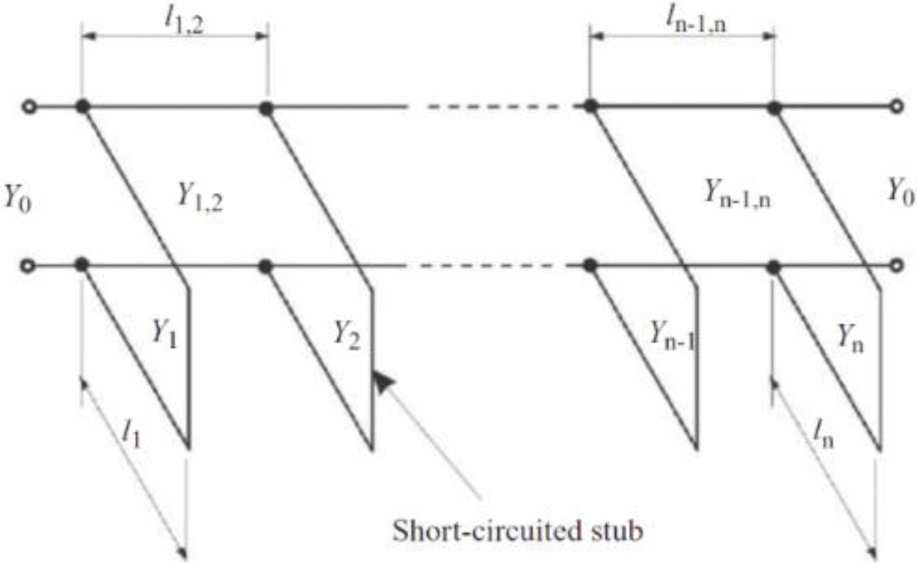
Figure 1: Transmission line BPF with quarter-wavelength short-circuited stubs.
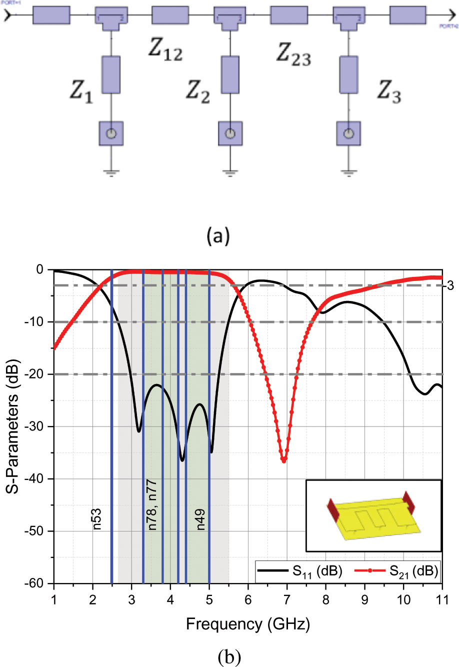
Figure 2: Conventional short-circuited BPF (a) layout and (b) simulated S-parameters.
2.3 Controlling the passband width of the BPF
The rectangular slot’s length effect on the 3 dB passband is investigated in Fig. 4 (a) where the slot width is kept at 1 mm and centered at 6.43 mm from the shorted middle stub edge of the proposed BPF. As predicted by Fig. 4 (a), the lower cutoff frequency is decreased as the slot length is increased. The empirical equations 3 and 4 describe the upper 3 dB frequency in GHz and the lower 3 dB frequency in GHz as slot length ranges from 8 mm to 20 mm as:
| (3) |
| (4) |
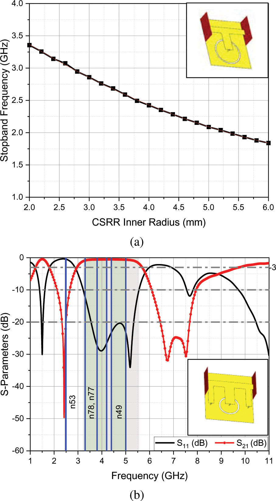
Figure 3: (a) CSRR BSF frequency versus inner radius. (b) Proposed BPF loaded with CSRR S-parameters.
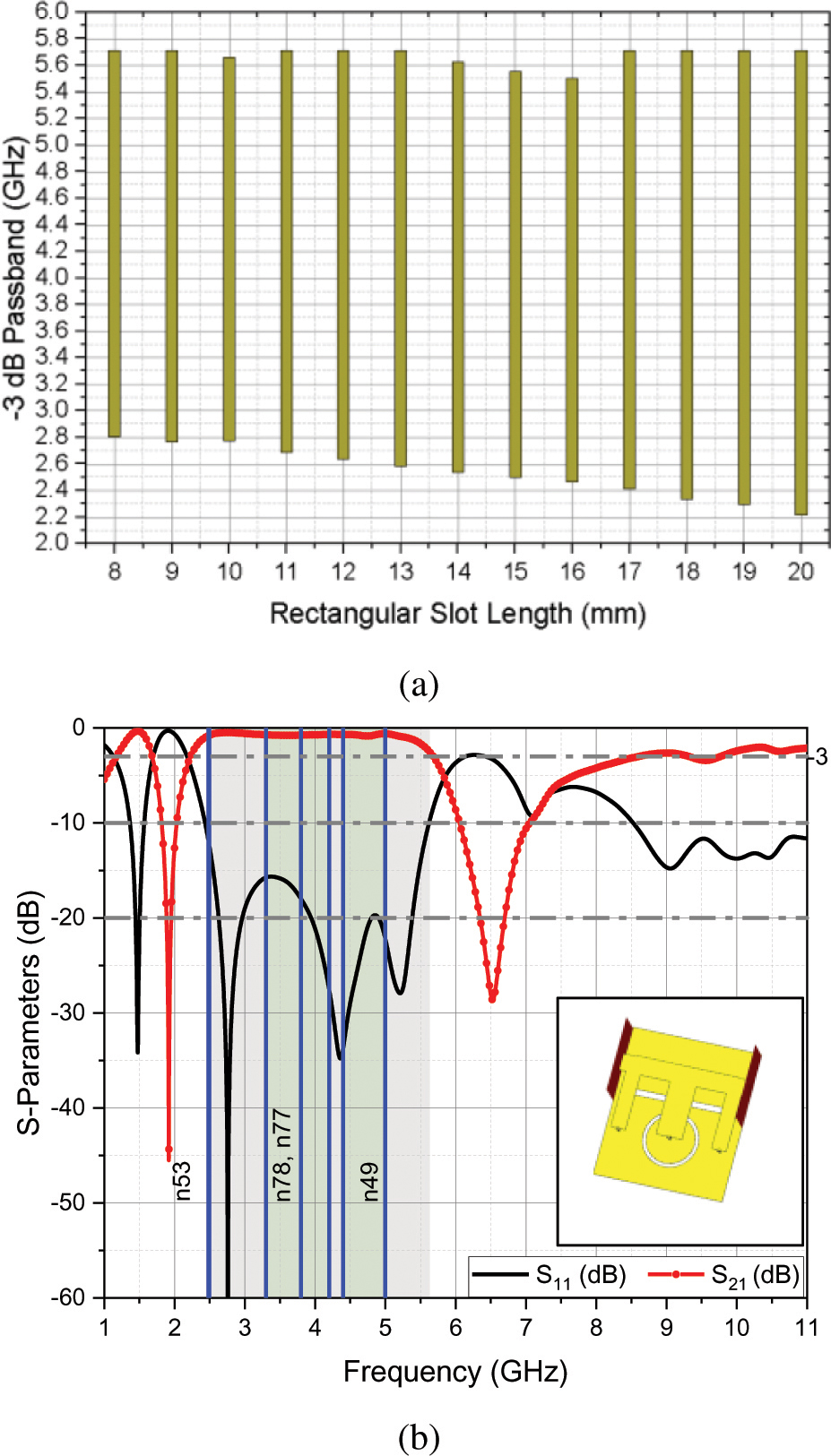
Figure 4: Proposed BPF loaded with CSRR (a) rectangular slot length effect and (b) S-parameters.
Table 4: Third-order Butterworth lowpass filter parameters with 3dB attenuation
| 1 | 1 | 2 | 1 | 1 |
A slot length of 20 mm is the best choice to obtain a 3 dB passband range which extends from 2.22 GHz to 5.71 GHz as shown in Fig. 4 (a). It can be noticed that the n53 band is covered by the proposed BPF by the 10 dB passband, Fig. 4 (b). From Fig. 4 (b), the spurious 3 dB passband is observed at 8.5 GHz to 11GHz and further. The spurious response should be eliminated to avoid passband interference. Hence, in the next section, a third-order bandstop Butterworth filter will be designed and then the proposed BPF is cascaded with it. This combination achieves a wide stopband, high rejection level, and low insertion loss.
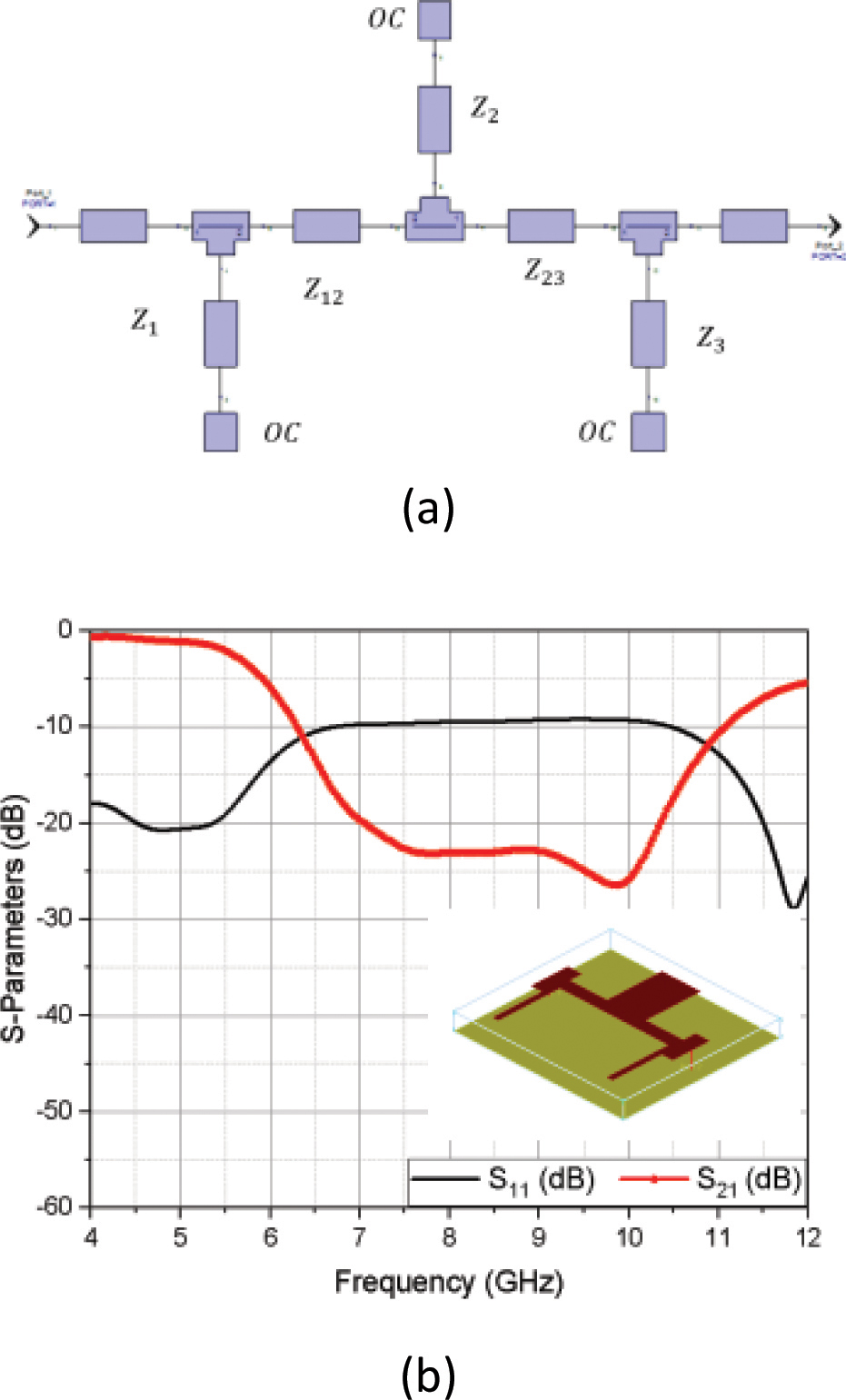
Figure 5: Third-order optimized Butterworth Open-circuited BSF (a) layout and (b) S-parameters.
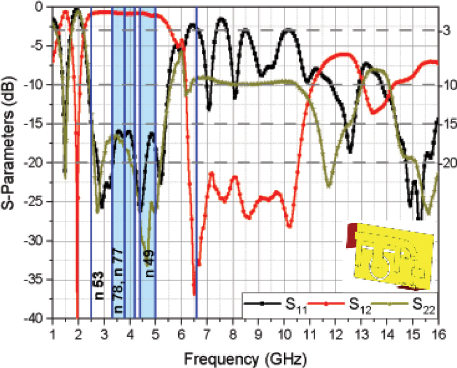
Figure 6: Proposed BPF simulated S-parameters.
Table 5: Third-order Butterworth BSF dimensions
| 1 | 135.709 | 0.214 | 3.981 |
| 2 | 43.4559 | 3.732 | 4.446 |
| 3 | 135.709 | 0.214 | 3.981 |
| 1 | 78.304 | 1.224 | 2.852 |
| 2 | 78.304 | 1.224 | 2.852 |
Table 6: Optimized dimensions of Butterworth BSF
| 1 | 113.346 | 0.43 | 3.981 |
| 2 | 48.7056 | 3.1 | 4.446 |
| 3 | 113.346 | 0.43 | 3.981 |
| 1 | 86.1602 | 0.969 | 2.852 |
| 2 | 86.1602 | 0.969 | 2.852 |
2.4 BSF design and analysis
Butterworth BSF was chosen to reject the harmonics in the frequency band that extends from 6 GHz to 12 GHz with a mid-stopband frequency of 9 GHz. The BSF was developed using three shunt quarter-wavelength open stubs with two pairs of symmetrical connecting microstrip lines that are quarter-wavelength long at the mid-stopband frequency. The design procedure started with a chosen ladder-type Butterworth lowpass prototype of order three,Table 4.
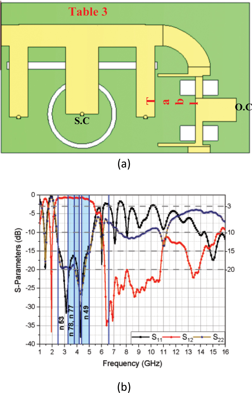
Figure 7: Proposed extended upper stopband BPF (a) geometry and (b) simulated S-parameters.
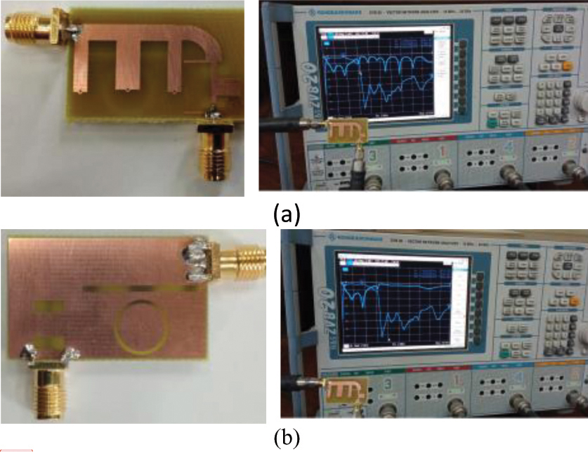
Figure 8: Fabricated prototype of the proposed BPF (a) top view and (b) bottom view.
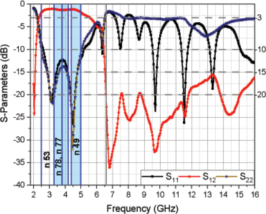
Figure 9: Proposed BPF measured S-parameters.
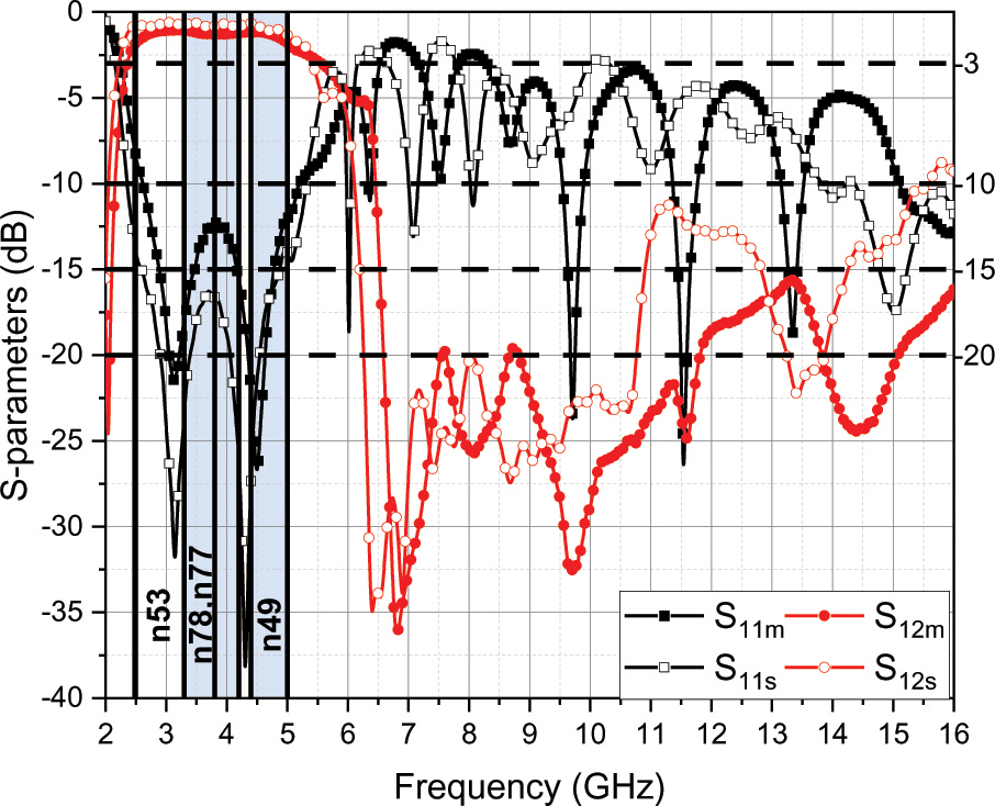
Figure 10: Proposed BPF measured and simulated S-parameters.
The design equations for the third-order filter can be found in [13]. The BSF layout is shown in Fig. 5 (a). Table 5 shows the layout dimensions of the BSF. A rejection of 4.5 dB is obtained at the lower edge of the stopband (6 GHz). An optimization process was needed to enhance the lower stopband edge rejection. Table 6 shows the optimized dimensions of the BSF. Figure 5 (b) shows the optimized S-parameters results where the lower bandstop edge (6 GHz) reaches 6 dB instead of 4.5 dB which was obtained by the BSF prototype.
2.5 Cascading the proposed BPF with BSF
To eliminate the spurious response, the modified short-circuited BPF is cascaded with the open-circuited BSF. Hence, the spurious response can be significantly suppressed. Figure 6 shows that a 20 dB rejection level is obtained at the upper stopband which extends from 6.26 GHz to 10.56 GHz. For further extension of the stopband of 20 dB rejection level, two rectangular slots are added and centered beneath the connecting lines of the BSF as shown in Fig. 7 (a), (same as sub-section c). The slot dimensions are 5 mm in length and 2 mm in width. From Fig. 7 (b), the upper stopband has extended from 6.18 GHz to 10.76 GHz with a 20 dB rejection level.
3 FABRICATION AND MEASUREMENT
For verification purposes, the proposed BPF filter is fabricated on an FR-4 substrate. The total electrical size of the filter is . Figure 8 (a) and (b) show the fabricated BPF prototype, top, and bottom views. S-parameters of the proposed filter is measured by using the Rohde & Schwarz ZVB20 vector network analyzer (VNA). Figures 7 (b), 9, and 10 show the simulated and measured S-parameters of the proposed BPF.
It can be noticed that the simulated and measured upper stopband are better than 20 dB up to and better than 20 dB up to , respectively. The simulated and measured 3-dB fractional bandwidth are 86.8% and 81.3%, respectively. The simulated and measured values of insertion loss at the center frequency of the passband are 0.77 dB and 1.3 dB, respectively. The proposed BPF is compared in Table 7 with previous designs’ performance considering; the substrate dielectric constant , substrate thickness , passband center frequency , insertion loss (IL), 3-dB fractional bandwidth (FBW), and upper stopband response at Minimum Rejection Level (MRL). One can notice that the proposed BPF has simultaneously, simulated a wide upper stopband, high suppression level, and low insertion loss. Also, the low-cost advantage is kept by using the FR4 substrate.
Table 7: Comparisons’ results for previous BPFs
| Filter Shape | Upper Stopband @ MRL (dB) | |||||
| Ref. [7] | 4.3 | 1.5 | 1.42 | 1.5 | 18.6 | @ 5.2 |
| Ref. [8] | 4.4 | 1.58 | 3.5 | 0.3 | 58 | @ 22 |
| Ref. [9] | 4.4 | 1.6 | 4.19 | 1.31 | 68 | @ 13 |
| Ref. [10] | 4.4 | 1.6 | 2 | 0.4 | 49.7 | @ 20 |
| Ref. [11] | 3.55 | 0.508 | 7.35 | 1.1 | 88.4 | @ 20 |
| Ref. [13] | 6.15 | 0.635 | 1.18 | 2 | 68 | @ 5 |
| Ref. [14] | 2.2 | 0.508 | 4.5 | 0.7 | 42 | @ 18 |
| Ref. [15] | - | - | 5.12 | 2.5 | 132 | @ 17 |
| This work [S] | 4.4 | 1.6 | 3.8 | 0.77 | 86.8 | @ 20 |
| This work [M] | 4.4 | 1.6 | 3.9 | 1.3 | 81.3 | @ 20 |
4 CONCLUSION
A simple and new method of controlling the passband and stopband of any quarter wavelength short-stub-based BPF had been introduced. For verification, a third-order Chebyshev BPF and 5G different bands are chosen. The conventional short-circuited BPF was modified by inserting an attenuation pole near its lower cutoff frequency and then controlling the passband by adding a rectangular slot. The modified BPF is cascaded with open-circuited BSF. Third-order for both bandpass and BSFs was chosen for miniaturization purposes. In the proposed BPF, the combination of the short-circuited BPF, open-circuited BSF, CSRR, and rectangular slots had been used to suppress spurious responses. The wide upper stopband with 20 dB harmonic suppression, low insertion loss, compactness along with its low cost makes it suitable for 5G sub 6 GHz applications as well as other wireless communication systems such as navigation and radar applications.
REFERENCES
[1] A. C. Kundu and I. Awai, “Control of attenuation pole frequency of a dual-mode microstrip ring resonator bandpass filter,” IEEE Transactions on Microwave Theory and Techniques, vol. 49, no. 6, pp. 1113-1117, 2001.
[2] J. S. Lim and D. C. Park, “A modified Chebyshev bandpass filter with attenuation poles in the stopband,” IEEE Transactions on Microwave Theory and Techniques, vol. 45, no. 6, pp. 898-904, 1997.
[3] S. Amari and G. Macchiarella, “Synthesis of inline filters with arbitrarily placed attenuation poles by using non resonating nodes,” IEEE Transactions on Microwave Theory and Techniques, vol. 53, no. 10, pp. 3075-3081, 2005.
[4] H. Ishida and K. Araki, “Design and analysis of UWB bandpass filter with ring filter,” IEEE MTT-S International Microwave Symposium Digest (IEEE Cat. No. 04CH37535), vol. 3, pp. 1307-1310, 2004.
[5] H. N. Shaman, “New S-band bandpass filter (BPF) with wideband passband for wireless communication systems,” IEEE Microwave and Wireless Components Letters, vol. 22, no. 5, pp. 242-244, 2012.
[6] J. S. Hong and M. J. Lancaster, Microstrip Filters for RF/Microwave Applications, John Wiley & Sons, 2004.
[7] T. G. Abouelnaga and A. S. Mohra, “Novel compact harmonic-rejected ring resonator-based bandpass filter,” Progress in Electromagnetics Research C, vol. 74, pp. 191-201, 2017.
[8] L. Yechou, A. Tribak, M. Kacim, J. Zbitou, and A. Mediavilla, “A novel wideband bandpass filter using coupled lines and T-shaped transmission lines with wide stopband on low-cost substrate,” Progress in Electromagnetics Research C, vol. 67, pp. 143-152, 2016.
[9] S. Chaimool and P. Akkaraekthalin, “Miniaturized wideband bandpass filter with wide stopband using metamaterial-based resonator and defected ground structure,” Radioengineering, vol. 21, no. 2, pp. 611-616, 2012.
[10] T. Beiki and M. Hosseinipanah, “Harmonic suppression in short-circuited stub bandpass filter by means of a new miniaturized bandstop filter,” Analog Integrated Circuits and Signal Processing, vol. 96, no. 3, pp. 589-596, 2018.
[11] M. Danaeian, E. Zarezadeh, M. Gholizadeh, A. Moznebi, and J. Khalilpour, “A compact and sharp rejection ultra-wideband bandpass filter based on short and open stub-loaded multiple mode resonators,” Journal of Electrical Engineering & Technology, vol. 15, no. 1, pp. 469-476, 2020.
[12] C. Quendo, E. Rius, and C. Person, “An original topology of dual-band filter with transmission zeros,” IEEE MTT-S International Microwave Symposium Digest, vol. 2, pp. 1093-1096, 2003.
[13] X. Liu, Z. Zhang, and G. Su, “A broadband filter with two transmission zeros adopting a new design method,” International Journal of RF and Microwave Computer-Aided Engineering, vol. 30, no. 2, 2020.
[14] D. S. La, X. Guan, H. Li, Y. Li, and J. Guo, “Design of broadband band-pass filter with cross-coupled line structure,” International Journal of Antennas and Propagation, vol. 2020, pp. 1-5, 2020.
[15] J. Sun and G. R. Li, “A balanced ultra-wideband bandpass filter based on H-type sandwich slotline,” International Journal of RF and Microwave Computer-Aided Engineering, vol. 31, no. 5, 2021.
[16] T. G. Abouelnaga and M. Shokair, “Design of 10 10 massive MIMO array in sub-6GHz smartphone for 5G applications,” Progress in Electromagnetics Research B, vol. 91 pp. 97-114, 2021.
[17] 5G NR Specifications, Document TS 38.101-1 V15.4.0 3GPP Release 15, 2018.
[18] J. S. Hong and M. J. Lancaster, Microstrip Filters for RF/Microwave Applications, John Wiley & Sons, 2004.
[19] D. Ahn, J. S. Park, C. S. Kim, J. Kim, Y. Qian, and T. Itoh, “A design of the low-pass filter using the novel microstrip defected ground structure,” IEEE Transactions on Microwave Theory and Techniques, vol. 49, no. 1, pp. 86-93, 2001.
[20] M. Challal, A. Boutejdar, M. Dehmas, A. Azrar, and A. Omar, “Compact microstrip low-pass filter design with ultra-wide reject band using a novel quarter-circle DGS shape,” Applied Computational Electromagnetics Society (ACES) Journal, vol. 27, no. 10, pp. 808-815, 2012.
BIOGRAPHIES

Tamer Gaber Abouelnaga was born in Nov. 1976. He received his B.Sc. degree (1994–1999, honors degree) in Electronics Engineering from Menofiya University, Egypt, M.Sc. degree (2002–2007), and Ph.D. degree (2007–2012) in Electronics and Communications from Ain Shams University. He works as a Researcher (2012–2017) and an Associate Professor (2018 to present) in Microstrip Circuits Department, Electronics Research Institute, Egypt. He works as Students Affairs Vice Dean (2018–2019) and Community Service and Environmental Development Vice Dean (2019 till now) – Higher Institute of Engineering and Technology – Kafr Elsheikh City. He had published 38 papers, 26 papers in peer-refereed journals, and 12 papers in international conferences regarding antennas, couplers, filters, and dividers for different microwave applications.
Esmat A. Abdallah (Senior Member, IEEE) graduated from the Faculty of Engineering, Cairo University, Giza, Egypt in 1968. She received her M.Sc. and Ph.D. degrees from Cairo University in 1972, and 1975, respectively. She was nominated as Assistant Professor, Associate Professor, and Professor in 1975, 1980, and 1985, respectively. In 1989, she was appointed President of the Electronics Research Institute ERI, Cairo, Egypt, a position she held for about ten years. She became the Head of the Microstrip Department, ERI, from 1999 to 2006. Currently, she is at the Microstrip Department, Electronics Research Institute, Cairo, Egypt.
She has focused her research on microwave circuit designs, planar antenna systems, and nonreciprocal ferrite devices, and recently on EBG structures, UWB components, and antenna and RFID systems. She acts as a single author and as a co-author on more than 285 research papers in highly cited international journals and proceedings of international conferences. She has conducted many contracted projects (32 research and development projects) as PI funded by many funding agencies, such as the Academy of Scientific Research and Technology (ASRT), National Telecommunication Regulatory Authority (NATRA), National Science Foundation (NSF), Science and Technology Development Fund (STDF), and National Authority for Remote Sensing and Space Sciences and Information Technology Academia Collaboration (ITAC). She has six books and seven patents. She supervised more than 85 Ph.D. and M.Sc. theses. She is a member of the National Council of Communication and Information Technology.
ACES JOURNAL, Vol. 37, No. 8, 833–841.
doi: 10.13052/2022.ACES.J.370801
© 2022 River Publishers