Dual-Band Folded Monopole MIMO Antennas with Enhanced Isolation
Likaa S. Yahya, Loay S. Yahya, and Khalil H. Sayidmarie
1Institute of Technology
Northern Technical University, Mosul, Iraq
likaasalim@ntu.edu.iq, loaysalim@ntu.edu.iq
2College of Electronics Engineering
Ninevah University, Mosul, Iraq
kh.sayidmarie@uoninevah.edu.iq
Submitted On: September 2, 2021; Accepted On: November 4, 2021
Abstract
In this paper, a compact dual-band multiple-input multiple-output (MIMO) diversity antenna is proposed. Each of the two MIMO antennas consists of two folded strips working as radiating elements that are fed by a microstrip line. The antennas operate in three WLAN bands: ISM 2.45 GHz, 5.25 GHz, and ISM 5.775 GHz. To improve the isolation at WLAN (2.4–2.48 GHz), two L-shaped slots are etched in the ground plane while a U-shaped slot is cut in the ground plane to enhance isolation at WLAN (5.15–5.35 GHz and 5.725–5.825 GHz). Three slots on the substrate between radiating patches are also employed for an extra reduction in the mutual coupling at 2.45 GHz. The antenna performance was examined by simulation employing CST Microwave Studio Software. The proposed antenna offers minimum isolation of more than 19.5 dB, a low envelope correlation coefficient (ECC) of less than 0.0016, and good radiation efficiency (80%) through the operating frequency bands. The antenna is compact, thin, and suitable for portable devices.
Index Terms: dual-band antennas, folded monopoles, L-slots, mutual coupling, U-slot.
I. INTRODUCTION
The use of high-bit-rate wireless communication systems is rapidly increasing. To increase channel capacity and reduce multipath fading effects, multiple-input-multiple-output (MIMO) systems are desirable. The MIMO antenna array requires a compact structure, high isolation between the signal ports, low envelope correlation, and high radiation efficiency [1]. The mutual coupling and antenna size are the major challenges for MIMO antenna design. As the mutual coupling and correlation between the elements increase, the performance of the MIMO antenna systems degrades [2]. Various techniques have been recommended by the researchers to reduce the mutual coupling between antenna elements. Threefold fork-shaped stubs are employed for mutual coupling reduction in MIMO antenna applications [3]. A coupled strip resonator is loaded at the top hybrid two-antenna system for isolation enhancement was demonstrated in [4], while a fractal-shaped EBG and a mushroom-shaped electromagnetic bandgap (EBG) have been explored in [5] to improve the isolation between the elements in 22 MIMO antenna system. A line slot DGS (Defective Ground Structure) was used to reduce the mutual coupling between the antenna elements [6]. A dumbbell-shaped parasitic element is inserted between the circular patches to suppress the unavoidable mutual coupling [7]. A parasitic element was implanted between two band antennas to improve port-to-port isolation in the 2.4–2.5 GHz and 5.15–5.825 GHz WLAN bands [8]. The use of parasitic elements and defected ground structure was presented in [9]. A slot splitting the meandered lines defected ground was developed in [10] to reduce the mutual coupling between two microstrip antennas. The proposed structure was improved and expounded by the common and differential mode theory. A rectangular parasitic element with ten square slots was proposed to minimize the mutual coupling to about –25 dB at 2.4 GHz in [11]. A dual-band coupled resonator structure was suggested to decouple a pair of dual-band closely spaced MIMO monopole antennas employed for the WLAN 2.45/5.25 GHz bands. The edge-to-edge distance is set to be 9 mm and is 0.0735o at 2.45 GHz and 0.1575o at 5.25 GHz [12]. A slotted complementary split-ring resonator (CSRR) was inserted on the ground plane to enhance the isolation for WLAN applications [13]. A modified U-shaped resonator as decoupling structure between the two MIMO elements to reduce the undesired coupling was presented in [14]. The MIMO elements were kept at a distance of /10 (edge to edge) and a coupling suppression of 14 dB was achieved. Four monopole antenna elements were placed orthogonally at the corners of the substrate in [15]. A decoupling structure composed of a circular patch and four L-shaped branches placed counterclockwise is printed on the upper surface of the substrate to reduce coupling between antenna elements. A two-port dual-band characteristics MIMO antenna was reported in [16]. Each radiator of the MIMO configuration consists of a dome-shaped monopole antenna element. A T-shaped stub is placed between the two radiators to achieve high isolation. In [17], the decoupling element for enhancing the port isolation is based on the neutralization line, where two series lumped capacitors are inserted in the structure to enhance the isolation between the two strongly coupled antennas. An open stub meandered (OSM) band stop filter (BSF) design for MIMO applications has been implemented in [18]. This technique demonstrated high isolation of 60 dB at 2.4 GHz across the 30% bandwidth and ECC of 0.0093 at 2.42 GHz, while maintaining edge-to-edge spacing as 0.19. The method of the parasitic structure to improve antenna isolation has been studied in [19]. Two-port MIMO antennas were designed in [20] for the sub-6 GHz 5G band covering the 3.3–5 GHz frequency range. A connected meander ground slot was introduced as a decoupling structure. A technique to reduce mutual coupling between two antennas for WLAN and WIMAX applications with fractional wavelength spacing has been proposed in [21]. An S-shaped slot is inserted into the feed line of each antenna, and it is tuned to resonate at the same frequency as the other antenna. Despite the tiny antenna spacing of 9 mm (0.0735 wavelengths at 2.45 GHz frequency), the slots were able to reduce the coupling sufficiently. In [22], two interlaced U-shaped slots are etching in the feed line of each antenna to reduce the effect of mutual coupling. A simple microstrip C-shaped resonator between the radiating patches and an inverted C-shaped slot DGS on the ground plane have been proposed in [23] to increase the isolation between two microstrip patch antennas operating at dual-frequency. In [24], a multi-layered electromagnetic bandgap (ML-EBG) structure was incorporated into two MIMO antenna array elements to confirm its usefulness in surface wave suppression, and enhance the isolation. Three EBG layers were stacked on top of the antenna layer resulting in a 9.6 mm thick antenna, and three stacks were placed between the two microstrip patch antennas.
In this paper, a compact two-element MIMO antenna for WLAN applications at 2.45, 5.25, and 5.775 GHz is proposed. Each of the two MIMO antennas consists of two folded strips working as radiating elements. The overall volume of the MIMO antenna is equal to 0.330.20.012 and the edge-to-edge distance is 0.055, where is the free space wavelength at 2.45 GHz. The proposed MIMO antenna has isolation greater than 20 dB in the two operating frequency bands and a peak gain of 1.99 dBi for the first band and 3.49 dBi for the second band. The envelope correlation coefficient (ECC) is less than 0.0016.
II. DESIGN OF THE TWO-ELEMENT MIMO ANTENNA
A compact two-element MIMO folded antenna is designed on an FR4 substrate of dielectric constant 4.3 and loss tangent 0.02 as shown in Figure 1 and the parameters of the proposed antenna are shown in Table1. The overall dimensions of the MIMO antenna are 41 mm 25.5 mm 1.5 mm. The design steps are explained in the following sections.
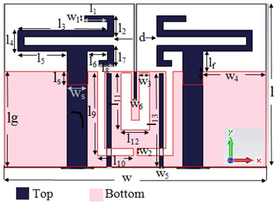
Figure 1: Configuration of the proposed MIMO antenna.
Table 1: Dimensions of the proposed MIMO antenna (in millimeters)
| Parameters | Values | ||
| Length (l) | Width (w) | Length (l) | Width (w) |
| l | w | 3.7 | 0.95 |
| l | w | 3.3 | 1.3 |
| l | w | 14.25 | 1.7 |
| l | w | 3.3 | 9.7 |
| l | w | 7.85 | 0.7 |
| l | w | 3.2 | 0.5 |
| l | w | 3.3 | 3.2 |
| l | w | 2.3 | 41 |
| l | d | 13.2 | 6.8 |
| l | 5.8 | ||
| l | 9 | ||
| l | 4.48 | ||
| l | 14.8 | ||
| l | 2 | ||
| l | 25.5 | ||
| l | 15 | ||
| l | 3.2 | ||
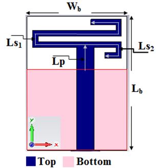
Figure 2: Geometry of the dual-band antenna element.
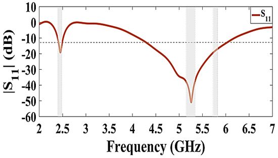
Figure 3: Variation of the antenna reflection coefficient with frequency for the proposed antenna element SEFSA.
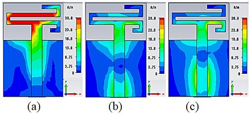
Figure 4: Simulated surface current distributions at; (a) 2.45 GHz, (b) 5.25 GHz, and (c) 5.775 GHz.
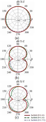
Figure 5: Simulated radiation patterns of the SEFSA at the frequency of 2.45 GHz, 5.25 GHz, and 5.775 GHz for the; (a) XZ plane, (b) YZ plane, and (c) XY plane.
A. Single-element folded strip antenna.
The basic radiating part of the antenna is a monopole formed of two conducting strips for the two desired bands. To achieve a miniaturized design, the radiating strips were folded. Figure 2 shows a single-element folded strip antenna (SEFSA) which is used in the proposed MIMO system. The overall size of the antenna is 24 mm 18 mm. The upper strip of the antenna is used to excite a resonance at the first operating frequency (f = 2.45 GHz) band while the lower strip is used to excite the second resonance frequency (f = 5.25GHz) band. The effective relative permittivity and effective wavelength were calculated using the following relations
| (1) |
| (2) |
where is the relative permittivity of the used substrate. The total average length of the upper strip (Ls + Lp) was set to be /2 and optimized to 37.77 mm /2 (where is the effective wavelength at 2.45 GHz). The total average length of the lower strip (Ls + Lp) was set to be /2 and optimized to 15.63 mm = 0.45 at 5.25 GHz. The feed line position is adjusted carefully to obtain the required dual-band property. The antenna performance was examined and optimized by extensive simulations employing the CST Microwave Studio Software. The Transient Solver was used. The reflection coefficient plot in Figure 3 shows two operating bands within S –10 dB limit. These bands have bandwidths of 120 MHz (2.39–2.51 GHz) and 2.05 GHz (4.13–6.18 GHz), which cover all the 2.4/5.25/5.775 GHz WLAN bands. In the upper frequency band, the resonance frequency is determined by a combination of two factors. The first is the second resonant frequency due to the lower strip while the other frequency corresponds to the higher mode of the upper strip.
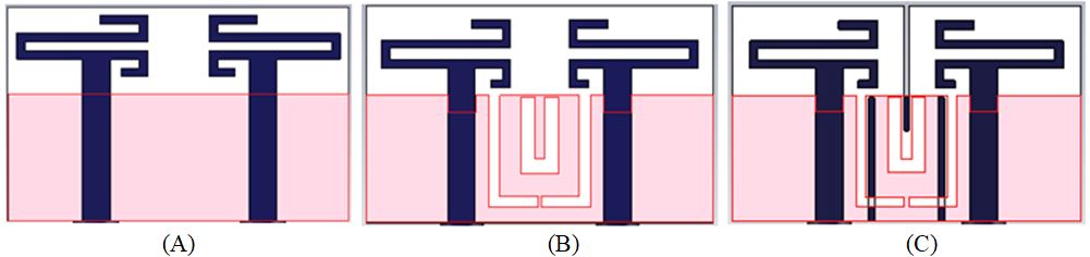
Figure 6: Evolution of the proposed MIMO antenna; (A) Antenna1, (B) Antenna2, and (C) Antenna3.
The surface current distributions in Figure 4 show that the folded strip antenna is resonating at 2.45 GHz and 5.25 GHz frequencies. The upper (long) strip has a higher current density at the lower band (2.45 GHz), while the lower (short) strip carries a high current density at the upper band. The radiation patterns of the SEFSA antenna are displayed in Figure 5 which shows that the radiation pattern in the XZ-plane is omnidirectional and in the YZ-plane is bidirectional. Moreover, the radiation patterns are stable for the three desired frequencies.
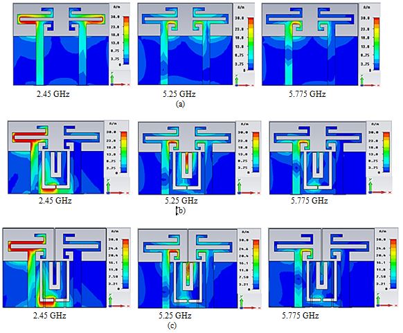
Figure 7: The surface current distributions at 2.45, 5.25, and 5.775 GHz when port 1 is excited and port 2 is terminated to 50 load. (a) Antenna1, (b) Antenna2, and (c) Antenna3.
B. Two-element MIMO antenna
Using the above SEFSA as a reference unit, the two-element MIMO antenna is designed. At first (step 1), two SEFSA antennas are located in adjacent face to face positions with edge to edge distance of 6.8 mm as shown in Figure 6 (a). The overall size of antenna1 in step 1 is 39 mm 24.5 mm.
The surface current distribution in Figure 7 (a) and the S-parameters plot in Figure 8 (a) show that this antenna has a high mutual coupling of –4 dB for the first band and –10 dB for the second band. In order to reduce the mutual coupling at the first band, two L-shaped slots were cut in the ground plane. These L- shaped slots introduce a high impedance region between the feeding lines of the two antennas and enhance the isolation. The length of each slot is set at e/4 at the frequency of 2.45 GHz that is desired to have higher isolation. Thus, the length of the slot L can be calculated using the following relations [25], and found to be 17.9 mm.
| (3) |
| (4) |
To increase the isolation at the frequency of 5.25 GHz a U-shaped slot in the middle of the ground plane was introduced. The U-shaped slot changes the current distribution on the ground plane resulting in higher isolation between the two antennas at 5.25 GHz (Fig. 6 (b)). The length of the U-shaped slot was calculated using eqn (4) and eqn (5), and found to be 16.1 mm. Thus, the MIMO antenna2 is obtained in step 2
| (5) |
The surface current distribution in Figure 7 (b) proves that the mutual coupling due to the surface current propagation and near-field coupling between the antenna elements has been reduced. The S-parameters plot of the proposed MIMO antenna2 in Figure 8 (b) shows that good impedance matching is obtained in the two frequency bands and isolation greater than 19 dB between elements is obtained in the two operating frequency bands. At the 2.45 GHz frequency, the mutual coupling decreased from –4 dB to –24.26 dB, while at the 5.25 GHz band the mutual coupling decreased from –10 dB to –60.37 dB, but at 5.775 GHz it drops from –14.5 dB to –19.9 dB. To obtain a further reduction in the mutual coupling at 2.45 GHz, three slots between the two patches were inserted in the substrate. The length of each slot is equal to 14.8 mm, which is approximately about /4 at 2.45 GHz isolated frequency, thus the proposed MIMO antenna-3 is obtained in step3. Figure 8 (c) displays the simulated S-parameters for double-antenna3. The minimum mutual couplings are –47.8 dB, –61 dB, at 2.47 GHz and 5.2 GHz, respectively. Better isolation has been obtained at the lower band in this case as compared with the previous case. It is 36.86 dB at 2.45 GHz,
which represents a 12.6 dB enhancement over the performance of antenna2.
The simulated radiation pattern of the proposed antenna is shown in Figure 9. Due to the symmetrical structure, the radiation pattern is obtained by exciting one antenna element with the other terminated to a 50 matched load. The results show similar performance at the three bands. Figure 10 shows the simulated efficiency and gain. In the lower band, the minimum efficiency is 81.1% and the minimum gain is 1.84 dBi. In the upper band, the minimum efficiency is 72.3% and the minimum gain is 3.14 dBi.
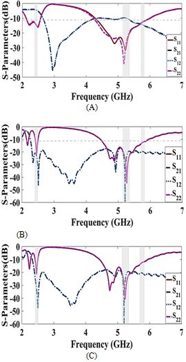
Figure 8: S-parameters of the MIMO antenna; (a) Antenna1, (b) Antenna2, and (c) Antenna3.
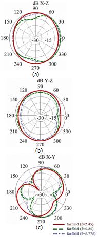
Figure 9: Simulated radiation patterns of the MIMO antenna3 at frequencies of 2.45 GHz, 5.25 GHz, and 5.775 GHz for the; (a) XZ plane, (b) YZ plane, and (c) XY plane.
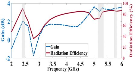
Figure 10: Simulated gain and efficiency of proposed MIMO antenna3.
III. DIVERSITY PERFORMANCE
The performance of the proposed antenna3 was further evaluated by studying the following figure of merits. In each case the antenna performance results were taken from the CST software and applied to codes written in MATLAB to determine, Envelope Correlation Coefficient, Mean Effective Gain, and Total Active Reflection Coefficient, as shown in the next subsections:
A. ECC (Envelope Correlation Coefficient).
For MIMO systems, ECC is an important figure of merit in characterizing the mutual coupling effect between the antenna elements. The value of ECC was calculated from the obtained S-parameters using the following relation:
| (6) |
The ECC must be below 0.5 for good diversity performance [26].
Figure 11 shows the obtained values of ECC. It can be seen that the ECC is less than 0.0043 for the first band (2.4–2.48) GHz, less than 0.00037 for the second band (5.15–5.35) GHz, and less than 0.0023 for the third band (5.725–5.825) GHz. Considerable improvement has been achieved by antenna3 in comparison with antenna1.
B. MEG (Mean Effective Gain).
When contrasted to an isotropic antenna, the mean effective gain (MEG) is the ratio of accepted mean power to average incident power by the radiating element of MIMO. The following equations were used to calculate MEG [27]:
| (7) |
| (8) |
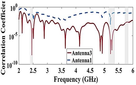
Table 2: Comparison of the performance of the proposed MIMO antenna with some published work
| Ref. | f(GHz) | Edge to edge spacing(mm) | Overall antenna dimensions & volume (mm) | Isolation(dB) | Gain(dBi) | Radiationefficiency [%] | ECC |
| [2] | 5.7 | 4 | 26260.8 = 540 | 15.4 | 1.6 | NA | 0.01 |
| [3] | 8.97 | 1 | 3422 1.5 = 1122 | 43 | 4.5 | 86.96 | 0.018 |
| [5] | 2.44 | 8.4 | 38.295.94 1.6. = 5863 | 24 | 4.68 | 54.99 | 0.008 |
| [9] | 2.45, 5.5 | 17.9 | 50301.59 = 2385 | 24, 27 | 0.26, 3.1 | 32.9, 63.8 | 0.027, 0.005 |
| [12] | 2.45, 5.25 | 9 | 100551.5 = 8250 | 30, 35 | 68, 74 | 0.0003, 0.0001 | |
| [16] | 2.45, 5.5 | 4.8 | 20341.6 =1088 | 21,25 | 2.75–4.19 | 70% | 0.004 |
| [17] | 2.4, 5 | 18 | 607.54.5 = 2025 | 16, 23 | 3.6, 4.15–6 | 7067–78% | NA |
| [18] | 2.42 | 18 | 12060 1.52 = 10944 | 60 | 6.95 | 90 | 0.0093 |
| [19] | 16.05 | 6 | 15301.57 = 7065 | 23.92 | 7.28 | 80.4 | 0.00016 |
| [23] | 2.78, 4.12 | 7 | 75601.6 =7200 | 22, 40 | N.A | N.A | N.A |
| [24] | 2.55 | 15.29 | 5747 9.6 = 25718 | 31 | N.A | N.A | N.A |
| This work | 2.45,5.25 | 6.8 | 25.541 1.5 = 1568.25 | 36.8, 60.37 | 1.9,3.26 | 82.22,79.78 | 1.9 10,8.58 10 |
Figure 11: The calculated envelope correlation coefficient of the proposed MIMO antenna.
MEG1 and MEG2 can be written as,
| (9) |
| (10) |
As can be seen from Figure 12, the MEG is under –3 dB.
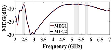
Figure 12: The calculated mean effective gain of antenna3.
C. TARC (Total Active Reflection Coefficient)
The total active reflection coefficient (TARC) denotes the significance of non-variance of the resonance frequency and IBW (Impedance Bandwidth) even when the phase of the input signals, for example, , varies with regard to the other antenna elements [27]. The following formulae can be used to calculate it.
| (11) |
In Figure 13, is consistently changed by 30 steps, but the calculated TARC preserves the reflection coefficient pattern in each case, preserving the resonance characteristic even when the phase of the signal changes.
The comparisons between the proposed antenna and the previously reported MIMO antennas are listed in Table2. Compared with [5,9,12,17,18,23,24] the proposed MIMO antenna has a smaller edge-to-edge distance and size. Compared with [2,5,9,16,17,19,23,24] the proposed MIMO antenna shows higher isolation and efficiency. It is clear that the proposed design provides a low correlation coefficient as compared to those achieved by the other listed works.
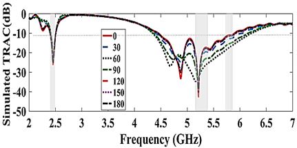
Figure 13: Variation of total active reflection coefficient with a phase angle of antenna3.
IV. CONCLUSIONS
A proposed design of a multi-input multi-output (MIMO) antenna system for wireless devices operating at WLAN (2.45, and 5.25 GHz) bands has been demonstrated in this paper. Each of the two antennas has the shape of two-folded monopoles that cover the 2.45 GHz, and the 5.25–5.775 GHz bands. A new decoupling mechanism in the form of two L-shaped slots and a U-shaped slot is investigated. Three slots on the substrate are inserted between the radiating patches of the MIMO antenna to provide a further reduction in the mutual coupling. The MIMO elements were placed at a small distance of 0.055 (edge to edge). The mutual coupling at the 2.45, 5.2, and 5.775 GHz bands was suppressed to –36.86 dB, –60.3, and –20.61 dB, respectively. The simulated antenna gain is equal to 1.96 dB and the efficiency is 85.85% within the WLAN 2.45 GHz band while the gain is 3.3 dB and the efficiency is 78.16% within the WLAN 5.25 GHz band. The proposed MIMO antenna provides compact size, simple structure, high isolation, and low ECC.
REFERENCES
[1] D.-L. Shen , L. Zhang, Y.-C. Jiao, and Y.-D. Yan, “Dual-element antenna with high isolation operating at the WLAN bands,” Microwave Optical Technology Letters, vol. 61, pp. 2323-2328, 2019.
[2] S. Pandit, A. Mohan, and P. Ray, “A compact four-element MIMO antenna for WLAN applications,” Microwave Optical Technology Letters, vol. 60, pp. 289-295, 2018.
[3] C. Hao, H. Zheng, J. Zhang, and X. Sun., “The deployment of stub structures for mutual coupling reduction in MIMO antenna applications,” Progress In Electromagnetics Research Letters, vol. 92, pp. 39-45, 2020.
[4] W.-H. Chang and S.-W. Su, “Very-low-profile, decoupled, hybrid two-antenna system using top-loaded, coupled strip resonator for notebook computer applications,” Progress In Electromagnetics Research M, vol. 84, pp. 63-72, 2019.
[5] K. Sharma, and G. P. Pandey, “Two-port compact MIMO antenna for ISM band applications,” Progress In Electromagnetics Research C, vol. 100, pp. 173-185, 2020.
[6] T. Agrawal and S. Srivastava, “Compact MIMO antenna for multiband mobile applications,” Journal of Microwaves, Optoelectronics, and Electromagnetic Applications, vol. 16, no. 2, pp. 542-552, Jun. 2017.
[7] K. V. Babu, and B. Anuradha, “Analysis of multi-band circle MIMO antenna design for C-band applications,” Progress In Electromagnetics Research C, vol. 91, pp. 185-196, 2019.
[8] R. Addaci, A. Diallo, C. Luxey, P. L. Thuc, and R. Staraj., “Dual-band WLAN diversity antenna system with high port-to-port isolation,” IEEE Antenna and Wireless Propagation Letters, vol. 11, pp. 244-247, 2012.
[9] W. Wu, R. Zhi, Y. Chen, H. Li, Y. Tan, and G. Liu., “A compact multiband MIMO antenna for IEEE 802.11 a/b/g/n applications,” Progress In Electromagnetics Research Letters, vol. 84, pp. 59-65, 2019.
[10] B. Qian, X. Chen, and A. A. Kishk, “Decoupling of microstrip antennas with defected ground structure using the common/differential mode theory,” IEEE Antennas and Wireless Propagation Letters, vol. 20, no. 5, pp. 828-832, Mar.2021.
[11] A. A. Abdulhammed, A. S. Abdullah, H. M. Al Sabbagh, and H. K. Bashir., “Mutual coupling reduction of a (21) MIMO antenna system using parasitic element structure for WLAN applications,” Journal of Emerging Trends in Computing and Information Sciences, vol. 6, no. 11, pp. 605-613, Nov. 2015.
[12] X. Zou, G. M. Wang, Y. W. Wang and B. F. Zong, “Decoupling of dual-band closely spaced MIMO antennas based on novel coupled resonator structure,” Frequenz, vol. 72, no. 9-10, pp. 437-441,2018.
[13] D.-G. Yang, D. O. Kim, and C.-Y. Kim, “Design of dual-band MIMO monopole antenna with high isolation using slotted CSRR for WLAN,” Microwave and Optical Technology Letters, vol. 56, no. 10, pp. 2252-2257, Oct. 2014.
[14] A. Iqbal, A. Altaf, M. Abdullah, M. Alibakhshikenari, E. Limiti, and S. Kim, “Modified U-shaped resonator as decoupling structure in MIMO antenna,” Electronics, vol. 9, no. 8, pp. 1-13, Aug. 2020.
[15] M. Yang, and J. Zhou, “A compact pattern diversity MIMO antenna with enhanced bandwidth and high-isolation characteristics for WLAN/5G/ WiFi applications,” Microwave Optical Technology Letters, vol. 62, no. 6, pp. 2353-2364, 2020.
[16] R. N. Tiwari, P. Singh, B. K. Kanaujia, S. Kumar and S. K. Gupta “A low profile dual band MIMO antenna for LTE/Bluetooth/Wi-Fi/WLAN applications,” Journal of Electromagnetic Waves and Applications, vol. 34, no. 9, pp. 1239-1253, Jan. 2020.
[17] J.-H. Chou, J.-F. Chang, D.-B. Lin, and T.-L. Wu, ”Dual-band WLAN MIMO antenna with a decoupling element for full-metallic bottom cover tablet computer applications,” Microwave Optical Technology Letters, vol. 60, pp. 1245-1251, 2018.
[18] S. R. Govindarajulu, A. Jenkel, R. Hokayem, and E. A. Alwan, “Mutual coupling suppression in antenna arrays using meandered open stub filtering technique,” IEEE open journal of Antenna and Propagation, vol. 1, pp. 379-386, Jul. 2020.
[19] H. Yon, N. H. Abd Rahman, M. A. Aris, M. H. Jamaluddin, and H. Jumaat, “Parametric Study on Mutual Coupling Reduction for MIMO Future 5G Antennas,” Journal of Electrical and Electronic Systems Research, vol. 16, pp. 59-64, Jun. 2020.
[20] S. P. Biswal, S. K. Sharma, and S. Dasi, “Collocated microstrip slot MIMO antennas for cellular bands along with 5G phased array antenna for user equipment (UEs),” IEEE Access, vol. 8, pp. 209138-209152, 2020.
[21] K. H. Sayidmarie and L. S. Yahya, “Double- monopole crescent-shaped antennas with high isolation for WLAN and WIMAX applications,” Antenna Fundamentals for Legacy Mobile Applications and Beyond, Springer International Publishing, pp. 53-70, 2018.
[22] L. S Yahya, K. H. Sayidmarie, F. Elmegri and R. A. Abd-Alhameed, “ Arc-shaped monopole antennas with reduced coupling for WLAN and WIMAX applications,” IEEE Internet Technologies and Applications (ITA), Wrexham, UK, pp. 218-223, 2017.
[23] Y. Yu, L. Yi, X. Liu, and Z. Gu, ” Mutual coupling reduction of dual-frequency patch antenna arrays,”Applied Computational Electromagnetics Society (ACES) Journal, vol. 31, no. 9, pp. 1092-1099, Sep. 2016.
[24] T. Jiang, T. Jiao, and Y. Li.,“ A Low mutual coupling MIMO antenna using periodic multi-layered electromagnetic band gap structures,” Applied Computational Electromagnetics Society (ACES) Journal, vol. 33, no. 3, pp. 305-311, Mar.2018.
[25] G. Kumer and K. P. Ray, “Broadband Microstrip Antennas,” Artech House, 2003.
[26] H. U. Iddi, M. R. Kamarudin, T. Abdrahman, A. Y. Abdurahman, R. Dewan, and A. S. Azin, “Triple band planar monopole antenna for MIMO application,” Progress In Electromagnetics Research Symposium Proceedings, Sweden, Aug. 12-15, pp. 1421-1424, 2013.
[27] A. Kumar, A. Q. Ansari1, B. K. Anaujia, J. Kishor, and N. Tewari,“ Design of triple-band MIMO antenna with one band-notched Characteristic” Progress In Electromagnetics Research C, vol. 86, pp. 41-53, 2018.
BIOGRAPHIES

Likaa S. Yahya was born in Mosul, Iraq, in 1970. She received a B.Sc. degree in Electrical Engineering from the University of Mosul, Iraq, in 1992, and an M.Sc. degree in Communication Engineering from the University of Mosul, in 2002 and Ph.D. Degree in Communication Engineering from the University of Mosul, in 2017. She is currently a Lecturer at the Dept. of Electronic Techniques, Northern Technical University, Mosul, Iraq. Her interest includes multiband antenna design and antenna modeling.

Loay S. Yahya was born in Mosul, Iraq, in 1963. He received a B.Sc. degree in Electrical Engineering from the University of Mosul, Iraq, in 1985, and an M.Sc. degree in Computer Engineering, University of Mosul, in 2005. He is currently an Assistant-Lecturer at the Dept. of Electronic Techniques, Northern Technical University, Mosul, Iraq. His interest includes Neural Network, Recognition Systems, and antenna design.

Khalil H. Sayidmarie received a B.Sc. degree in Electronics and Communication Engineering from Mosul University, Iraq, in 1976, and Ph.D. Degree in Antennas and Propagation from Sheffield University, U.K. in 1981. Then he joined the College of Engineering at Mosul University in 1983 and was promoted to full professor in 1992. He worked as the head of the electrical engineering department for 9 years. Mr. Sayidmarie served as Prof. of communication engineering at the College of Engineering, University of Amman, Jordan from October 2006 to September 2009, and as the Dean of that college from September 2008 to September 2009. He has been Prof of communication engineering at the college of electronic engineering, Ninevah University since July 2002. He is now Professor Emeritus with the college of electronics engineering, Ninevah University. His research interests cover antennas, propagation, and microwaves, and he has published more than 130 papers in international journals and conferences.
ACES JOURNAL, Vol. 36, No. 12, 1569–1578.
doi: 10.13052/2021.ACES.J.361208
© 2021 River Publishers