Particle Swarm Optimization of Irregular-shaped Hexagon Patch Antenna for 2.4 GHz WLAN Applications
Wei-Chung Weng and Min-Chi Chang
Department of Electrical Engineering
National Chi Nan University, 301, University Rd., Puli, Nantou 54561, Taiwan
wcweng@ncnu.edu.tw, s100323910@mail1.ncnu.edu.tw
Submitted On: August 29, 2021; Accepted On: November 4, 2021
Abstract
This study proposes a patch antenna with an irregular shape on a radiating metal patch for 2.4 GHz WLAN applications. The proposed antenna is optimized using our in-house designed particle swarm optimization (PSO) method. By optimizing the coordinates of each vertex of the hexagon radiating metal patch, the PSO algorithm successfully extends the impedance bandwidth and antenna gain without increasing the size, cost, and complexity of the antenna. The optimized antenna has a unique and irregular shape. Measured impedance bandwidth of 7.71% (2.37–2.56 GHz) and peak gain of 2.84 dBi of the proposed irregular-shaped patch antenna are obtained. The simulated and measured results of reflection coefficient, gain, and far-field radiation are found to be in good agreement with each other, hence evidently confirming the validity of the proposed method. The proposed irregular shaped hexagon patch antenna demonstrates superior performance of impedance bandwidth and antenna gain compared to those of the regular-shaped hexagon patch antenna.
Index Terms: antennas, optimization methods, PSO, and wireless LAN.
I. INTRODUCTION
Patch antennas have been widely applied for wireless communication systems. Patch antennas have advantages of light weight, low profile, and easy fabrication. However, one of the drawbacks of patch antennas is their narrow impedance bandwidth (typically 3–5%). To overcome this drawback, broadening band techniques, such as stacking layers, adding parasitic elements, using slots and short pins, and increasing the thickness of the substrate, can be used. However, these broadening band techniques will complicate the antenna configuration.
The shape of the radiating element on conventional patch antennas is usually regular, such as square, rectangle, circle, triangle, and polygon, on a radiating metal patch. However, irregular shapes and curve shapes can provide more flexibility to achieve wide band specifications. To date, irregular shapes have been less applied to radiators since they are difficult to design.
Transmission-line and cavity models [1] have been commonly used to analyze and design conventional patch antennas. An alternative method is to apply an optimization algorithm in conjunction with a full-wave electromagnetic (EM) simulator to design patch antennas. Using this method, complicated configuration and satisfactory performance of an antenna can be achieved. Many optimization algorithms have been applied to design antennas. In [2] and [3], the numerical electro-magnetics code (NEC) was used as the EM simulator for the genetic algorithm (GA) [4, 5] for the design and optimization of a planar monopole antenna and an electrically small wire antenna. In [6], Taguchi’s method [7] in conjunction with a method of moments (MoM)-based EM simulator, IE3D, was applied to optimize CPW-fed slot antennas. Particle swarm optimization (PSO) method [8] is another popular and effective algorithm to optimize patch antennas [8, 9, 10, 11, 12]. Recently, invasive weed optimization (IWO) algorithm was also applied to optimize a U-slot patch antenna [13] and a meander-shaped MIMO antenna [14].
In this design, we employed our in-house designed PSO method in conjunction with the finite element method (FEM) based EM simulator, HFSS, to design and optimize a regular-shaped hexagon patch antenna. The focus of the proposed approach is to apply the PSO optimizing the coordinates of six vertices of the hexagon radiating patch to extend the impedance bandwidth (BW) and increase gain of the regular-shaped hexagon patch antenna for 2.4 GHz WLAN applications without using any broadening band techniques. In contrast to other optimization works that optimize dimensions of the antenna, the proposed approach, whichoptimizes the coordinates of vertices, provides more flexibility to design the antenna, since the dimensions and shape of the radiating structure are simultaneously changed by the PSO. This approach does not constrain the shape of the antenna during optimization, and the PSO algorithm is free to produce the optimized antenna. The optimized antenna will have the characteristics of low cost, compact size, and simple configuration. Therefore, this design can be considered a challenging task. After optimization, the optimized patch antenna will have a unique and irregular shape on the radiating metal patch. The proposed design method successfully extends the impedance bandwidth and antenna gain. Compared with the regular-shaped hexagon patch antenna, the optimized irregular-shaped patch antenna has wider impedance bandwidth and higher antenna gain. Therefore, the proposed irregular hexagon patch antenna can be considered as a novel patch antenna. The optimization settings of the PSO method and characteristics of the proposed irregular-shaped hexagon patch antenna are presented and discussed. Moreover, this study could serve as a helpful example to design a new patch antenna with satisfactory performance using an optimizationmethod.
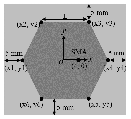
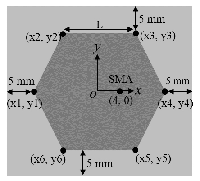
Figure 1: The geometry of initial antenna with a regular hexagon patch.
II. ANTENNA DESIGN AND PSO OPTIMIZATION
Figure 1 shows a regular-shaped hexagon patch antenna, which is denoted as the initial antenna here. The initial antenna is to be fabricated on a cheap FR4 substrate with a thickness of 0.8 mm, a relative dielectric constant of 4.4, and a loss tangent of 0.02. The initial antenna consists of a ground plane printed on the bottom side of the substrate and a metal hexagon patch with six vertices or edges printed on the upper side of the substrate. The center of the antenna structure is located at the origin of the coordinates. The coordinates of the six vertices are located on the x-y plane and measured in millimeters (mm). The initial antenna was designed using the trial-and-error approach. Each edge has a length of L (18 mm) so that the initial antenna can operate in the 2.45 GHz WLAN band with a good impedance matching less than –25 dB. The coordinates of the six vertices for the initial antenna are shown inTable 1.
In our optimization approach, the coordinates of six vertices are to be optimized by using our in-house designed PSO method, which was performed using Matlab version R2016b, to achieve the desired specifications. The main reason of choosing a hexagon-shaped radiating patch instead of a rectangular-shaped radiating patch for the initial antenna is that the hexagon-shaped shape has six vertices, which are two vertices more than the rectangular shape, and can offer more degrees of freedom for optimization. Although a greater number ofvertices for the patch shape, such as octagon or decagon, can be utilized, the solution dimensions will also be increased. And it will cause more complexity of the problem. Hence, it is appropriate to use the hexagon shape patch in this design. The optimization range of each vertex is set to be 0.5 L, which can be considered as the radius of the circle in solution space and hence for searching the optimal antenna shape while the center of the circle is located at each vertex. This arrangement prevents the edges of the patch from overlapping. It is worth noting that the initial values of the vertices are only applied to easily create the geometry of the initial antenna in a full-wave electromagnetic (EM) simulator and to set the optimization range for each vertex. It is not necessary to require the initial antenna to perform well. The PSO method will try to find the optimal solution in the given optimization range, since the PSO method is a global optimizer. The interval between each vertex and the edge of the substrate for clearance is set to be 5 mm as shown in Figure 1. This interval setting can ensure that the location of each vertex will not exceed the edge of thesubstrate. The metal patch is excited by an SMA connector. The location of the SMA connector is fixed at the coordinates (4, 0).
Table 1: Coordinates of six vertices for the initial and optimized hexagon patch antenna
| Coordinates (x, y) | Initial (mm) | Optimized (mm) |
|---|---|---|
| (x1, y1) | (–18.0, 0) | (–22.81, 6.46) |
| (x2, y2) | (–9.0, 15.59) | (–14.03, 10.65) |
| (x3, y3) | (9.0, 15.59) | (1.86, 13.69) |
| (x4, y4) | (18.0, 0) | (13.96, –3.14) |
| (x5, y5) | (9.0, –15.59) | (9.07, –7.74) |
| (x6, y6) | (–9.0, –15.59) | (–12.74, –23.67) |
The desired specifications of the proposed hexagon patch antenna are that the magnitude of reflection coefficient of the antenna () should be less than –10 dB, while the antenna gain () should be at least 3 dBi at frequencies between 2.35 and 2.55 GHz. Therefore, based on the desired specifications, the fitness function for the PSO method is described asfollows:
| (1) | |
where, and are the frequency interval set to be 0.05 GHz and 0.1 GHz, respectively; is –10 dB; gaind is 3 dBi. sgn () equals 1 if the entry is positive, whereas sgn () equals -1 if the entry is negative. The fitness value is a parameter related to the antenna to be designed, such as the reflection coefficient and the antenna gain of the antenna. If is higher than , computing the fitness value is calculated at frequencies between 2.35 GHz and 2.55 GHz. However, computing the fitness value is not performed when is less than –10 dB. The same process is applied to the calculation of the fitness value for the antenna gain. Therefore, a smaller fitness value reflects better antenna performance. In the PSO optimization process, the coordinates of each vertex are varied on the basis of the fitness value in each EM simulation performed by HFSS, and the final solution of the present simulation is then obtained after the iterative operation is completed. In the PSO settings, the maximum number of iterations is set to be 50. The reflecting boundary condition [8] and 36 particles wereused.

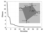
Figure 2: Fitness curve of the PSO optimization for the hexagon patch antenna design. The embedded figure is the geometry of the optimized patch antenna.
This study focuses on the design and optimization of the proposed hexagon patch antenna. Therefore, for a concise reason, other detailed concepts and procedures of the PSO method are not shown here and they can be found in [8] and [10].
III. RESULTS AND DISCUSSIONS
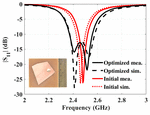
The antenna optimization was performed on a personal computer with a 2.9 GHz Intel i7 870 CPU and 8 GB of memory. Figure 2 shows the fitness curve of the PSO optimization for the hexagon patch antenna design. The PSO process was terminated after 39 iterations since the fitness value was convergent. Theoptimized antenna was then fabricated on the FR4 substrate based on the optimized vertices coordinates presented in Table 1. Figure 2 also reveals the geometry of the optimized hexagon patch antenna, which shows that the shape of its metal radiating patch is irregular. The overall antenna size with 5 mm clearance in each direction of the optimized antenna is 46.7 mm (in the x direction) by 47.4 mm (in the y direction). Measured and radiation patterns were obtained using an Agilent N5230A vector network analyzer (VNA) and an MVG SG-24 antenna measurement system, respectively. Figure 3 exhibits the curves of the optimized antenna and the initial antenna. The embedded photograph shown in Figure 3 is the optimized patch antenna. Good agreements between measured and simulated of the two antennas are observed, which demonstrates the validity of the proposed design. The measured impedance bandwidth (below –10 dB) of the optimized antenna is 0.19 GHz (7.71%, 2.37–2.56 GHz), which is 2.6 times wider than that of the initialantenna.

Figure 3: Reflection coefficients of the initial and optimized antennas. The embedded photograph is the optimized patch antenna fabricated on the FR4 substrate.
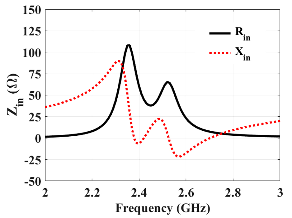
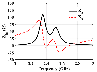
Figure 4: Simulated input impedance of the optimized antenna.
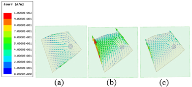
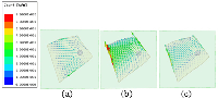
Figure 5: Simulated surface currents of the optimized antenna at (a) 2.38 GHz, (b) 2.45 GHz, and (c) 2.55 GHz.
To better understand the operating principle of the optimized antenna, the input impedance and surface currents of the optimized antenna were simulated. Figure 4 shows the input impedance of the antenna, where . Three resonant frequencies (at = 0) excite at 2.38, 2.42, and 2.52 GHz close to the design frequency at 2.45 GHz, while the real parts () of are near 50 ohms. Hence, the irregular radiating patch excites multi-resonant frequencies around the center frequency of 2.45 GHz resulting in a wide impedance bandwidth.
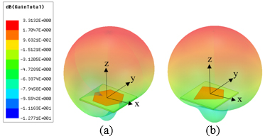
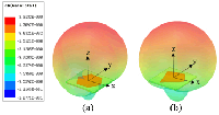
Figure 6: Simulated three-dimensional gain patterns of (a) initial antenna and (b) optimized antenna at 2.45 GHz.
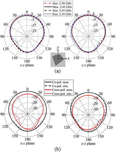
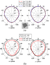
Figure 7: Radiation patterns of the optimized antenna in the x-z and y-z planes, respectively. (a) Gain patterns with different frequencies and (b) normalized co- and cross-polarization radiation patterns at 2.45 GHz.
Figure 5 reveals the simulated surface currents of the optimized antenna at 2.38 GHz, 2.45 GHz, and 2.55 GHz, respectively. There are two modes in the operating band. One mode exists at 2.38 GHz, which is the dominant resonant frequency, and the other one exists around 2.45 GHz to 2.55 GHz. The directions of surface currents in each mode are almost orthogonal to each other.
Figure 6 exhibits the simulated three-dimensional (3D) gain patterns of the initial antenna and the optimized antenna at 2.45 GHz, respectively. Three-dimensional gain patterns of the two antennas are similar to each other. Two antennas have a wide beamwidth and a symmetric pattern in the boresight direction. Figure 7 (a), (b) reveals two-dimensional radiation patterns of the optimized antenna in the x-z and y-z planes, respectively. In addition to 2.45 GHz, two frequency points 2.38 and 2.55 GHz are chosen based on the –10 dB limit of . Again, good agreements between simulated and measured gain patterns at 2.45 GHz are observed, as shown in Figure 7 (a). The measured 3 dB beamwidth is 100 degrees in both the x-z and y-z planes. Meanwhile, the radiation patterns of the optimized antenna do not change much, with the frequencies at 2.38, 2.45, and 2.55 GHz showing stable patterns over the working band.
For the normalized co- and cross-polarization fields of the optimized antenna at 2.45 GHz shown in Figure 7 (b), the level difference between co-polarization and cross-polarization is around 5 dB in the boresight direction. The cross polarization level in the x-z and y-z planes is higher than that of the regular shape initial antenna. The high level of cross-polarization fields is mainly due to the irregular radiating structure of the antenna [15, 16]. Meanwhile, the polarization conditions are not included in the fitness function shown in (1) when optimizing the proposed antenna. Ideally, the level difference of the two orthogonal fields should bemaximal for linear polarization. However, these high cross-polarization fields could be an advantage in WLAN communications [16] and a potential property for designing a circularly polarized antenna.
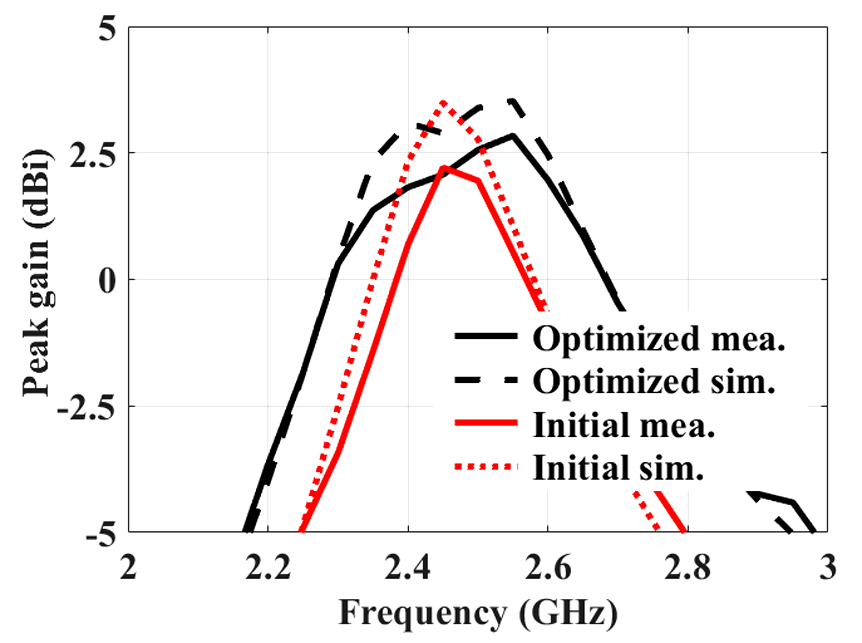
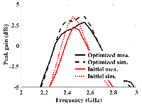
Figure 8: Measured and simulated peak gains of the initial and optimized antennas.
Table 2: Measured results comparison between initial and optimized hexagon patch antennas
| Antenna | Bandwidth (GHz) |
Peak gain (dBi) |
Size (mm) |
|---|---|---|---|
| Initial | 3.02 %,2.44-2.52 | 2.21 | 46.0 41.2 |
| Optimized | 7.71 %,2.37-2.56 | 2.84 | 46.7 47.4 |
The measured peak gains of the optimized antenna are 2.07 dBi at 2.45 GHz and 2.84 dBi at 2.55 GHz, which are usually higher than those of the initial antenna, as shown in Figure 8. Additionally, the bandwidth of peak gain of the optimized antenna is also wider than that of the initial antenna, while the optimized antenna almost maintains the same antenna size. Comparisons of measured results, such as impedance bandwidth, peak gain, and overall size of the two antennas at 2.45 GHz, are tabulated in Table 2. Apparently, the performance of the optimized irregular-shaped hexagon patch antenna outperforms the initial antenna in impedance bandwidth and antenna gain. The proposed optimization approach successfully achieves the desired specifications of the proposed antenna. The optimized irregular-shaped hexagon antenna is suitable for 2.4 GHz WLAN applications.
IV. CONCLUSION
This paper presents a novel irregular-shaped hexagon patch antenna for 2.4 GHz WLAN applications. The in-house designed PSO code has been combined with the electromagnetic simulator, HFSS, to design and optimize the proposed antenna. By optimizing the coordinates of the vertices, the proposed irregular-shaped hexagon patch antenna has been designed via the PSO method on the unconstrained shape of the antenna. Optimization settings for the PSO method have been provided. The proposed approach successfully extends the impedance bandwidth and antenna gain without using any other broadening band techniques, such as stacking layers, adding parasitic elements, using slots and shorting pins, and increasing the thickness of the substrate. Therefore, the proposed approach has achieved the characteristics of compact size, low profile, simple structure, and low cost of the proposed antenna. The proposed irregular hexagon patch antenna has exhibited superior performance in impedance bandwidth and antenna gain compared to those of the regular hexagon patch antenna. Meanwhile, the fabrication process of the proposed irregular-shaped patch antenna is the same as that of regular-shaped patch antennas. Hence, there are no extra costs or challenges in the antenna fabrication process. This study also shows that the irregular shapes adopted for antenna designs can provide better antenna performance in the case of the proposed antenna. The proposed irregular-shaped hexagon patch antenna can be a promising candidate for applications in 2.4 GHz WLAN systems.
ACKNOWLEDGMENT
The authors thank the National Center for High-performance Computing for providing software and facilities. This work was supported in part by the MOST under Grant 110-2221-E-260-007.
REFERENCES
[1] C. A. Balanis, Antenna Theory Analysis and Design, 3rd ed., John Wiley & Sons Inc., pp. 816-839, 2005
[2] A. J. Kerkhoff, R. L. Rogers, and H. Ling, “Design and analysis of planar monopole antennas using a genetic algorithm approach,” IEEE Trans. Antennas Propag., vol. 52, no. 10, pp. 2709-2718, Oct. 2004.
[3] H. Choo, R. L. Rogers, and H. Ling, “Design of electrically small wire antennas using a pareto genetic algorithm,” IEEE Trans. Antennas Propag., vol. 53, no. 3, pp. 1038-1046, Mar. 2005.
[4] R. L. Haupt, “An introduction to genetic algorithms for electromagnetics,” IEEE Antennas Propag. Mag., vol. 37, pp. 7-15, Apr. 1995.
[5] Y. Rahmat-Samii and E. Michielssen, Electromagnetic Optimization by Genetic Algorithms. New York: Wiley, 1999.
[6] W. C. Weng and C. T. M. Choi, “Optimal design of CPW slot antennas using Taguchi’s method,” IEEE Trans. Magn., vol. 45, no. 3, pp. 1542-1545, Mar. 2009.
[7] W. C. Weng, F. Yang, and A. Z. Elsherbeni, Electromagnetics and Antenna Optimization Using Taguchi’s Method, Morgan and Claypool Publishers, pp. 1-84, 2007.
[8] J. Robinson and Y. Rahmat-Samii, “Particle swarm optimization in electromagnetics,” IEEE Trans. Antennas Propag., vol. 52, no. 2, pp. 397-407, Feb. 2004.
[9] M. C. Tang, X. Chen, M. Li, and R. W. Ziolkowski, “Particle swarm optimized, 3-D-printed, wideband, compact hemispherical antenna,” IEEE Antennas Wireless Propag. Lett., vol. 17, pp. 2031-3035, 2018.
[10] W. C. Weng, “Optimal design of an ultra-wideband antenna with the irregular shape on radiator using particle swarm optimization,” Applied Computational Electromagnetic Society (ACES) Journal, vol. 27, no 5, pp. 427-434, May 2012.
[11] W. C. Weng and C. L. Hung, “An H-fractal antenna for multiband applications,” IEEE Antennas Wireless Propag. Lett., vol. 13, pp. 1705-1708, 2014.
[12] L. Lizzi and A. Massa, “Dual-band printed fractal monopole antenna for LTE applications,” IEEE Antennas Wireless Propag. Lett., vol. 10, pp. 760-763, 2011.
[13] S. Karimkashi and A. A. Kishk, “Invasive weed optimization and its features in electromagnetics,” IEEE Trans. Antennas Propag., vol. 58, no. 4, pp. 1269-1278, Apr. 2010.
[14] B. Bahreini, A. Mallahzadeh, and M. Soleimani, “Design of a meander-shaped MIMO antenna using IWO algorithm for wireless applications,” Applied Computational Electromagnetic Society (ACES) Journal, vol. 25, no 7, pp. 631-638, Jul. 2010.
[15] A. A. Minasian and T. S. Bird, “Particle swarm optimization of microstrip antennas for wireless communication systems,” IEEE Trans. Antennas Propag., vol. 61, no. 12, pp. 6214-6217, Dec.2013.
[16] K. Bahadori and Y. Rahmat-Samii, “A miniaturized elliptic-card UWB antenna with WLAN band rejection for wireless communications,” IEEE Trans. Antennas Propag., vol. 55, no. 11, pp. 3326-3332, Nov. 2007.
BIOGRAPHIES

Wei-Chung Weng received the B.S. degree in electronic engineering from National Changhua University of Education, Changhua, Taiwan, in 1993, the M.S. degree in electrical engineering from I-Shou University, Kaohsiung, Taiwan, in 2001, and the Ph.D. degree in electrical engineering from The University of Mississippi, MS, USA, in 2007.
In 2008, he joined the Department of Electrical Engineering, National Chi Nan University, Puli, Taiwan, where he is currently an Associate Professor. From 2017 to 2018, he was a Visiting Scholar at the Department of Electrical Engineering, Colorado School of Mines, Golden, CO, USA. From 2004 to 2007, he was a Graduate Research Assistant in the Department of Electrical Engineering, The University of Mississippi. He has authored or coauthored more than 50 journal articles and conference papers and a book entitled Electromagnetics and Antenna Optimization Using Taguchi Method (Morgan & Claypool, 2007). His research interests include antenna and microwave circuit design, computational electromagnetics, electromagnetic compatibility, and optimization techniques in electromagnetics.
Dr. Weng is the Associate Editor-in-Chief for Applied Computational Electromagnetics Society (ACES) Journal. He has served many journals as a reviewer for years. He is a Member of ACES, a Senior Member of IEEE, and a Life Member of the Institute of Antenna Engineers of Taiwan (IAET). He was the recipient of the Outstanding Teaching Award of National Chi Nan University in 2013, 2016, and 2019 and the Teaching Contribution Award of the same university in 2020.

Min-Chi Chang Min-Chi Chang was born in Yunlin, Taiwan. He received the B.S. degree in electrical engineering from National United University, Miaoli, Taiwan, in 2009. He is currently working toward the Ph.D. degree in the Department of Electrical Engineering, National Chi Nan University, Puli, Taiwan. His research interests focus on antenna design, computational electromagnetics, and optimization techniques in electromagnetics.
ACES JOURNAL, Vol. 36, No. 12, 1535–1540.
doi: 10.13052/2021.ACES.J.361204
© 2021 River Publishers