Compact Dual-Band Bandpass Filter Based on SSL-SIR With Sharp Roll-Off
Juan Yue, Guanmao Zhang, Zonge Che, Yupeng Lun, Zhihang Li, and Junhong Suo
Institute of Optoelectronics and Electromagnetics Information, School of Information Science and Engineering,
Lanzhou University, Lanzhou 730000, P. R. China
zhanggm@lzu.edu.cn
Submitted On: August 29, 2021; Accepted On: December 28, 2021
Abstract
A compact dual-band bandpass filter (DB-BPF) is studied and implemented by using shorted stub-loaded stepped impedance resonator (SSL-SIR) and 0feed structure in this paper. The resonance frequencies of SSL-SIR can be analyzed and explained by oddeven mode analysis method and it is used in the design of BPF I. Then, the BPF II is created using the theory of 0feed structure. Finally, the two structures are combined together to form a DB-BPF by reasonably adjusting the coupling between them and the position of the feed points. The simulation results suggest that the center frequencies of the two passbands are 3.45 and 5.2 GHz, respectively, which are suitable for modern wireless communication systems like 5G and WLAN. Compact size, strong passband isolation, and large stopband bandwidth are all advantages of the proposed DB-BPF filter. A prototype is created and constructed to validate this. The simulated results are in good agreement with the measured results.
Index Terms: Dual-band bandpass filter (DB-BPF), 0feed structure, stub-loaded stepped impedance resonator (SSL-SIR).
I. INTRODUCTION
As we all know, filters play an essential role in many radio frequency (RF) or microwave systems with the development of modern technology. The filters are widely utilized in many sectors such as WiFi, sensing radars, and transceivers due to their great qualities such as compact size, low cost, low insertion loss, superior frequency selectivity, and ease of production. Recently, with the continuous progress of multi-function wireless communication networks, the single band transceiver system has been unable to meet the requirement. Therefore, the diversified function and excellent performance of wireless devices become the focus of attention. To meet various demands, filters that possess multiple functions have been developed by researchers, such as lowpass filters with good out-of-band suppression [1],band-stop filters [2], tunable filters [3], reconfigurable filters [4], and bandpass filters (BPFs) [5].
Dual-band bandpass filters (DB-BPFs) have a lot of promise due to the growing demand for RF transceivers that operate in several frequency bands. Many methods have been developed, and a variety of DB-BPF structures have been proposed using various techniques, such as the DB-BPF based on the hexagonal split ring resonator [6], the dual wide-band BPF based on the cross-shaped resonator [7], the compact DB-BPF based on shorted and open stub-loaded resonators [8, 9], and the DB-BPF based on dual-mode resonators [10].
The DB-BPFs based on the shorted stub-loaded stepped impedance resonator (SSL-SIR) have also been presented in [11, 12, 13, 14], in addition to the filters mentioned above. SIRs have the advantages of a simple design, easy manufacture, and a high stopband attenuation level. The DB-BPF in [11] was combined by a pair of open stub-loaded stepped impedance resonators (OSLSIRs) and two SSL-SIRs are embedded between the coupled OSLSIRs to generate quasi-elliptic response at two diverse frequencies, but its whole frame was suffered from great size and complicated structure. In [12], a pair of stub-loaded SIRs and a pair of dual-feedline structures (DFSs) were used to design DB-BPF. However, it was lack of passband selectivity and compactness. A novel compact DB-BPF based on SSL-SIR and a pair of tri-section stepped impedance resonator (T-SIR) was presented in [13], whereas its circuit was not compact enough and simple. In [14], the DB-BPF was constructed by a quad-mode stub-loaded resonator, yet, it occupied a large area.
As previously stated, the DB-BPF built by others required a considerable dimension due to the large number of resonators required. A miniaturized DB-BPF based on SSL-SIR and 0feed structure is proposed in this paper. First, the theory of oddeven mode analysis is used to analyze SSL-SIR, and then the low passbandcentered at 3.45 GHz is designed. Based on the theory of 0feed structure, the upper passband centered at 5.2 GHz is formed. The two passbands are combined together to form a DB-BPF by reasonably adjusting the coupling between them and the position of the feed points. Finally, a prototype is fabricated and measured, and the measured results verify the rationality of the design.
II. DESIGN OF BPF I
A DB-BPF which composed of SSL-SIR and a two-mode resonator based on a 0feed structure. Its topology was depicted in Figure 1. The typical SSLR, as shown in Figure 2, is made up of a uniform microstrip line and a shorted stub-loaded resonator in the center, with physical lengths defined as 2L and L. Its impedances are Z and Z, respectively. By replacing the short one to the open one, the diagram is named OSLR. Due to the symmetrical structures of SSLR and OSLR, the resonant characteristics can be easily analyzed by the oddeven mode analysis method.
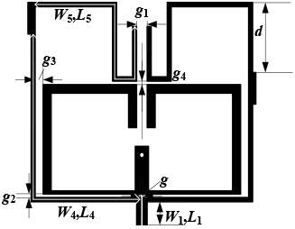
Figure 1: Geometry of the proposed DB-BPF.
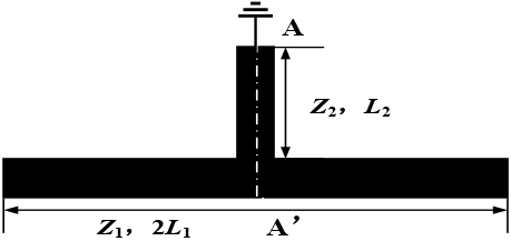
Figure 2: Diagram of a typical SSLR.
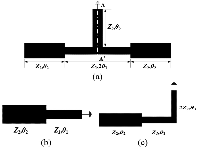
Figure 3: (a) Structures of SSL-SIR. (b) Odd-mode equivalent circuit of SSL-SIR. (c) Even-mode equivalent circuit of SSL-SIR.
Here, the SSL-SIR is used to form BPF I and its topology and the oddeven mode equivalent circuit are shown in Figure 3. The two characteristic impedances and electrical lengths of SIR are Z, Z, 2 , and . The impedance of the loaded short circuit uniform impedance stub microstrip line is Z, and the electric length of corresponding microstrip line is . Since SSL-SIR is symmetric about A, A’, the resonant frequency of this structure can also be analyzed by using the oddeven mode analysis method. According to the transmission line theory, the input impedance of odd mode can be given by:
| (1) |
Based on the resonance condition 1/Z= 0, it can be deduced that when the resonator resonates, its electric length should meet condition (2). Further, define the electric length ratio , = + , = /, and formula (2) can be converted into formula (3). The odd-mode equivalent circuit structure is also known as a quarter wavelength SIR.
| (2) |
| (3) |
It can be seen from formula (3), which determines the odd mode resonance frequency (f), that when the structural parameters of the loaded shorted uniform impedance stub of microstrip line are changed, the odd-mode resonant frequency will not change at all. It is mainly determined by the impedance ratio Z/Z of SIR and the electric lengths and .
Similarly, the input impedance of even mode can be given by:
| (4) | |
According to the resonance condition 1/Z= 0, it can be computed that when the resonator resonates, its electric length should meet the followingcondition:
| (5) | |
Further obtained:
| (6) | |
where R= Z/Z and R= Z/Z; hence, Z/Z= RR. From (6), we can see that the even mode resonance condition of SSL-SIR is not only related to the impedance ratio R and the electrical length and of SIR but also related to the impedance ratio R and the electrical length of the loaded shorted stub. We first calculated the electrical parameters based on the f and f determined by formula (3) and formula (6) and then optimized the final electrical parameters in the simulation software. In this study, the impedance ratio of the SSL-SIR R and Rare set as 0.8 and 1.6, respectively, and the electric lengths , , and are obtained as 27, 57, and 11independently at 3.45 GHz.
In comparison to a traditional SSLR, the design of a filter employing SSL-SIR will have more flexibility and degrees of freedom, which will considerably improve the adjustable range of filter performance in actual applications.
A small size BPF with a center frequency of 3.45 GHz was designed by reasonably selecting the electrical length, impedance ratio of SSL-SIR and utilizing the coupling of source/load. SSL-SIR bending is designed to reduce the size of the circuit. Simultaneously, the geometry of the proposed filter and its simulation results are shown in Figure 4. The feed lines on the left and right ends are 50 . It can be seen that there are two transmission zeros on the left and right sides of the passband. The transmission zeros are introduced through the source load coupling, which can significantly improve the selectivity and out-of-band rejection response of the filter.
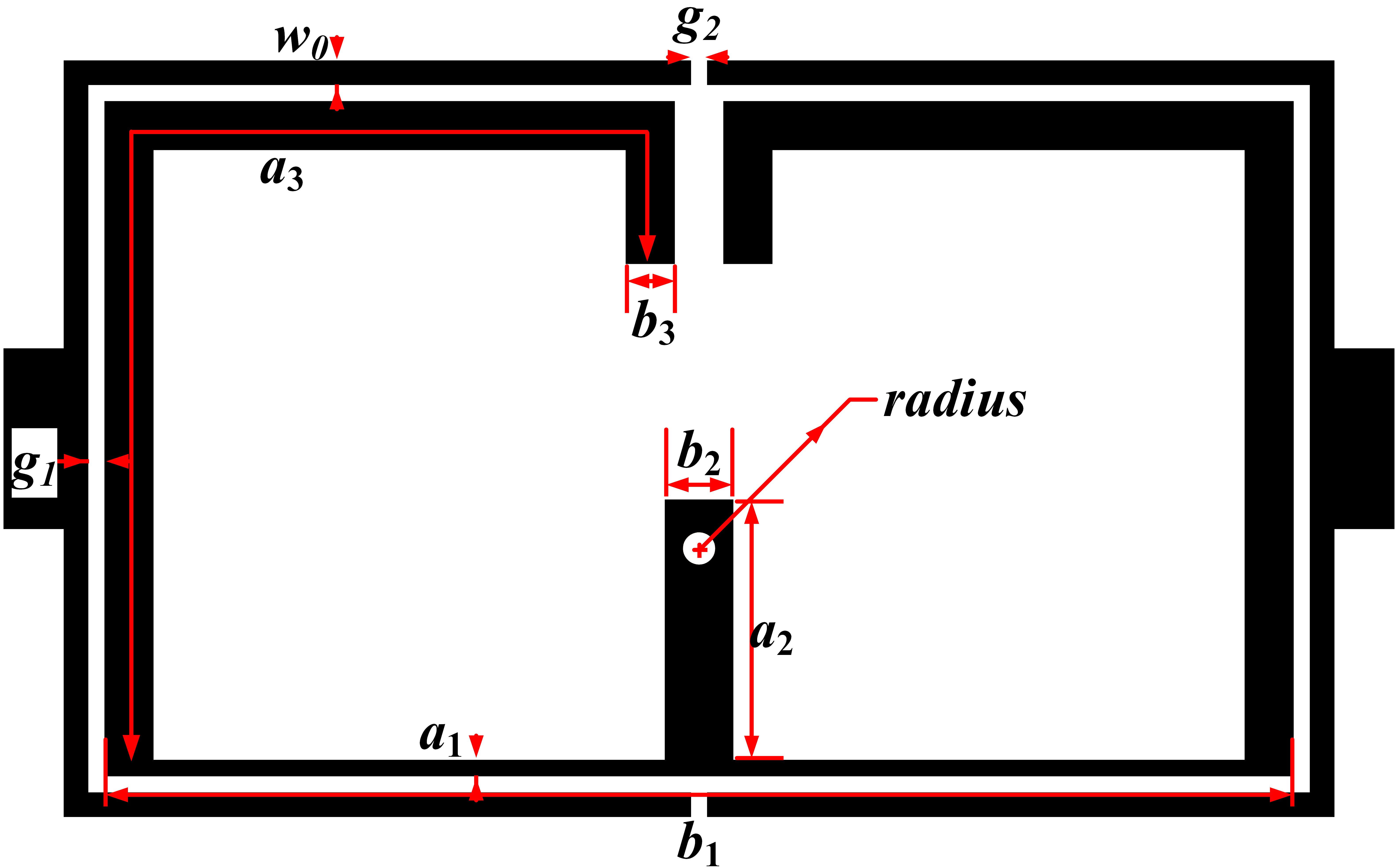
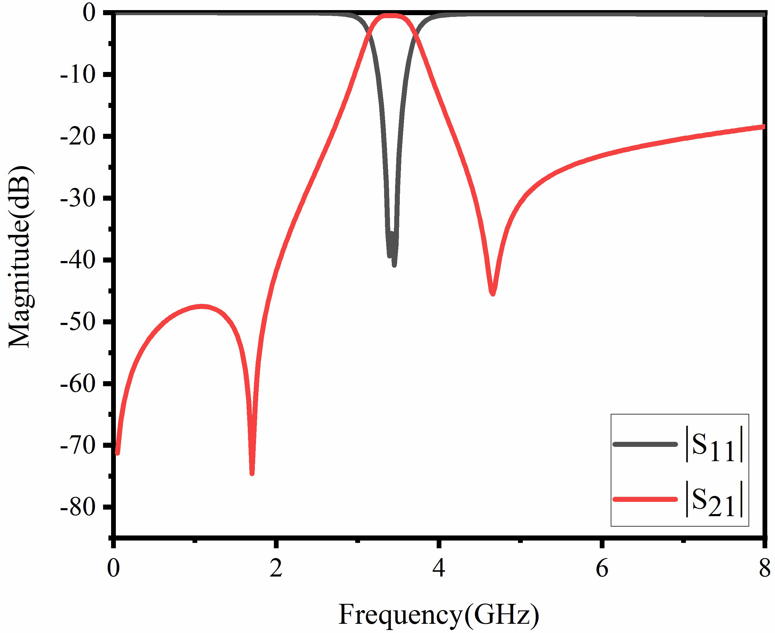
Figure 4: Geometry of the proposed BPF I and its simulation results. (a) Geometry of the filter (a= 0.11, b= 7.4, a= 1.55, b= 0.5, a= 7.91, b= 0.3, radius = 0.1, W= 0.15, g= 0.1, and g= 0.1 all in millimeter). (b) Simulated S parameters of the passband I.
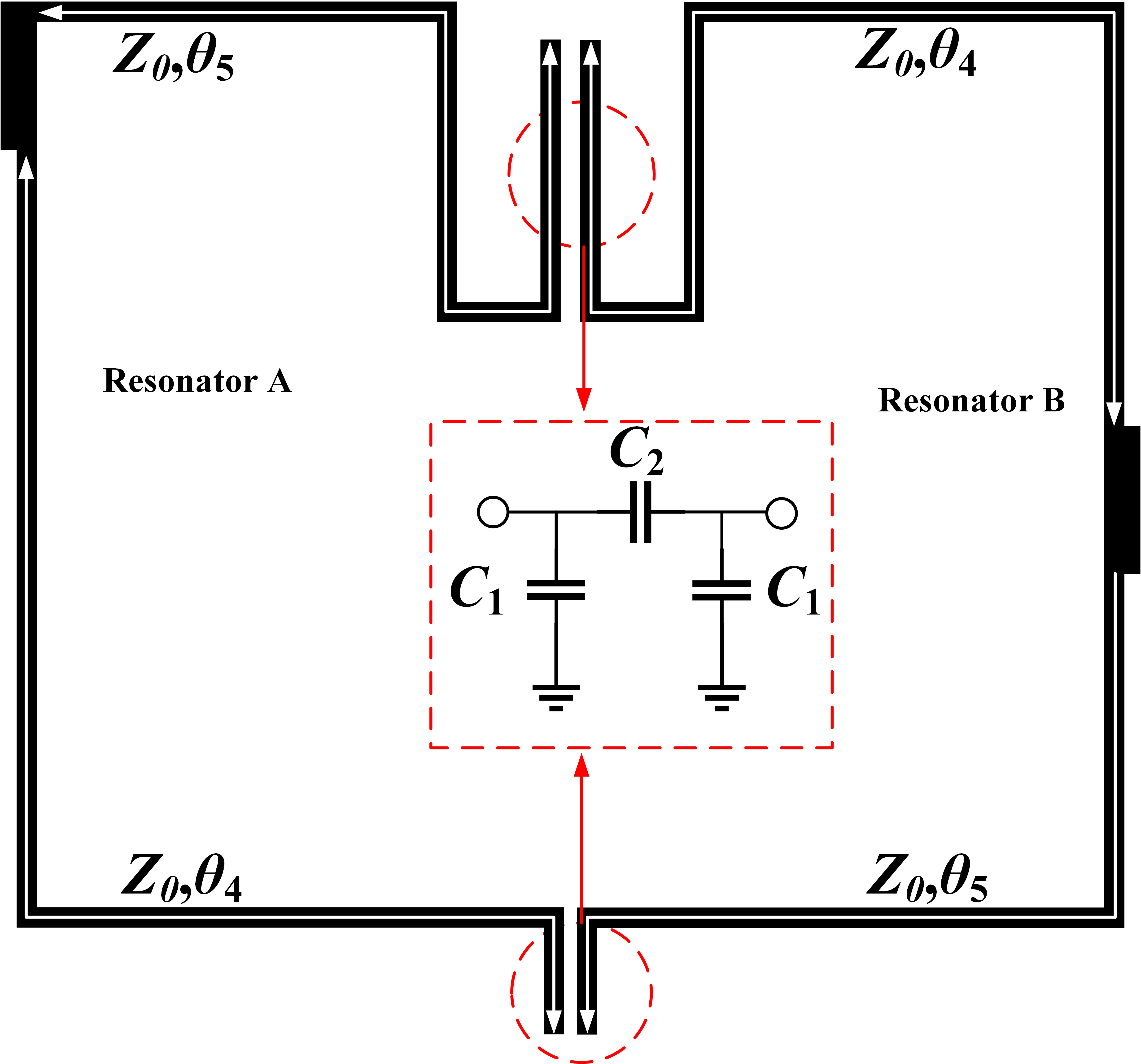
Figure 5: The topology structure of BPF II.
III. DESIGN OF BPF II
As shown in Figure 5, the design of BPF II was inspired by [15] based on the theory of 0feed structure and electric coupling. According to the previous research results, the frequency responses of the filters designed with different tap-line feed points may be significantly different. It has been found in [16] that by using a 0feed structure, two transmission zeros near the passband can be generated and the stopband rejection has been significantly increased. The electrical delays of the upper and lower paths of the coupling structure in Figure 5 are similar to those at its fundamental resonant frequency which has a 0 difference between the electric delays of the lower and upper paths. Also, the coupling gaps between the two resonators are modeled as -networks, as shown in the inset of Figure 5, where the values of C and C could be found from [17]. For a lower microwave frequency range, the value of C is very small due to C 0.01 pF, and it will be neglected.
The transmission matrix of BPF II can be derived from [18], and its transmission coefficient can be further obtained. Figure 6 is the comparison of the BPF2 without 0 feed structure and with 0 feed structure at the center frequency 5.2 GHz. One resonator is resonant at the frequency when approaches /2 and the other is resonant at the frequency when is approximately /2.
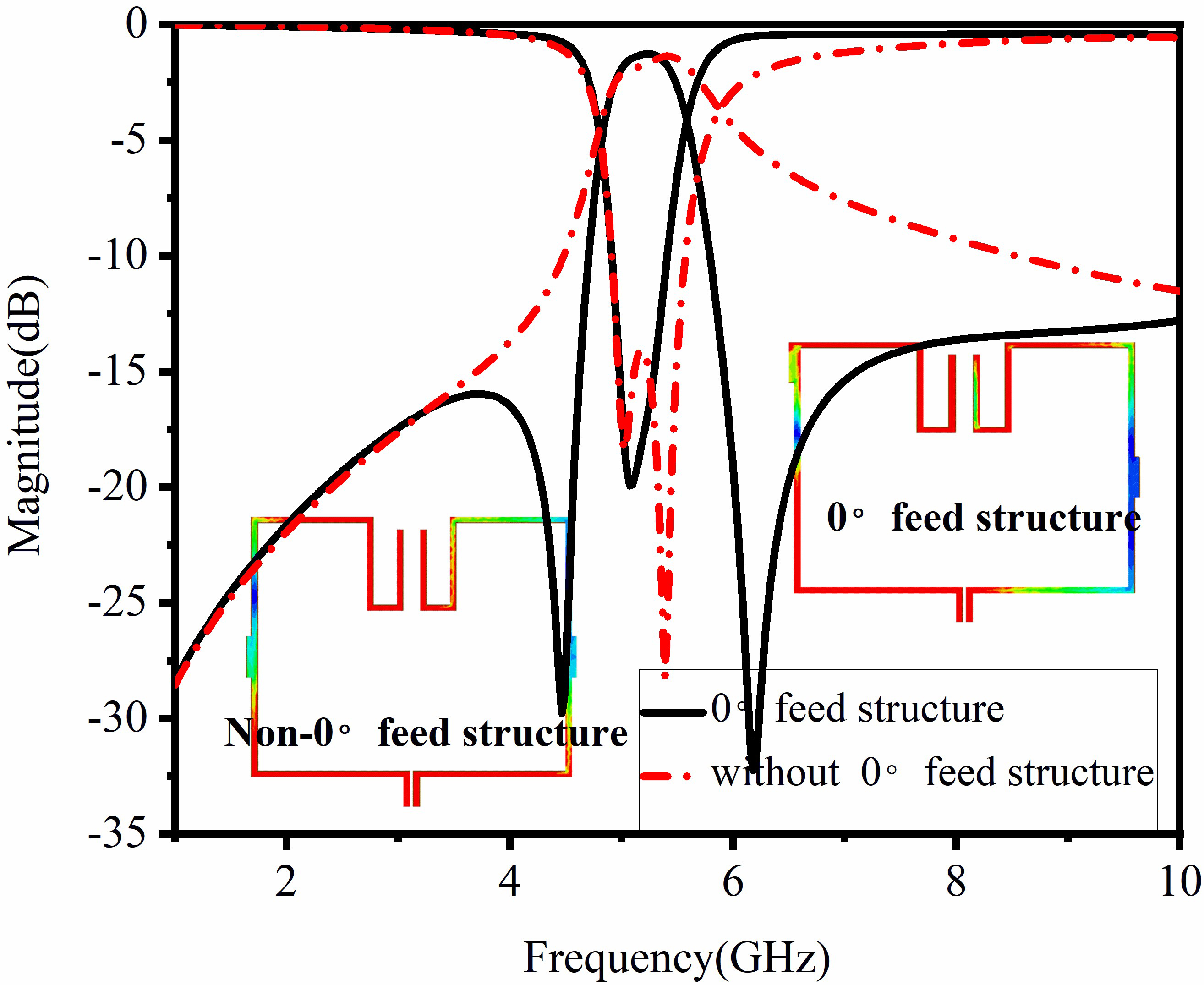
Figure 6: Simulated results of BPF II with 0feed structure and without 0feed structure. (The insets are simulated electric field distribution in 5.2 GHz.)
It can be clearly seen that two transmission zeros which are located at 4.47 and 6.18 GHz, respectively, which are close to the passband and on both sides of the passband; therefore, significant increase has occurred in the stopband injection.
IV. DB-BPF AND EXPERIMENTAL VERIFICATION
A DB-BPF, as shown in Figure 1, is proposed based on the study of the previous two BPFs. The coupling gap between the two filters and the electrical coupling gap of the second filter are tuned by combining the two previously stated BPF I (3.45 GHz) and BPF II (5.2 GHz) together, and the DB-BPF is simply created. The simulated transmission coefficients of the sub-BPF1, sub-BPF2, and DB-BPF are shown in Figure 7. The proposed DB-BPF’s two passbands are clearly in good accordance with the passbands of the two sub-filters. At the same time, the selectivity between the two passbands and the isolation between the two passbands are significantly improved. The final optimized dimensions of the DB-BPF demonstrated in Figure 1 are as follows: g = 0.1 mm, g= 0.4 mm, g= 0.12 mm, g= 0.3 mm, d = 2.44 mm, W= 0.15 mm, L= 0.8 mm, W= 0.15 mm, L= 8.14 mm, W= 0.15 mm, and L= 9.78 mm, where the dimensions of BPF I are the same as Figure 4.
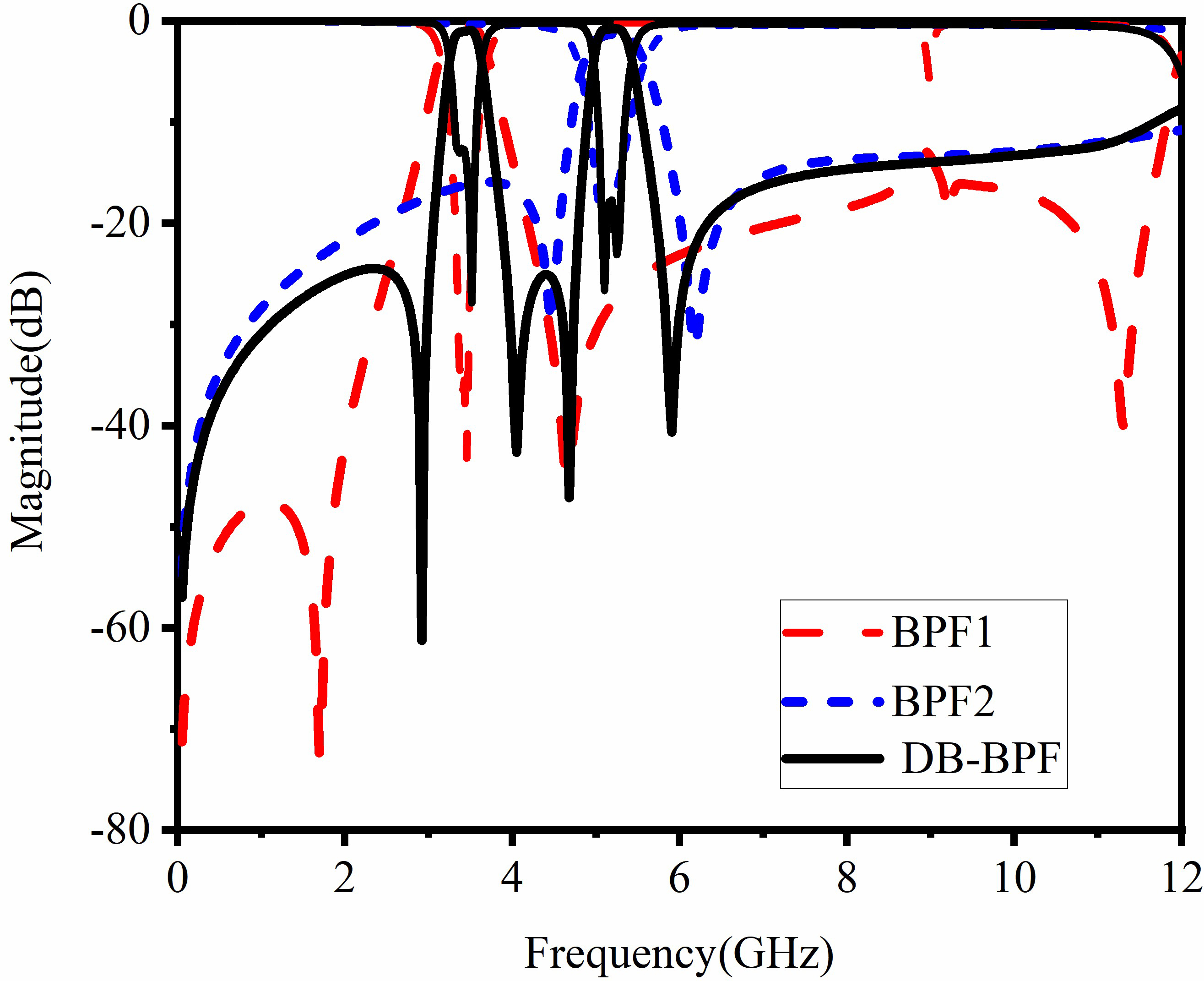
Figure 7: EM simulated results of transmission coefficients of the proposed DB-BPF and sub-filters.
For verification, a DB-BPF is fabricated and measured. Considering the advantages of dimensional stability, low loss, low water absorption, low cost of printed circuit manufacturing, and easy drilling and plating operations. We used Taconic RF-35 substrate with a relative dielectric permittivity of 3.5 and a thickness of 0.508 mm. Figure 8(a) shows the photograph of the fabricated DB-BPF and the comparison between the simulated and measured results. Good agreements are obtained between them, while the slight deviation of the upper passband may be due to the fabrication tolerance and soldering errors at the two 50 input–outputports.
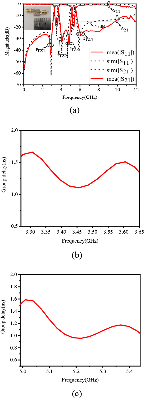
Figure 8: Responses and group delays of the proposed filter. (a) Simulated and measured S-parameters of the DB-BPF. (b) and (c) Simulated in-band group delay responses of passbands I and II, respectively.
The two measured passbands are centered at 3.46 and 5.34 GHz with the fractional bandwidths of 6.9% and 4.4%. The measured minimum insertion losses in the passband are 1 and 1.21 dB. Meanwhile, the return losses are better than 11 and 15 dB, respectively. Four transmission zeros that are located at 2.86, 4.05, 4.8, and 6.05 GHz improve the selectivity of each passband and the isolation between the two passbands. Figures 8(b) and (c) show the simulated in-band group delay responses of low passband and high passband, and the minimum group delays in the two passbands are 1.1 and 0.96 ns, respectively. In addition, it has a wide upper stopband ranging from 5.73 to 9.86 GHz with 15 dB injection. The overall size of the filter is 7.74 mm 8.54 mm, which occupies 0.15 0.16 , where is the guided wavelength at the center frequency of the first passband. A performance comparison between the published DB-BPFs and the proposed one is shown in Table 1. It shows that the proposed DB-BPF has the advantages of compact size, low insertion loss, simple circuit topology, and easy fabrication. Comparing with [13], the structure required to design the low passband is simpler and easier to design.
Table 1: Comparison of some previous dual-band filters
| CF(GHz) | FBW (%) | IL (dB) | TZs | Size(*) | |
| [11] | 1.63/2.73 | 7.5/5.1 | 1.5/2.15 | 7 | 0.25*0.25 |
| [12] | 2.3/3.5 | 2.98/2.64 | 1.25/1.72 | 3 | 0.25*0.23 |
| [13] | 2.4/3.5 | 15.6/5.2 | 1.07/1.05 | 4 | 0.32*0.11 |
| [14] | 2.4/5.2 | 14.8/12.9 | 1.43/1.34 | 4 | N.A. |
| This work | 3.46/ 5.34 | 6.9/4.4 | 1/1.21 | 4 | 0.15*0.16 |
V. CONCLUSION
A compact DB-BPF which is composed of BPF I and BPF II, based on the SSL-SIR and 0feed structure, is presented in this article. SSL-SIR is first analyzed using the oddeven mode analysis approach, and then the low passband, centered at 3.46 GHz, is built on this premise. A high-selectivity high passband centered at 5.37 GHz is presented based on the 0feed structure. Without increasing the size of the circuit, a small DB-BPF with good selectivity is created by combining two independent passbands. After all, a DB-BPF is designed, manufactured, and tested. The measured results are in good agreement with the simulation results. The proposed DB-BPF has the merits of compact size, high selectivity, and independent control of the passband, making it suitable for 5G, WLAN, and narrowband applications.
ACKNOWLEDGMENT
This work is supported by the project of the State Key Program of National Natural Science of China under Grant 61631007, the National Key R&D Program of China under Grant 2019YFA0405403, and the Key Project of Innovation and Entrepreneurship of Lanzhou University under Grant cxcy202002.
REFERENCES
[1] M. A. Pahlavani, M. Moradkhani, and R. Sayadi, “New design of an adjustable compact microstrip lowpass filter using Z-shaped resonators with low VSWR,” Microwave and Optical Technology Letters, vol. 62, no. 11, pp. 3527-3535, Jun. 2020.
[2] Q. Li, X. Chen, P. L. Chi, and T. Yang, “Tunable bandstop filter using distributed coupling microstrip resonators with capacitive terminal,” IEEE Microwave and Wireless Components Letters, vol. 30, no. 1, pp. 35-38, Jan. 2019.
[3] L. Gao, T. W. Lin, and G. M. Rebeiz. “Design of tunable multi-pole multi-zero bandpass filters and diplexer with high selectivity and isolation,” IEEE Transactions on Circuits and Systems I: Regular Papers, vol. 66, no. 99, pp. 3831-3842, Oct. 2019.
[4] A. Bandyopadhyay, P. Sarkar, T. Mondal, and R. Ghatak, “A Dual Function Reconfigurable Bandpass Filter for Wideband and Tri-band Operations,” IEEE Transactions on Circuits and Systems II: Express Briefs, vol. 68, no. 6, pp. 1892-1896, Jan. 2021.
[5] J. Hu, Y. Li, D. Zeng, W. Xu, and G. Lu “Design of a broadband microstrip bandpass filter,” 2020 IEEE International Symposium on Antennas and Propagation and North American Radio Science Meeting, pp. 315-316, Jul. 2020.
[6] Z. Troudi, Jan Machá, and L. Osman, “Compact dual-band bandpass filter using a modified hexagonal split ring resonator,” Microwave and Optical Technology Letters, vol. 62, no. 5, pp. 1893-1899, Jan. 2020.
[7] X. K. Bi, X. Zhang, S. W. Wong, T. Yuan, and S. H. Guo, “Design of equal-ripple dual-wideband bandpass filter with minimum design parameters based on cross-shaped resonator,” IEEE Transactions on Circuits and Systems II: Express Briefs, vol. 67, no. 10, pp. 1780-1784, Oct. 2019.
[8] F. Wei, J. H. Yu, C. Y. Zhang, C. Zeng, and X. W. Shi, “Compact balanced DB-BPFs based on short and open stub loaded resonators with wide common-mode suppression,” IEEE Transactions on Circuits and Systems II: Express Briefs, vol. 67, no. 12, pp. 3043-3047, Dec. 2020.
[9] C. Liang, Y. Liu, and F. Tai, “Compact bandpass filters using folded quad-mode stub-loaded loop resonators,” Applied Computational Electromagnetics Society (ACES) Journal, vol. 35, no. 10, pp. 1217-1221, Oct. 2020.
[10] R. Yin, W. Feng, and W. Che, “High selectivity dual-band bandpass filters using dual-mode resonators,” Applied Computational Electromagnetics Society (ACES) Journal, vol. 32, no. 9, pp. 800-805, Sep. 2017.
[11] W. Jiang, W. Shen, T. Wang, Y. M. Huang, Y. Peng, and G. Wang, “Compact dual-band filter using open/short stub loaded stepped impedance resonators (OSLSIRs/SSLSIRs),” IEEE Microwave and Wireless Components Letters, vol. 26, no. 9, pp. 672-674, Aug. 2016.
[12] P. Wen, Z. Ma, H. Liu, S. Zhu, M. Ohira, C. Wang, X. Guan, and B. Ren, “Novel compact DB-BPF using stub-loaded shorted stepped-impedance resonators,” 2018 Asia-Pacific Microwave Conference (APMC), pp. 22-24, Nov. 2018.
[13] D. Li, Y. Zhang, X. Feng, K. Song, and Y. Fan, “Dual-band bandpass filter with controllable center frequency and bandwidth using short stub-loaded SIR and tri-section SIR,” AEU-International Journal of Electronics and Communications, vol. 69, no. 7, pp. 1004-1009, Jul. 2015.
[14] M. H. Weng, C. Y. Huang, S. W. Dai, and R. Y. Yang, “An improved stopband dual-band filter using quad-mode stub-loaded resonators,” Electronics, vol. 10, no. 2, pp. 142, Jan. 2021.
[15] D. Li, J. A. Wang, Y. Liu and Z. Chen, “Miniaturized dual-band bandpass filter with sharp roll-off using ring-loaded resonator,” IEEE Access, vol. 8, pp. 25588-25595, Feb. 2020.
[16] S. Y. Lee and C. M. Tsai, “New cross-coupled filter design using improved hairpin resonators,” IEEE Transactions on Microwave Theory Techniques, vol. 48, no. 12, pp. 2482-2490, Dec.2000.
[17] T. C. Edwards and M. B. Steer, “Foundations for microstrip circuit design,” John Wiley and Sons, 2016.
[18] C. M. Tsai, S. Y. Lee and C. C. Tsai, “Performance of a planar filter using a 0 feed structure,” IEEE Transactions on Microwave Theory and Techniques, vol. 50, no. 10, pp. 2362-2367, Dec. 2002.
BIOGRAPHIES
Juan Yue received the B.E. degree in communication engineering from Bohai University, Jinzhou, China, in 2018. She is currently working toward the master’s degree in information and communication engineering with the School of Information Science and Engineering, Lanzhou University, Lanzhou, China. Her current research interests include microstrip filter and metamaterial absorber.
Guanmao Zhang received the B.S. degree, the M.S. degree in radio physics, and the Ph.D. degree in radio physics from Lanzhou University, Lanzhou, China, in 1995, 1998, and 2007, respectively. He is currently the Director of the Institute of Optoelectronics and Electromagnetic Information, School of Information Science and Engineering, Lanzhou University. His current research interests include surface plasmonics and its communication sensor applications, micro-nano optical device design and application, non-intrusive intelligent photoelectric sensor technology and application, and modern wireless communication technology. As of now, he has published more than 40 related academic papers, of which more than 20 are included in SCI/EI.
Zonge Che received the B.E. degree in electronic information engineering from Lanzhou Jiaotong University, Lanzhou, China, in 2019. She is currently working toward the master’s degree in information and communication engineering with the School of Information Science and Engineering, Lanzhou University. Her current research interests include Terahertz filter, surface plasmonics, metasurface, and metamaterial absorber.
Yupeng Lun received the B.E. degree in communication engineering from Zhengzhou University, Zhengzhou, China, in 2019. He is currently working toward the master’s degree in electronic and communication engineering with the School of Information Science and Engineering, Lanzhou University, Lanzhou, China. His current research interests include mobile phone antenna, MIMO antenna, and metamaterial absorber.

Zhihang Li received the B.E. degree in communication engineering from Shandong University, Shandong, China, in 2019. He is currently working toward the master’s degree in electronic and communication engineering with the School of Information Science and Engineering, Lanzhou University, Lanzhou, China. His current research interests include frequency selective surface, periodic structures, and metamaterialabsorber.
Junhong Suo received the B.E. degree in electronic information science and technology from Heilongjiang University, Haerbin, China, in 2018. He is currently working toward the master’s degree in electronic and communication engineering with the School of Information Science and Engineering, Lanzhou University, Lanzhou, China. His current research interests include frequency selective surface, periodic structures, and metamaterial absorber by using the FPGA technology.
ACES JOURNAL, Vol. 36, No. 12, 1623–1629.
doi: 10.13052/2021.ACES.J.361214
© 2021 River Publishers