A Wide-Beam Metasurface Antenna Using Pattern Combination of Characteristic Modes
Shizhe Zhao, Xiuping Li, Yongxin Chen, Wenyu Zhao, and Zihang Qi
1State Key Laboratory of Information Photonics and Optical Communications, Beijing University of Posts and Telecommunications, Beijing 100876, China
2Key Laboratory of Universal Wireless Communications, Ministry of Education, Beijing 100816, China
3Beijing Key Laboratory of Work Safety Intelligent Monitoring, Beijing University of Posts and Telecommunications, Beijing 100876, China
4School of Electronic Engineering, Beijing University of Posts and Telecommunications, Beijing 100876, China
szzhao@bupt.edu.cn, xpli@bupt.edu.cn, yongxin.chen@bupt.edu.cn, wyzhao@bupt.edu.cn, qizihang@bupt.edu.cn
Submitted On: August 17, 2021; Accepted On: January 1, 2022
Abstract
In this paper, a new method based on characteristic mode analysis for designing wide-beam antennas is proposed. According to theory of characteristic modes, the total radiation pattern is the linear combination of modal currents. The phase of the excitation coefficient is demonstrated to be the characteristic angle. To get a wide-beam pattern, a fundamental mode and an even mode are selected to be excited and combined. The method is verified by the proposed antenna. First, two modes are selected based on characteristic mode analysis. Then the modes are excited separately using different feeding networks. Lastly, a 1-to-3 power divider is proposed to combine the feeding networks. The proposed antenna has a 3-dB beamwidth of over 200 in both 45 and 135 planes. The results have shown that the proposed antenna is suitable for a wide range of detection applications.
Keywords: Beamwidth, characteristic modes, wide-beam antennas.
I. INTRODUCTION
Microstrip antennas have been widely used in many communication systems such as mobile phones, satellite navigation systems, vehicular communication systems, and radar systems. In some cases, a wide beamwidth (half-power beamwidth, HPBW) is required to implement particular applications. For instance, in satellite navigation systems, each satellite is required to cover 120 in order to receive the satellite signal quickly [1]. Also, antennas on vehicles should be aware of its nearby situations; thus, the beamwidth needs to be larger than 150 in the horizontal plane [2]. Detection systems are used for vital signs testing after disasters like earthquakes and fires as well as human body induction for smart lights. Those applications need a wide detection range; so the antennas of the system need to be wide-beam.
There are many ways to enhance the 3-dB HPBW. In [3], the beamwidth of the microstrip patch is broadened by induced vertical currents on the vertical metal walls between the substrate and the ground. The vertical currents can generate a horizontal omnidirectional beam; thus, the outer side of the beam is enhanced. In recent years, some structures based on loading vias on microstrip patches have been proposed in the literature. As reported in [4], the HPBW is improved by decreasing the width of the equivalent slot between the microstrip patches. Based on a similar approach, beamwidth on both E- and H-planes can be extended by adding parasitic patches on both sides of the patch [5]. In [6], a microstrip patch with a blind-via fence has improved the beamwidth a little. In [7], the beamwidth and bandwidth are improved by placing three metallic posts inside the dielectric resonator. For a magnetoelectric tapered-slot antenna proposed in [8], ME modes of multiple slots in the TSA are used to improve the HPBW. Above all, there are plenty of ways to achieve a wide beamwidth, but the design techniques are based on instincts and inspirations of antenna developers, and none of the antennas are designed by clear and structural steps.
Characteristic mode analysis (CMA) is a method of modal decompositions originally proposed by Garbacz [9] and established as a complete theory based on the method of moments (MoM) by Harrington and Mautz [10, 11]. Due to limited computing speed, the theory had not been regarded as an antenna designing tool until 21st century. In 2007, Cabedo-Fabres [12] summarized her works on CMA and showed that CMA can be used as an insight of physical understanding to design antennas. Later, researchers have found that CMA can be used to design various types of antennas such as wideband antennas [13, 14], circularly polarized antennas [15], high-gain antennas [16], multi-band antennas [17, 18, 19], and high polarization purity antennas [20]. Among the possible structures of antennas, metasurfaces are highly suitable for CMA [14, 17, 19, 20]. However, no work related to wide-beam antenna design using CMA has been reported. As there are many advantages in its nature, CMA is a good candidate for designing wide-beam antennas rigorously.
In this paper, a wide-beam metasurface antenna is designed using CMA. A novel method called modal pattern combination is proposed to design wide-beam antennas with physical insights of the antenna operating mechanisms. Section II introduces theory of characteristic modes (TCM) and the proposed theory of modal pattern combination is derived by analyzing the basic parameters of characteristic modes. A simple example of rectangular patch antenna is provided to show a practical prospect of the proposed theory. Section III describes the proposed wide-beam antenna from CMA to feeding network design. Finally, Section IV concludes the paper.
II. THEORY OF MODAL PATTERN COMBINATION
A. Theory of characteristic modes
The core of the TCM is to solve the generalized eigenvalue problem [10]:
| (1) |
The solution of the generalized eigenvalue problem is the doublet (, ). The resulting current of the antenna structure with a specific excitation can be expressed as a linear combination of the characteristic currents . According to the TCM [10]:
| (2) |
where coefficient is called the modal weighting coefficient (MWC) of mode n. The denominator is only relevant to the eigenvalues of the modes; so it does not depend on the excitations and can be considered as the intrinsic characteristic of the modes. Thus, the modal significance (MS) is defined as
| (3) |
The numerator of is called the modal excitation coefficient (MEC) of mode n, which is defined as
| (4) |
where is the incident E field that excites the antenna structure. Thus, the MEC is relevant to the excitation. If the excitation is orthogonal to a mode, then the mode is suppressed; otherwise, the mode is excited.
MWC is obviously a complex quantity; it has both magnitude and phase. The previously discussed definitions are all about the magnitude of the excitation properties, but the phase properties are also important in CMA.
B. The phase of the modal weighting coefficients
To solve the integral equation in reality, the generalized eigenvalue problem (1) is transferred into a matrix generalized eigenvalue problem. As the antenna structure is meshed, the characteristic currents can be expressed as the linear combination of the basis functions (usually RWG functions [21])
| (5) |
After the decomposition, the task of solving eqn (1) can be turned into solving [11]
| (6) |
where
| (7) |
| (8) |
Eqn (6) is a symmetric weighted matrix eigenvalue equation [11]. The solution of the equation is real; therefore, the calculated modal currents are real. In real implementations, the incident field is always a real value on the mesh elements of the antenna structure. As a result, the MECs given by eqn (4) are real.
Then it is concluded that the phase of the MWCs depends only on its nominator. We can express it as a phasor:
| (9) |
The characteristic angle (CA) of a mode is defined as
| (10) |
Thus, we can rewrite the MWC as
| (11) |
So, the phase of the MWCs is the same as CAs of the same mode. This result is very important in the combination of modal patterns.
C. Modal pattern combination
The modal E field of mode n is given by [10]
| (12) |
where are the modal radiation patterns. The coefficient of eqn (12) does not change with a given structure and a given excitation. When we compute the combination of the modal E fields
| (13) |
the modal radiation patterns are correspondingly combined with the same weighting coefficients. According to [10], the weighting coefficients of modal E fields are the same as the weighting coefficients of characteristic currents, i.e., the MWCs .
Thus, we can get the desired radiation pattern by controlling the MWCs.
D. Modal pattern combination of a rectangular patch antenna
It is useful to begin with a simple structure, as a square patch has many typical characteristic modes. The simulated model is shown in Figure 1. For simplicity, infinite substrate length is used in the simulation to avoid dielectric modes. CMA is performed on the patch using the commercial software Altair FEKO [22] and results are shown in Figures 2–4. CA is directly related to the eigenvalue. It has the advantage of preserving the phase information of the modes compared to the MS. The resonant point of a mode is on the 180 horizontal line of the graph and the resonant bandwidth () of a mode is defined within the region 135 225. Figure 2 shows the CAs of the square patch. The two fundamental modes, mode 1 and mode 2, are a pair of degenerated modes that resonate at 9.52 GHz. Other modes are higher-order modes each with a null point at the center of its modal pattern, as shown in Figure 3.
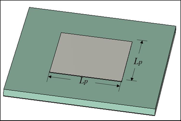
Figure 1: Simulation configuration of the square patch. The size of the patch 6.6.
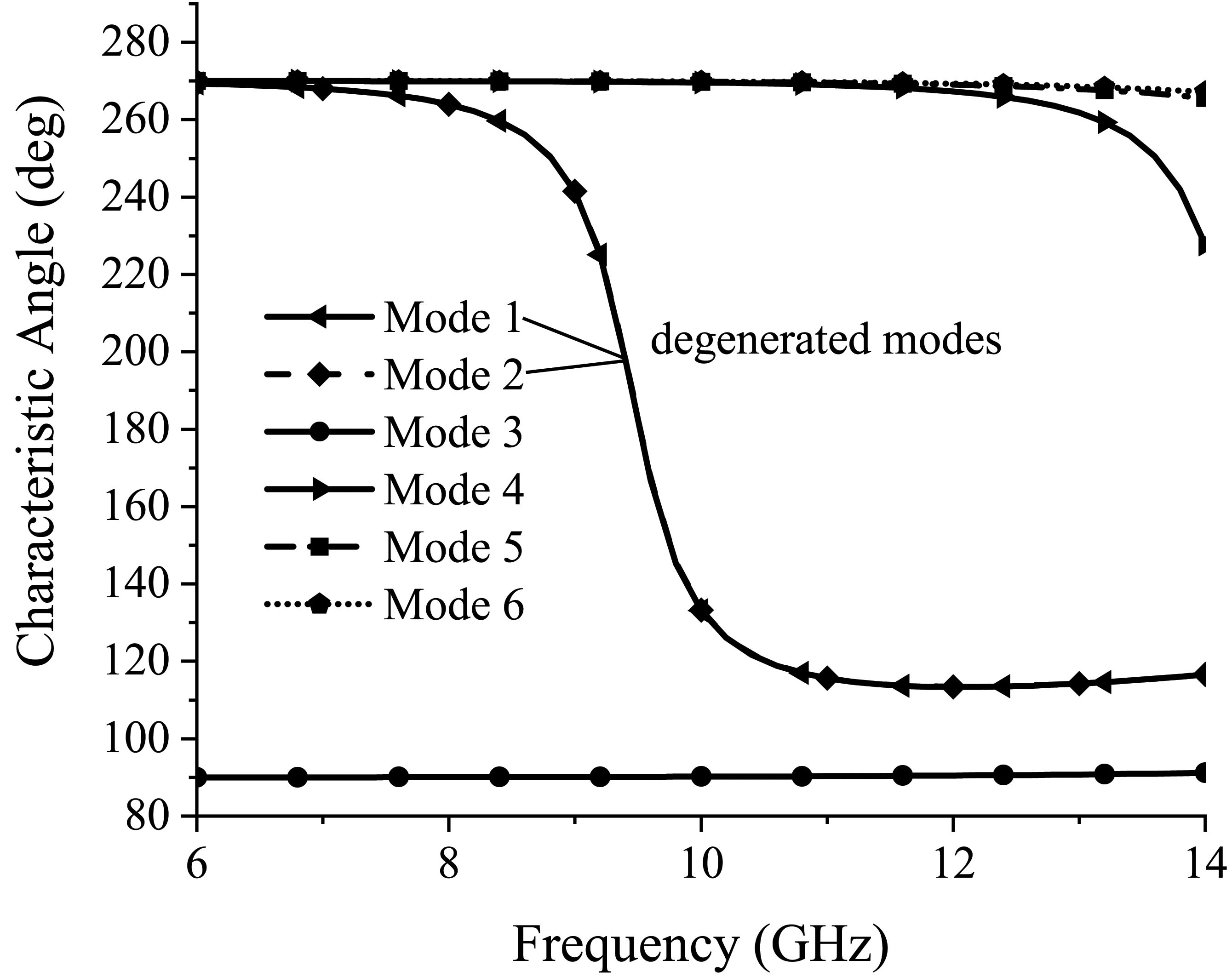
Figure 2: Characteristic angle of the square patch.
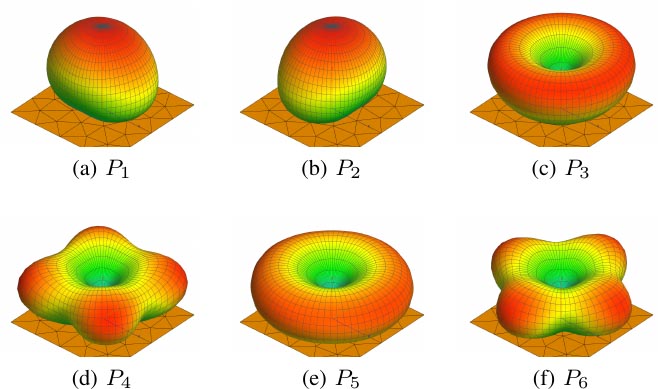
Figure 3: Modal patterns of the square patch.
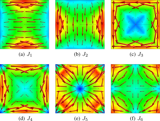
Figure 4: Modal currents of the square patch.
As a wide beamwidth is required, exciting one of the existing modes is not enough. The HPBW of mode 1/2 is only 134.1 in the E-plane and 83.9 in the H-plane. Thus, a modal combination is needed to achieve a wider beamwidth. Several possible combinations of modal patterns are shown in Figure 5. These combined patterns are calculated by a FEKO Lua script that performs the scalar linear combination of modal patterns. In Figure 5(a), we can see that the combined pattern of the two degenerated fundamental modes and is simply a rotation of the modal pattern. This result can be seen as the pattern generated by a combined vector current distribution of the modal currents and .
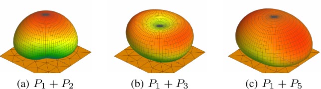
Figure 5: Some combined modal patterns of the square patch.
On the other hand, the combination of a fundamental mode with a perfect unidirectional pattern and a higher-order mode with an omnidirectional pattern leads to a pattern with wide beamwidth, as shown in Figures 5(b) and (c). Obviously the HPBWs of in both E-plane and H-plane are wider than , as the maximal direction of the omnidirectional pattern of is closer to the horizontal plane. The simulated E- and H-plane patterns are shown in Figure 6. The HPBW of E- and H-plane patterns are 170.2 and 156.2, with increases of 36.1 and 72.3 in both E- and H-planes, respectively. Due to the simulation configuration of infinite ground, the radiation patterns are restricted above the ground plane; thus, the HPBW cannot exceed 180.

Figure 6: Normalized E-plane and H-plane patterns of .
To summarize, with the combination of an omnidirectional pattern, a pattern with a wider beamwidth can be achieved. The only problem is to excite both the fundamental and the higher-order omnidirectional modes at the same time. It is difficult to excite both mode 1 and mode 5 properly, as mode 5 resonates at a far high frequency. Thus, the antenna structure should be changed to let both modes resonate at the desired frequency. In Section III, we propose a wide-beam metasurface antenna using the illustrated method.
III. WIDE-BEAM METASURFACE ANTENNA DESIGN
A. Characteristic mode analysis
To design a wide-beam antenna, a metasurface composed of 33 square patches is used as the radiating structure, as shown in Figure 7. The CMA is performed on the metasurface over an infinite grounded substrate. All the modal characteristics are calculated under the commercial software Altair FEKO [22]. Some important modal patterns of the metasurface are shown in Figure 8.
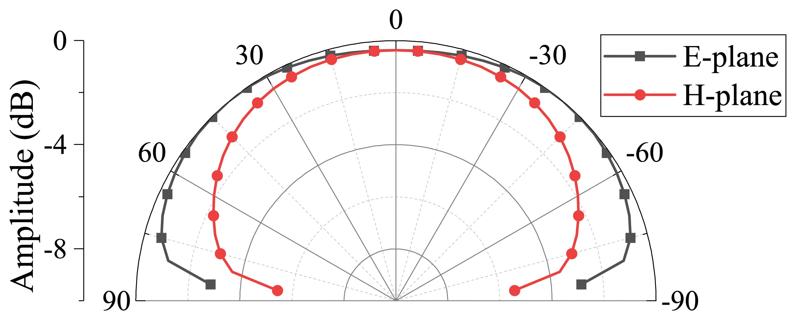
Figure 7: Characteristic angle plot of the 33 metasurface. 6.4 mm, 1.2 mm.
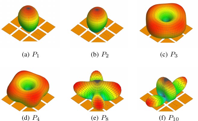
Figure 8: Some modal patterns of the 33 metasurface.
Modes 1 and 2 are degenerated fundamental modes of the 33 metasurface. They are horizontally polarized (TM) and vertically polarized, respectively (TM). mode 3 is a mode with converging or diverging currents, whose pattern is omnidirectional but not as uniformly as the corresponding mode of a square patch. Mode 4 is also an omnidirectional mode, but its modal current is more irregular and harder to exploit. Other modes are less important in generating a radiation pattern with high quality. For example, the two third-order modes shown in Figures 8(e) and (f) have relatively larger sidelobes which can only cause distortions in the resulting pattern. As discussed earlier in Section II, a wide-beam pattern is achieved by combining a unidirectional mode and an omnidirectional one. In this case, mode 1 (or mode 2) and mode 3 are chosen to be excited. The combination effect can be shown in Figure 9. The resulting HPBWs in E- and H-planes are 141.3 and 140.7. Thus, the metasurface is suitable for a wide-beam antenna.
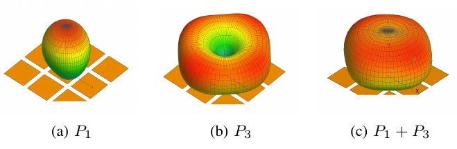
Figure 9: Modal pattern combination of the 33 metasurface.
The corresponding characteristic currents of the metasurface are shown in Figure 10. To excite two modes at the same time, we use the superposition principle. First, the feeding networks that excite single mode 1 and mode 3 are designed separately, and then a divider is designed to combine two feeding networks. These works are expressed in detail in the following sections.
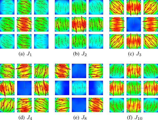
Figure 10: Some modal currents of the 33 metasurface.
B. Design of unidirectional mode antenna
The modal currents of mode 1 in Figure 10(a) are to be excited. The currents on nine subpatches are all parallel to the x-axis, along one edge of each patch. Therefore, the coupling slot is placed under the center of the metasurface perpendicular to the currents, in order to excite the fundamental mode. From Figure 11, the comparison between the modal and the excited currents and patterns show that mode 1 is successfully excited. The simulated gain of the antenna is 9.77 dBi at , but when 60, the gain is under 0 dBi, which can hardly be used in wide-beam applications.
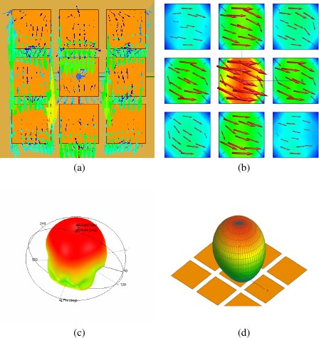
Figure 11: The comparison between excited currents and modal currents of unidirectional mode 1. (a) Excited currents. (b) Modal currents . (c) Excited pattern. (d) Modal pattern .
C. Design of omnidirectional mode antenna
However, the higher-order omnidirectional mode is harder to exploit. The surface currents of mode 3 are not uniform, and they all point to the center. Compared to the surface currents of other modes, the current directions on the four corner patches are unique. Aiming at the corner patches of the metasurface, the feeding slot is designed to be a ring cut into four pieces. Due to the relative symmetric positions of the corner patches, the modal currents on the corner patches are nearly identical in magnitude. So, the exciting magnitude and phase of the feeding network should be the same. For simplicity, a simulation model with two ports and two 1-to-2 dividers are used, as shown in Figure 12(c).
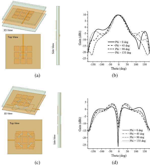
Figure 12: Simulation configuration and gain of the metasurface antenna with mode 1 and mode 3 excited individually. (a) Simulation configuration of the excited mode 1. (b) Gain of the excited mode 1. (c) Simulation configuration of the excited mode 3. (d) Gain of the excited mode 3.
The simulation results of the excited omnidirectional mode are shown in Figure 13. The results have shown that the omnidirectional mode is excited successfully by the feeding network. Note that the pattern of the excited mode can have beams greater than 90 and less than 90 because of finite ground.
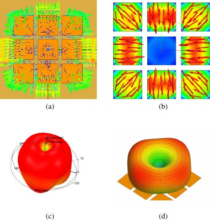
Figure 13: The comparison between excited currents and modal currents of unidirectional mode 3. (a) Excited currents. (b) Modal currents . (c) Excited pattern. (d) Modal pattern .
D. Design of wide-beam antenna with combined modes
As analyzed in Section II, a wide-beam pattern can be achieved by combining mode 1 and mode 3. Thus, the desired wide-beam pattern can be obtained by combining the feeding networks in Sections III.B and III.C. To combine the two feeding networks, an unequal three-way power divider is needed. The proposed feeding network is shown in Figure 14(b). The omnidirectional pattern is excited by four symmetric slots with the same magnitude and phase; therefore, the two corresponding ports should have the same magnitude and phase output. The power divider is evolved from a normal two-way divider with a coupled microstrip between the branches, as shown in Figure 14(a). Power flows into Port 2 by coupling between Port 2 and Port 3/4. To further enhance the power flowing into Port 2, a connection is added to Port 2, as shown in Figure 14(b). The simulated S parameters of the divider are shown in Figure 15. The magnitude ratio between and is 1.1:1 and the phase difference is relatively stable within 911 GHz.
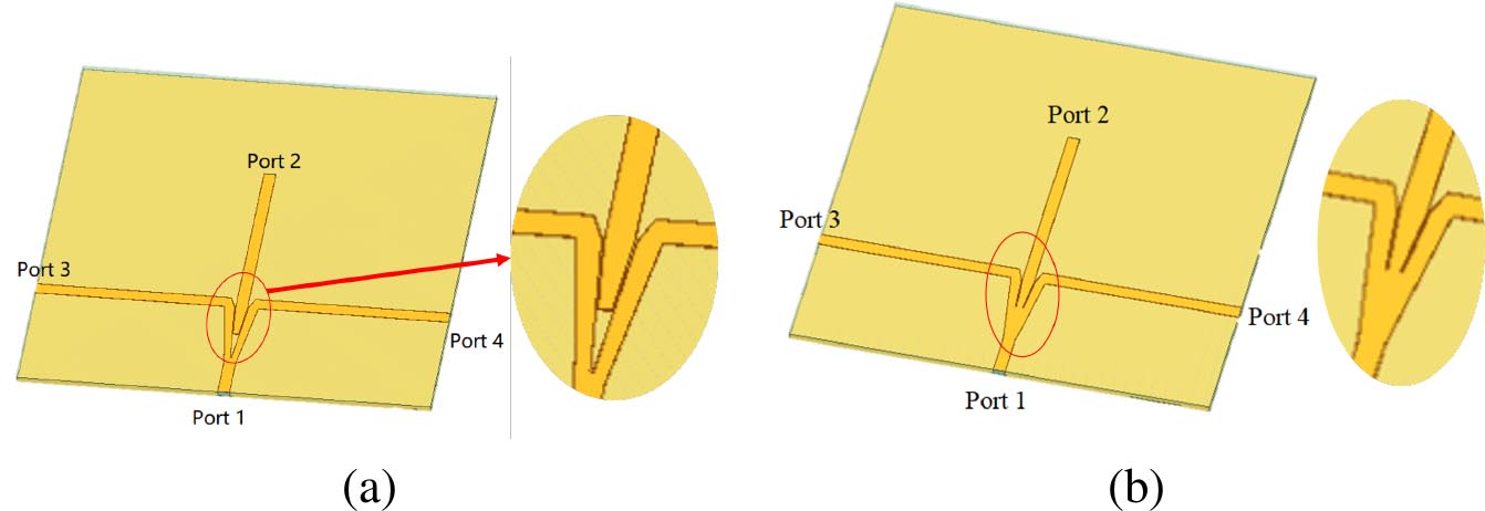
Figure 14: Power divider configuration of the proposed antenna. (a) Divider 1. (b) Proposed divider.
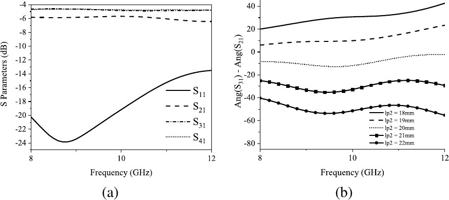
Figure 15: S parameters of the unequal power divider. (a) Magnitudes of , , , and . (b) Phase difference between and with varied length of the microstrip line connected to port 2.
The configuration of the proposed antenna is shown in Figure 16. The feeding network is a combination of the three-way unequal power divider and the feeding networks of the individually excited modes. According to the superposition principle, the result of the combined feeding network can be seen as a linear combination of the two antennas in Sections III.B and III.C. The amplitude of the combination is determined by the unequal power divider and the phase difference between ports can be tuned by the lengths of the feeding branches. The return losses of the combined antenna compared with single mode antennas are shown in Figure 17.
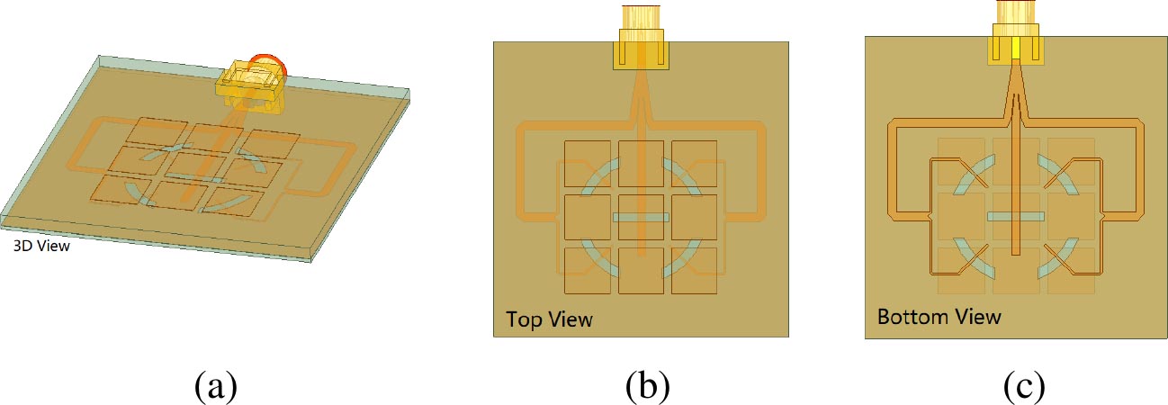
Figure 16: Simulation configuration of the proposed antenna. (a) 3D view. (b) Top view. (c) Bottom view.
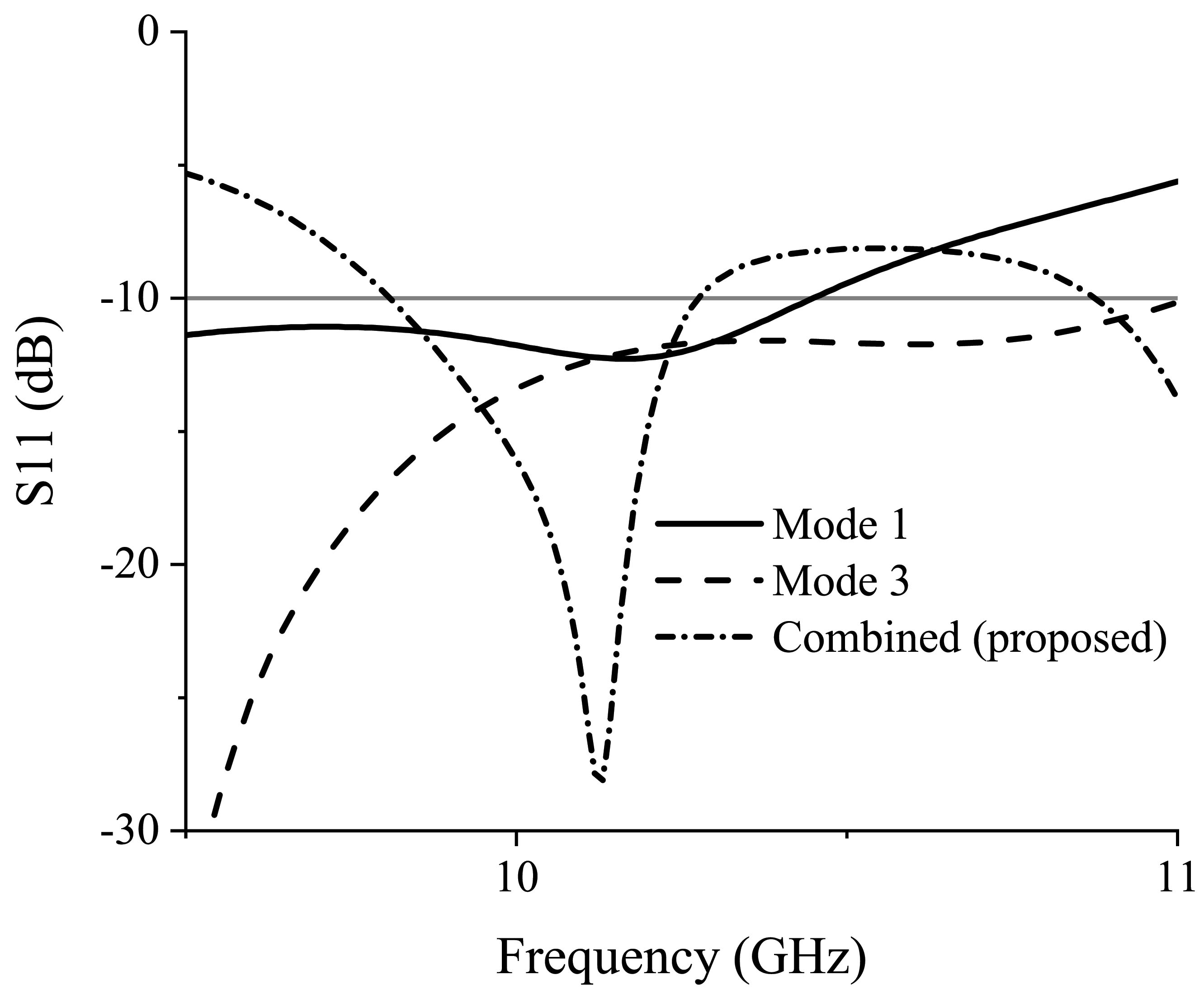
Figure 17: Return loss () of the metasurface antenna.
The simulated radiation pattern is shown in Figure 18. The 3-dB beamwidth of the 45 and 135 planes are 200.9 and 200.6, respectively. The beamwidth of E- and H-planes suffered some loss because of the coupling and unideal characteristics of the combination. On the other hand, the beamwidths in 45 and 135 planes are increased but with an asymmetric pattern. The bandwidth is 9.8110.27 GHz (4.6%). The maximum gain of the wide-beam antenna is 4.25 dBi, which is slightly larger than the omnidirectional antenna. Overall, a wide-beam pattern is successfully obtained.
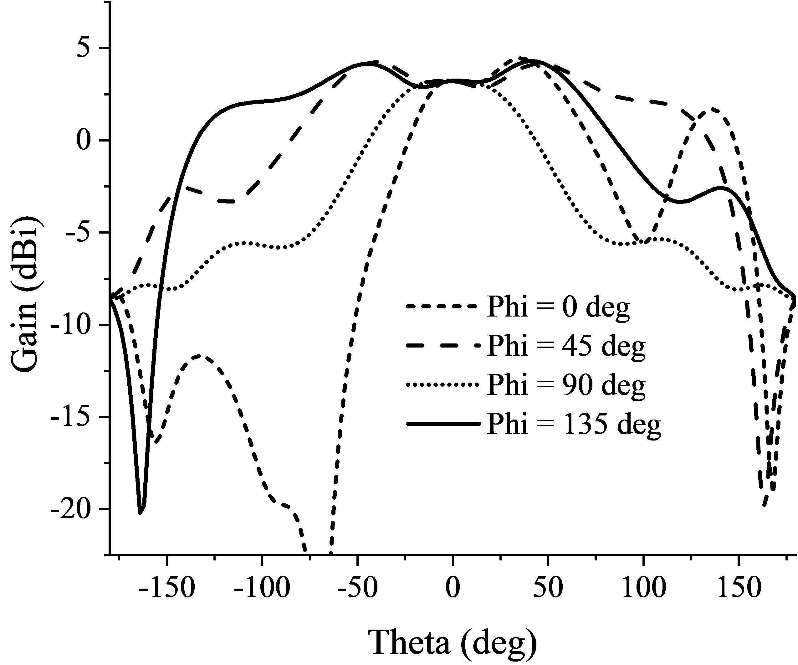
Figure 18: Gain of the proposed antenna.
Comparisons among the proposed antenna and related wide-beam antennas are given in Table 1. As shown in the table, low-profile structures using microstrip structures with grounding vias in [4, 5, 6] and magneto-electric tapered slot antenna in [8] can hardly generate a wide-beam pattern above 140. Structures with wider beamwidths in [3, 7] have higher profiles h0.1. The resulting HPBW is larger than most of the structures. Compared with the dielectric resonator antenna (DRA) in [7], metasurface structures based on microstrips are easy to fabricate and have smaller size.
Table 1: Comparisons among the proposed metasurface antenna and related antennas
| Ref | Type | Size() | HPBW (E-/H-plane) | Ground size (mm) | HPBW/ground |
| size E-/H-plane) (/mm) | |||||
| [1] | MS ring | 0.540.54 0.11 | 6868 | ||
| [3] | MS | 0.630.63 0.21 | 2727 | ||
| [4] | MS | 1.171.870.03 | 125200 | ||
| [5] | MS | 0.520.520.03 | 32.132.1 | ||
| [6] | MS | 0.190.190.07 | 170170 | ||
| [7] | DRA | 2.02.00.16 | 4040 | ||
| [8] | ME TSA | 0.730.670.03 | |||
| This work | MTS | 1.41.40.07 |
() |
4242 |
() |
V. CONCLUSION
A low-profile wide-beam metasurface antenna for detection purpose has been proposed. The 3-dB beamwidth of the 45 and 135 planes are 200.9 and 200.6, respectively. The maximum gain of the wide-beam antenna is 4.25 dBi. The results have shown that the proposed antenna is capable of detection applications near 10 GHz.
ACKNOWLEDGEMENT
This work is supported by the project of 61971051 from the National Natural Science Foundation of China (NSFC).
REFERENCES
[1] Z. Pan, W. Lin, and Q. Chu, “Compact wide-beam circularly-polarized microstrip antenna with a parasitic ring for cnss application,” IEEE Transactions on Antennas and Propagation, vol. 62, no. 5, pp. 2847–2850, 2014
[2] C. Yu, E. S. Li, H. Jin, Y. Cao, G. Su, W. Che, and K. Chin, “24 ghz horizontally polarized automotive antenna arrays with wide fan beam and high gain,” IEEE Transactions on Antennas and Propagation, vol. 67, no. 2, pp. 892–904, 2019.
[3] G. Yang, J. Li, D. Wei, S. Zhou, and J. Yang, “Broadening the beamwidth of microstrip antenna by the induced vertical currents,” IET Microwaves, Antennas Propagation, vol. 12, no. 2, pp. 190–194, 2018.
[4] N. Liu, S. Gao, L. Zhu, L. Ji, L. Yang, and H. Zheng, “Low profile microstrip patch antenna with simultaneous enhanced bandwidth, beamwidth, and cross-polarisation under dual resonance,” IET Microwaves, Antennas Propagation, vol. 14, no. 5, pp. 360–365, 2020.
[5] J. Ou, S. Dong, J. Huang, X. Y. Zhang, W. Che, and Q. Xue, “A compact microstrip antenna with extended half-power beamwidth and harmonic suppression,” IEEE Transactions on Antennas and Propagation, vol. 68, no. 6, pp. 4312–4319, 2020.
[6] Y. He and Y. Li, “Dual-polarized microstrip antennas with capacitive via fence for wide beamwidth and high isolation,” IEEE Transactions on Antennas and Propagation, vol. 68, no. 7, pp. 5095–5103, 2020.
[7] N. Yang, Z. Weng, L. Wang, and T. Liao, “A hybrid dual-mode dielectric resonator antenna with wide beamwidth,” International Journal of RF and Microwave Computer-Aided Engineering, vol. 30, no. 10, p. e22337, 2020. [Online]. Available: https://onlinelibrary.wiley.com/doi/abs/10.1002/mmce.22337
[8] K.-W. Yang, F.-S. Zhang, C. Li, G. Zhao, and F. Zhang, “A wideband planar magneto-electric tapered slot antenna with wide beamwidth,” International Journal of RF and Microwave Computer- Aided Engineering, vol. 29, no. 11, p. e21910, 2019. [Online]. Available: https://onlinelibrary.wiley.com/doi/abs/10.1002/mmce.21910
[9] R. J. Garbacz, “Modal expansions for resonance scattering phenomena,” Proceedings of the IEEE, vol. 53, no. 8, pp. 856–864, 1965.
[10] R. Harrington and J. Mautz, “Theory of characteristic modes for conducting bodies,” IEEE Transactions on Antennas and Propagation, vol. 19, no. 5, pp. 622–628, 1971.
[11] R. Harrington and J. Mautz, “Computation of characteristic modes for conducting bodies,” IEEE Transactions on Antennas and Propagation, vol. 19, no. 5, pp. 629–639, 1971.
[12] M. Cabedo-Fabres, E. Antonino-Daviu, A. Valero-Nogueira, and M. F. Bataller, “The theory of characteristic modes revisited: A contribution to the design of antennas for modern applications,” IEEE Antennas and Propagation Magazine, vol. 49, no. 5, pp. 52–68, 2007.
[13] F. H. Lin and Z. N. Chen, “Low-profile wideband metasurface antennas using characteristic mode analysis,” in IEEE Transactions on Antennas and Propagation, vol. 65, no. 4, pp. 1706–1713, April 2017, doi: 10.1109/TAP.2017.2671036.
[14] J. Lin and Q. Chu, “Increasing bandwidth of slot antennas with combined characteristic modes,” IEEE Transactions on Antennas and Propagation, vol. 66, no. 6, pp. 3148–3153, 2018.
[15] Y. Chen and C. Wang, “Characteristic-mode-based improvement of circularly polarized u-slot and e-shaped patch antennas,” IEEE Antennas and Wireless Propagation Letters, vol. 11, pp. 1474–1477, 2012.
[16] Y. Luo, Z. N. Chen, and K. Ma, “Enhanced bandwidth and directivity of a dual-mode compressed high-order mode stub-loaded dipole using characteristic mode analysis,” IEEE Transactions on Antennas and Propagation, vol. 67, no. 3,pp. 1922–1925, 2019.
[17] T. Li and Z. N. Chen, “A dual-band metasurface antenna using characteristic mode analysis,” IEEE Transactions on Antennas and Propagation, vol. 66, no. 10, pp. 5620–5624, 2018.
[18] S. Liu, D. Yang, and J. Pan, “A low-profile broadband dual-circularly polarized metasurface antenna,” IEEE Antennas and Wireless Propagation Letters, vol. 18, no. 7, pp. 1395–1399,2019.
[19] T. Li and Z. N. Chen, “Shared-surface dual-band antenna for 5g applications,” IEEE Transactions on Antennas and Propagation, vol. 68, no. 2,pp. 1128–1133, 2020.
[20] F. H. Lin and Z. N. Chen, “A method of suppressing higher order modes for improving radiation performance of metasurface multiport antennas using characteristic mode analysis,” IEEE Transactions on Antennas and Propagation, vol. 66, no. 4, pp. 1894–1902, 2018.
[21] S. Rao, D. Wilton, and A. Glisson, “Electromagnetic scattering by surfaces of arbitrary shape,” IEEE Transactions on Antennas and Propagation, vol. 30, no. 3, pp. 409–418, 1982.
[22] D. J. Ludick, E. Lezar, and U. Jakobus, “Characteristic mode analysis of arbitrary electromagnetic structures using feko,” in 2012 International Conference on Electromagnetics in Advanced Applications, 2012, pp. 208–211.
BIOGRAPHIES

Shizhe Zhao received the B.S. degree in communication engineering from the Beijing University of Posts and Telecommunications, Beijing, China, in 2019. He is currently working toward the M.S. degree in electronic engineering from the Beijing University of Posts and Telecommunications.
His research interests include but not limited to theory of characteristic modes and millimeter wave antennas.

Xiuping Li received the B.S. degree from Shandong University, Jinan, China, in 1996 and the Ph.D. degree from the Beijing Institute of Technology, Beijing, China,in 2001.
From 2001 to 2003, she was with the Positioning and Wireless Technology Center, Nanyang Technological University, Singapore, where she was a Research Fellow and involved in the research and development of RFID system. In 2003, she was a Research Professor with Yonsei University, Seoul, South Korea. Since 2004, she has been with the Beijing University of Posts and Telecommunications, Beijing, China, as an Associate Professor and was promoted to Professorin 2009.
Dr. Li has been selected into the New Century Excellent Talents Support Plan in National Ministry of Education and the Beijing Science and Technology Nova Support Plan in 2007 and 2008, respectively. She won the second prize of the Progress in Science and Technology of China Institute of Communications and the Excellent Achievements in Scientific Research of Colleges and Universities in 2015 and 2018, respectively. She is the author of four books, over 100 journal and conference papers. She is also awarded more than 20 PRC patents. Her current research interests include millimeter-wave antennas, THz antennas, RFID systems, and MMIC design.

Yongxin Chen received the B.S. degree in electronic information science and technology from the Nanjing University of Aeronautics and Astronautics, Nanjing, China, in 2015. He is currently working toward the M.S. degree in electronic engineering with the Beijing University of Posts and Telecommunications, Beijing, China.
His current research interests include characteristic modes theory.

Wenyu Zhao received the B.S. degree from the Beijing University of Posts and Telecommunications, Beijing, China, in 2018. He is currently working toward the Ph.D. degree with the School of Electronic Engineering and the Beijing Key Laboratory of Work Safety Intelligent Monitoring, Beijing University of Posts and Telecommunications.
His current research interests include dual-polarized antennas, millimeter-wave antennas, and reflect array antennas.

Zihang Qi received the B.E. degree in electronic and information engineering from China Three Gorges University, Yichang, China, in 2013, and the Ph.D. degree in electronic science and technology from the Beijing University of Posts and Telecommunications, Beijing, China, in 2019.
He is currently an Associate Research Fellow with the Beijing University of Posts and Telecommunications. His current research interests include OAM antennas, millimeter-wave/THz antennas, and microwave filters.
Dr. Qi was a recipient of the 2018 National Scholarship of China for Doctoral Students.
ACES JOURNAL, Vol. 37, No. 1, 41–49.
doi: 10.13052/2022.ACES.J.370105
© 2021 River Publishers