Design of Electronically Controlled Filter Power Divider Based on Liquid Crystal
Wenjie Shen, Ying Han, Weirong Chen, Di Jiang, Sha Luo, and Tianming Bai
1School of Electrical Engineering, Southwest Jiaotong University, Chengdu 610031, China
29788165@qq.com, hanying@swjtu.edu.cn, wrchen@swjtu.edu.cn
2China Railway Engineering Consulting Group Co., Ltd., Beijing 100055, China
3School of Information and Communication Engineering, University of Electronic Science and Technology of China, Chengdu 611731, China
dijiang@uestc.edu.cn, luosha109@163.com, tianyumingfeng@163.com
Submitted On: July 23, 2021; Accepted On: December 12, 2021
Abstract
The wireless communication system is one of the most important facilities of fuel cell hybrid power tram (FCHPT), which provides a strong guarantee for efficient and safe operation. As an indispensable part of the RF front-end of the transmitter and receiver, the miniaturization and high-performance trends of filtering power dividers are becoming evident. Based on the principle of filter power divider, a capacitor loaded power divider filter is designed and fabricated in this paper. The center frequency of the designed power divider filter is 30 GHz, the return loss S is less than 10 dB in the range from 29.2 to 31.6 GHz, and the insertion losses S and S are less than 5.3 dB. The frequency shift of 1.8 GHz can be achieved by changing the dielectric constant of the liquid crystal with an applied bias voltage, which can be used in millimeter wave communication system.
Keywords: Electronically controlled tuning, filter power divider, liquid crystal material.
I. INTRODUCTION
Fuel cells as a promising technology that provide electrical power with high efficiency, less noise, and near-zero emissions have been successfully used in vehicle, rail traffic, ship, and distributed generation. Fuel cell hybrid power tram (FCHPT) is a new type of urban rail transit locomotive, which has been widely studied and successfully applied in the world. The wireless communication system is one of the most important facilities of FCHPT, which is the core guarantee to ensure the safe, reliable, and efficient operation of the tram.
In the wireless communication system of FCHPT, the filtering power divider is an indispensable part of the RF front-end of the transmitter and receiver. The filter can let the desired signal through and suppress the spurious signal, while the power divider can realize the distribution and synthesis of power [1, 2]. In modern wireless communication systems, these two devices are generally designed independently and then cascaded by additional matching networks or transmission lines. The traditional design method makes the circuit have a larger physical size, and the cascade between devices will introduce additional mismatch and loss. The characteristics of filter power divider are mainly determined by the design of filter. The filter with multi-frequency band can save space and meet the needs of most work [3], but the working frequency band is often fixed after the structure is determined. As an extension of multi-band filter, the adjustable filtering power divider has the characteristics of high integration, dynamic frequency selection, low loss, and so on [4]. The technology is to realize reconfigurable performance mainly including PIN [5], varactor tuning technology [6], ideal switches [7, 8], MEMS system tuning technology [9, 10], graphite [11], iron or ferrite tuning technology [12, 13], and so on. In addition, as a new type of electromagnetic material, liquid crystal material holds the characteristics of anisotropy of dielectric constant, stable electromagnetic performance, and low loss. Liquid crystal tuned microwave passive devices are based primarily on liquid crystal electromagnetic effect. When the low frequency bias voltage is applied to it, under the action of the electric field, the director of the liquid crystal molecule is driven to be consistent with the bias voltage of the external electric field, which changes the distribution state of the liquid crystal pointing vector in space. At the same time, for the electromagnetic wave with a certain polarization direction with liquid crystal as the medium, the change of the spatial director of the liquid crystal means that the refractive index of the incident wave is changed, so as to modulate the transmission state of the electromagnetic wave transmitted in the liquid crystal. At present, researchers at home and abroad have carried out a lot of research work on passive devices based on liquid crystal materials, such as tunable phase shift [14], adaptive filter [15], tunable planar reflection array antenna [16, 17], phased array antenna [18–20], and frequency selective surface [21–23]. Liquid crystal tunable technology has great application potential and development prospects.
The traditional filter resonant structures include end coupling [24], parallel coupling line [25], comb line [26], hairpin type [27], cross toe type [28], etc. All of the above structures are realized by coupling lines, and the input and output of traditional coupling line structures are not on the same straight line. The end coupling size is usually larger, comb line, hairpin type, or cross toe type, and other structures require high machining accuracy, especially in the millimeter wave band. For the purpose of integration and miniaturization of wireless communication system, an electronically controlled adjustable filtering power divider is proposed in this paper. A capacitive electromagnetic cross-coupling resonator structure is designed, and the capacitive coupling resonator is integrated into the two output terminals of the first-order Wilkinson power divider. Then, by using the liquid crystal material and electrifying the electrodes on the upper and lower surface of the liquid crystal. The liquid crystal molecular orientation will change with the voltage value, which changes the dielectric constant of the liquid crystal material, so as to tune the central frequency of the filtering power divider. Its structure is relatively simple, which meets the requirements of broadband miniaturization of current electronic communication technology, and adapts to a wider range of application scenarios.
II. THEORY AND DESIGN
A. Capacitor loaded power divider bandpass filter
Ideally, the structure of the capacitive loaded lossless transmission line resonator is shown in Figure 1. Denoting the transmission coefficient by , where is the angular frequency, L and C are expressed as distributed series inductors and parallel capacitors, respectively. If the capacitance C becomes larger in the circuit, transmission coefficient will decrease, and the slow-wave effect will appear, thus reducing the size of the circuit. If the capacitance C increases periodically, it can reduce the circuit size and have band-stop characteristics. It has a good effect on the suppression of some frequencies. Coupling equivalent circuits of two resonators are shown inFigure 2.

Figure 1: Ideally loaded capacitive transmission line resonator.
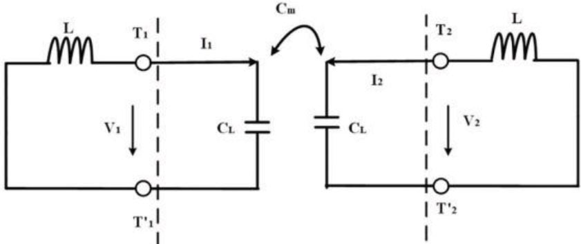
Figure 2: Coupling equivalent circuit of two resonators.
By using the two-port network theory to analyze the coupling between two resonators, the capacitive coupling between stages can be further equivalent to an admittance converter, and the equivalent circuit of interstage coupling is shown in Figure 3.
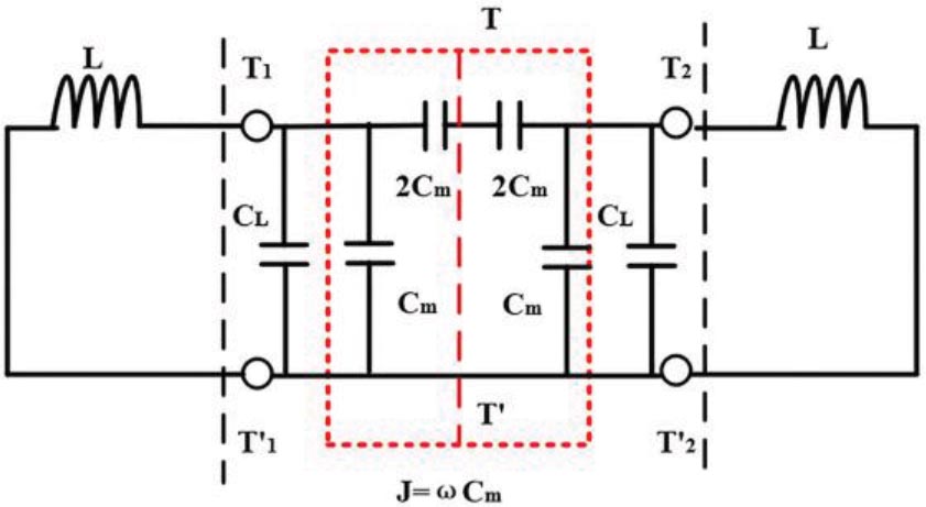
Figure 3: Coupling equivalent circuit of two resonators.
If T-T’ is equivalent to an electric wall, the resonant frequency is
| (1) |
If T-T’ is equivalent to a magnetic wall, the resonant frequency is
| (2) |
Therefore, the coupling coefficient between the two resonators is
| (3) |
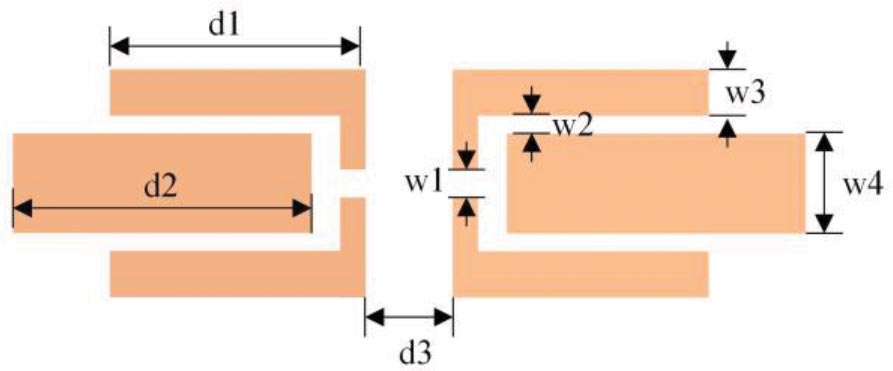
Figure 4: The structure of capacitor loaded power divider bandpass filter.
Table 1: Design parameters and their values
| Parameters | Value (mm) |
|---|---|
| d1 | 2.7 |
| d2 | 3.7 |
| d3 | 0.15 |
| w1 | 0.15 |
| w2 | 0.07 |
| w3 | 0.27 |
| w4 | 1.07 |
A capacitor loaded filter coupled with a resonant unit, as shown in Figure 4, is adopted. In the design of this structure, the multipath effect caused by the coupling between multiple resonators makes the signal synthesize with the same amplitude and phase at the output port. Through two identical coupling paths, not only compact structure can be realized but also lower loss can be realized. Based on this structure, modeling and simulation are carried out in HFSS. The specific design parameters are shown in Table 1.
The filter uses a Rogers 5880 substrate with a thickness of h = 0.254 mm, with a relative dielectric constant of 2.2 and a dielectric loss tangent of 0.0009. After the above theoretical analysis, through the loading capacitance introduced by the microstrip gap, the S parameter of the filter is obtained according to the parameters of Table 1. The results of equivalent circuit model and HFSS simulation model are compared as shown in Figure 5. Considering the limit of actual fabricated accuracy, the simulation results in HFSS are poor compared with the ideal circuit simulation results. But they still meet the requirements and are basically consistent with the expectation, which verifies the effectiveness of the circuit. In the HFSS simulation, the central frequency is at 30.9 GHz, the insertion loss in the passband is less than 1.4 dB, and the return loss is greater than 13 dB.
B. Filter-based Wilkinson power divider
The Wilkinson power divider’s function is to distribute the input signal equally or unequally to each output port and maintain the same output phase. Although the ring has similar functions, the Wilkinson power divider has a broader bandwidth in the application.
The circuit structure of the microstrip Wilkinson power divider is shown in Figure 6. Among them, the characteristic impedance of the input port is . According to the quarter wavelength impedance transformation theory, the electrical length of the two branch microstrip lines is , the characteristic impedance is , and the characteristic impedance of the output port is .
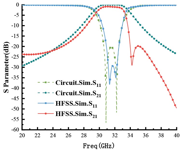
Figure 5: Comparison of S parameter simulation results.
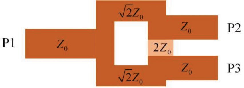
Figure 6: Circuit structure of microstrip Wilkinson power divider.
The characteristic impedance of the microstrip lines is 50 . The value of isolation resistance can be obtained from the following formula:
| (4) |
where , and when the power is evenly distributed, k is 1, then R = 2 Z.
The linewidth of 50 mounted microstrip lines can be calculated by the empirical formula
| (5) |
where h is the height of the substrate, t is the line height, and w is the width of the microstrip lines.
When the input signal enters from P1, P2 and P3 have equal amplitude and in-phase output. The power divider is designed based on microstrip line; so transmission mode is quasi-TEM mode. The simulation results of the frequency response of the first-order Wilkinson power divider are shown in Figure 7, including isolation and transmission characteristics. As can be seen in Figure 7, the energy is evenly divided within the effective frequency band, the transmission attenuation of port is 4 dB, the curves of S and S are basically consistent, and the isolation of ports 2 and 3 is greater than 15 dB.

Figure 7: Simulation results of the first-order Wilkinson power divider.
C. Adjustable filter power divider
The frequency selection performance of the filtering power divider mainly depends on the filter. The loading capacitor filter introduced above is cascaded at the two outputs of the first-order Wilkinson power divider to form the filtering power divider. The overall structure model is shown in Figure 8. The size of the whole structure of the filtering power divider is 35 mm 20 mm. Two layers of Rogers 5880 dielectric substrate with a thickness of 0.254 mm and a dielectric constant of 2.2 are used, and the second layer substrate is slotted in the middle to fill the liquid crystal material. The liquid crystal block area is 22 mm 6 mm, and the thickness is set to 0.254 mm. The frequency response results are shown in Figure 8. The center frequency of the filter is 30 GHz, the return loss S is less than 10 dB in the range of 29.0231.64 GHz, and the insertion losses S and S are less than 5 dB. It can be seen from Figure 9 that the designed filtering power divider achieves equal power division performance in the operating frequency band and has the same amplitudeand phase.
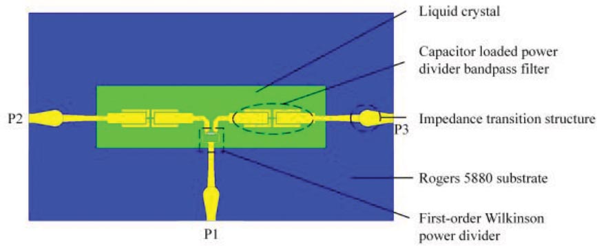
Figure 8: Structure of adjustable filtering power divider.
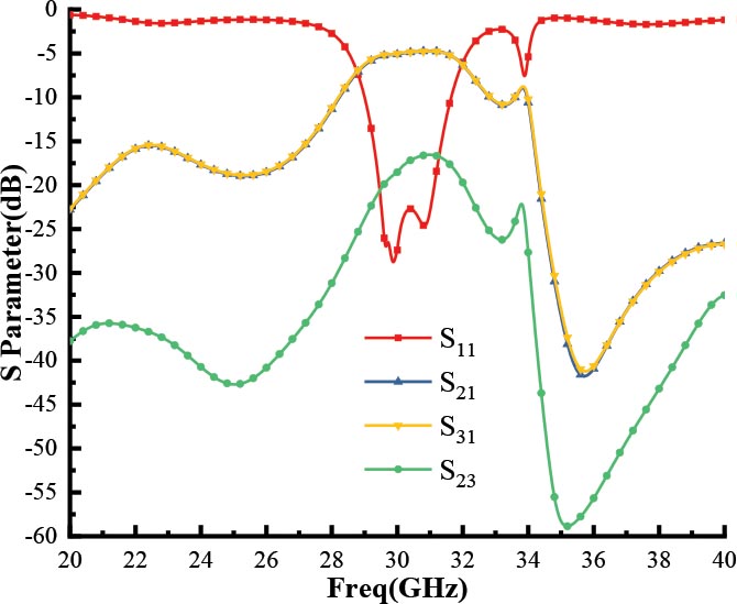
Figure 9: Simulation results of S parameter.
Liquid crystal is an electromagnetic tuning material. As shown in Figure 10(a), with the different applied bias voltage, the molecular orientation in it will change, resulting in the change of dielectric constant. And then, the corresponding resonant frequency of microstrip lines with the same size will change, that is, frequency reconfiguration is realized. When the liquid crystal molecule is perpendicular to the direction of the electric field, the corresponding dielectric constant is , the liquid crystal molecule is parallel to the direction of the electric field, and the corresponding dielectric constant is . In the simulation, the liquid crystal is set as a new material and its dielectric constant is set as a variable for simulation. In the actual measurement, the metal of the filter layer is grounded and the metal base is loaded with bias voltage, as shown in Figure 10(b). The dielectric constant of liquid crystal is adjusted by adjusting the bias voltage, so as to realize the frequency reconfigurable characteristics of filter power divider.
Then the dielectric constant of the liquid crystal varies uniformly in the range of 2.22.8. As shown in Figure 11, the center frequency of the passband of the filter power divider moves from 30 to 28.1 GHz to achieve the 1.9-GHz frequency shift.
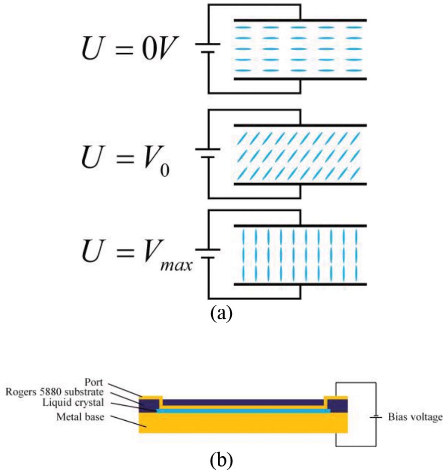
Figure 10: Schematic diagram of liquid crystal bias voltage control. (a) Tuning process. (b) Bias voltage loading structure.
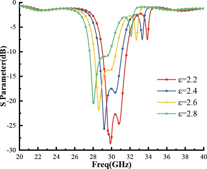
Figure 11: Simulation results of S tuning.
III. RESULTS AND DISCUSSION
To verify the feasibility of the filtering power divider, it is processed and tested according to the structure size of the filtering power divider. The prototype of the filtering power divider is shown in Figure 12. The circuit structure shown in Figure 12 is attached to the lower surface of the upper dielectric substrate in the form of inverted microstrip, and the dielectric constant of the liquid crystal is controlled by the bias voltage between the inverted microstrip patch and the metal base, to realize the change of the resonance point. The orientation of liquid crystal molecules is matched by coating a layer of polyimide film on the metal copper foil of the filter power splitter. After completing the phase matching, the direction of all liquid crystal molecules is perpendicular to the electric field.
The test platform is shown in Figure 13, which includes the PNA-X vector network analyzer and function waveform generator. The function waveform signal generator provides 1-KHz low-frequency square wave signal modulation voltage (020 V) for the experiment. The dielectric constant of liquid crystal varies with the applied voltage, but excessive voltage will destroy the internal structure of liquid crystal molecules. Generally, the applied voltage range is 020 V, and its electrical tuning ability can be expressed as follows:
| (6) |
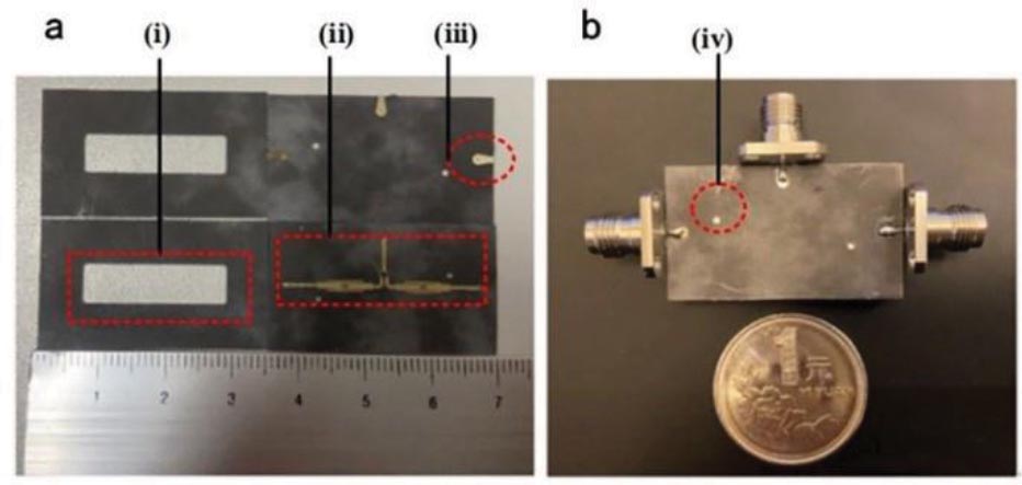
Figure 12: Prototype of adjustable filtering power divider. (a) Layered structure: (i) liquid crystal slot; (ii) inverted microstrip filter; (iii) transition structure. (b) Integral structure: (iv) liquid crystal injection hole.
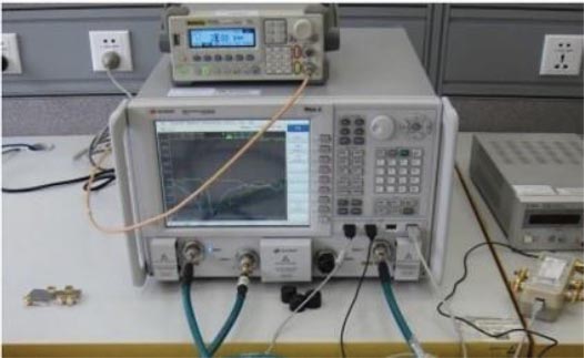
Figure 13: Measurement of power divider filter.
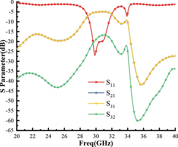
Figure 14: Measurement results of S parameter.
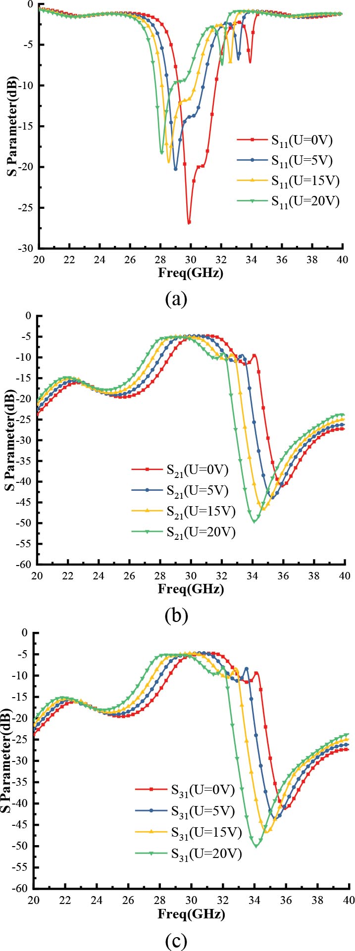
Figure 15: Measurement tuning results of S parameter. (a) S. (b) S. (c) S.
As can be seen from Figure 14, the bandwidth of the filtering power divider is 2.46 GHz, the return loss S is less than 10 dB in the range from 29.2 to 31.6 GHz, and the insertion losses S and S are less than 5.3 dB. It can be seen that the designed filtering power divider achieves equal power division performance in the working frequency band. Then, by changing the voltage range of 020 V at both ends of the liquid crystal, as shown in Figure 15, the center frequency of the passband of the filtering power divider is shifted from 29.9 to 28.1 GHz to achieve 1.8-GHz frequency shift. Compared with the simulation results, the measurement results are slightly worse, which may be due to the generation of some bubbles during liquid crystal filling, which affects the performance, but it is still within the acceptable range. The measurement results show that the proposed liquid crystal filter power divider can realize frequency tuning. The performance comparison with similar power division filters is shown inTable 2.
Table 2: Comparison of proposed work with others
| Tuning | |||
| Ref. | Frequency | Bandwidth | bandwidth |
| (GHz) | (GHz) | (GHz) | |
| [29] | 1.2 | 0.04 | No |
| [30] | 1.4 | 0.2 | No |
| [31] | 1.4 | 0.25 | 0.2 |
| [32] | 1 | 0.2 | 0.4 |
| This work | 30 | 2.46 | 1.8 |
IV. CONCLUSION
In this paper, an electronically controlled filter power divider of FCHPT based on liquid crystal is designed by cascading the Wilkinson power divider with the output port of the filter unit. Compared with most of the low frequency filters, the designed power divider filter integrates power distribution and filtering and can work at 30 GHz. In addition, by changing the voltage value, the liquid crystal pointing vector can be changed, so as to change the effective dielectric constant of the liquid crystal material, and then tune the center frequency of the filter power divider. The tuning bandwidth of the filtering power divider is 1.8 GHz (29.928.1 GHz), and the port isolation is less than 18 dB. In the continuously adjustable range, the maximum insertion loss is 5.3 dB. It realizes dynamic frequency selection and power distribution, effectively simplifies the structure and size of the system, and realizes the miniaturization and lightweight characteristics of the electronic system, thus reducing the cost and suitable for millimeter-wave electronic communication systems.
REFERENCES
[1] R. Gómez-García, L. Yang, J.-M. Muñoz-Ferreras, and W. Feng, “Lossy signal-interference filters and applications,” IEEE Transactions on Microwave Theory and Techniques, vol. 68, no. 2, pp. 516-529, Dec. 2020.
[2] K. Song, F. Xia, Y. Zhou, S. Guo, and Y. Fan, “Microstrip/slotline-coupling substrate integrated waveguide power divider with high output isolation,” in IEEE Microwave and Wireless Components Letters, vol. 29, no. 2, pp. 95-97, Feb.2019.
[3] Y. Li, S. Luo, and W. Yu, “A compact tunable triple stop-band filter based on different defected microstrip structures,” Applied Computational Electromagnetics Society Journal, vol. 33, no. 7, pp. 752-757, Apr. 2018.
[4] P. Wen, Z. Ma, H. Liu, S. Zhu, B. Ren, Y. Song, X. Wang, and M. Ohira, “Dual-band filtering power divider using dual-resonance resonators with ultrawide stopband and good isolation,” in IEEE Microwave and Wireless Components Letters, vol. 29, no. 2, pp. 101-103, Feb. 2019.
[5] E. Abiri, M. R. Salehi, S. Kohan, and M. Mirzazadeh, “Multi-application PIN diode,” 2010 Second Pacific-Asia Conference on Circuits, Communications and System, pp. 60-62, Aug. 2010.
[6] Q. Xiang, Q. Feng, and X. Huang, “Tunable bandstop filter based on split ring resonators loaded coplanar waveguide,” Applied Computational Electromagnetics Society Journal, vol. 28, no. 7, pp. 591-596, Jul. 2013.
[7] Y. Li, W. Li, and W. Yu, “A switchable UWB slot antenna using SIS-HSIR and SIS-SIR for multi-mode wireless communications applications,” Applied Computational Electromagnetics Society Journal, vol. 27, no. 4, pp. 340-351, Apr. 2012.
[8] Y. Li, W. Li, and Q. Ye, “A reconfigurable wide slot antenna integrated with sirs for UWB/multiband communication applications,” Microwave & Optical Technology Letters, vol. 55, no. 1, pp. 52-55, Jan. 2013.
[9] S. Fouladi, F. Huang, W. D. Yan, and R. R. Mansour, “High-Q narrowband tunable combline bandpass filters using MEMS capacitor banks and piezomotors,” IEEE Transactions on Microwave Theory and Techniques, vol. 61, no. 1, pp. 393-402, Jan. 2013.
[10] E. Erdil, K. Topalli, M. Unlu, O. A. Civi, and T. Akin, “Frequency tunable microstrip patch antenna using RF MEMS technology,” in IEEE Transactions on Antennas and Propagation, vol. 55, no. 4, pp. 1193-1196, Apr. 2007.
[11] C. Huang, J. Song, C. Ji, J. Yang, and X. Luo, “Simultaneous control of absorbing frequency and amplitude using graphene capacitor and active frequency-selective surface,” in IEEE Transactions on Antennas and Propagation, vol. 69, no. 3, pp. 1793-1798, Mar. 2021.
[12] J. D. Adam, L. E. Davis, G. F. Dionne, E. F. Schloemann, and S. N. Stitzer, “Ferrite devices and materials,” in IEEE Transactions on Microwave Theory and Techniques, vol. 50, no. 3, pp. 721-737, Mar. 2002.
[13] Q. D. Huang and Y. J. Cheng, “Ferrite-loaded substrate integrated waveguide frequency-agile bandpass filter,” Applied Computational Electromagnetics Society Journal, vol. 31, no. 7, pp. 823-828, Jul. 2016.
[14] B. S.-Y. Ung, X. Liu, E. P. J. Parrott, A. K. Srivastava, H. Park, V. G. Chigrinov, and E. Pickwell-MacPherson, “Towards a rapid terahertz liquid crystal phase shifter: terahertz in-plane and terahertz out-plane (TIP-TOP) switching,” in IEEE Transactions on Terahertz Science and Technology, vol. 8, no. 2, pp. 209-214, March 2018.
[15] D. Jiang, X. Li, Z. Fu, G. Wang, Z. Zheng, T. Zhang, and W.-Q. Wang, “Millimeter-wave broadband tunable band-pass filter based on liquid crystal materials,” in IEEE Access, vol. 8, pp. 1339-1346, Nov. 2020.
[16] G. Perez-Palomino, P. Baine, R. Dickie, M. Bain, J. A. Encinar, R. Cahill, M. Barba, and G. Toso, “Design and experimental validation of liquid crystal-based reconfigurable reflectarray elements with improved bandwidth in F-band,” in IEEE Transactions on Antennas and Propagation, vol. 61, no. 4, pp. 1704-1713,Apr. 2013.
[17] S. Bildik, S. Dieter, C. Fritzsch, W. Menzel, and R. Jakoby, “Reconfigurable folded reflectarray antenna based upon liquid crystal technology,” in IEEE Transactions on Antennas and Propagation, vol. 63, no. 1, pp. 122-132, Jan. 2015.
[18] G. Perez-Palomino, P. Baine, R. Dickie, M. Bain, J. A. Encinar, R. Cahill, M. Barba, and G. Toso, “Design and experimental validation of liquid crystal-based reconfigurable reflectarray elements with improved bandwidth in F-band,” in IEEE Transactions on Antennas and Propagation, vol. 61, no. 4, pp. 1704-1713, Apr. 2013.
[19] R. Reese, E. Polat, H. Tesmer, J. Strobl, C. Schuster, M. Nickel, A. B. Granja, R. Jakoby, and H. Maune, “Liquid crystal based dielectric waveguide phase shifters for phased arrays at W-band,” in IEEE Access, vol. 7, pp. 127032-127041, Sep. 2019.
[20] Y. Zhao, C. Huang, A. Qing, and X. Luo, “A frequency and pattern reconfigurable antenna array based on liquid crystal technology,” IEEE Photonics Journal, vol. 9, no. 3, pp. 1-7, Jun.2017.
[21] W. Hu, R. Dickie, R. Cahill, H. Gamble, Y. Ismail, V. Fusco, D. Linton, N. Grant, and S. Rea “Liquid crystal tunable mm wave frequency selective surface,” IEEE Microwave and Wireless Components Letters, vol. 17, no. 9, pp. 667-669, Sept.2007.
[22] J. A. Bossard, X. Liang, L. Li, S. Yun, D. H. Werner, B. Weiner, T. S. Mayer, A. Diaz, and I. C. Khoo, “Tunable frequency selective surfaces and negative-zero-positive index metamaterials based on liquid crystals,” in IEEE Transactions on Antennas and Propagation, vol. 56, no. 5, pp. 1308-1320, May 2008.
[23] S. N. Novin, S. Jarchi, and P. Yaghmaee,“Tunable frequency selective surface based on IDC-loaded electric-LC resonator incorporated with liquid crystal,” 2017 Conference on Microwave Techniques (COMITE), pp. 1-4, May 2017.
[24] A. Vosoogh, A. A. Brazález, and P. Kildal, “A V-band inverted microstrip gap waveguide end-coupled bandpass filter,” in IEEE Microwave and Wireless Components Letters, vol. 26, no. 4, pp. 261-263, Apr. 2016.
[25] S. Lin, Y. Chen, P. Chiou, and S. Chang, “Tunable Wilkinson power divider utilizing parallel-coupled-line-based phase shifters,” in IEEE Microwave and Wireless Components Letters, vol. 27, no. 4, pp. 335-337, Apr. 2017.
[26] L. Zhou, S. Liu, J. Duan, and M. Xun, “A novel tunable combline bandpass filter based on external quality factor and internal coupling tunings,” Applied Computational Electromagnetics Society Journal, vol. 33, no. 6, pp. 591-596, Jun.2018.
[27] J.-S. Hong and M. J. Lancaster, “Cross-coupled microstrip hairpin-resonator filters,” IEEE Transactions on Microwave Theory and Techniques, vol. 46, no. 1, pp. 118-122, Jan. 1998.
[28] T. Cheng and K. Tam, “A wideband bandpass filter with reconfigurable bandwidth based on cross-shaped resonator,” in IEEE Microwave and Wireless Components Letters, vol. 27, no. 10, pp. 909-911, Oct. 2017.
[29] C. Chen and C. Lin, “Compact microstrip filtering power dividers with good in-band isolation performance,” in IEEE Microwave and Wireless Components Letters, vol. 24, no. 1, pp. 17-19,Jan. 2014.
[30] X. Zhao, L. Gao, X. Y. Zhang, and J. Xu, “Novel filtering power divider with wide stopband using discriminating coupling,” in IEEE Microwave and Wireless Components Letters, vol. 26, no. 8, pp. 580-582, Aug. 2016.
[31] Y.-H. Chun, J.-S. Hong, P. Bao, T. J. Jackson, and M. J. Lancaster, “BST varactor tuned bandstop filter with slotted ground structure,” 2008 IEEE MTT-S International Microwave Symposium Digest, pp. 1115-1118, Jun. 2008
[32] D. Psychogiou, R. Gómez-García, A. C. Guyette, and D. Peroulis, “Reconfigurable single/multi-band filtering power divider based on quasi-bandpass sections,” in IEEE Microwave and Wireless Components Letters, vol. 26, no. 9, pp. 684-686, Sep. 2016.
BIOGRAPHIES
Wenjie Shen received the bachelor’s degree in electrical engineering from Beijing Jiaotong University, Beijing, China, in 2004, and the master’s degree in electrical engineering from Tsinghua University, Beijing, China, in 2013. He is currently working toward the doctor’s degree.
He is currently a Senior Engineer and Vice President of China Railway Engineering Consulting Group Co., Ltd. His research interests include the design of railway and metro traction power supply systems.

Ying Han received the B.S. and Ph.D. degrees from the School of Electrical Engineering, Southwest Jiaotong University, Chengdu, China, in 2013 and 2019, respectively.
He is a Visiting Scholar with the School of Information Technology and Electrical Engineering, University of Queensland, Brisbane, Australia. He is a Senior Member of IEEE and an Assistant Professor with the School of Electrical Engineering, Southwest Jiaotong University. His research interests include optimal control of fuel cell locomotives, energy management of hybrid systems, and optimization and control of integrated energysystems.

Weirong Chen received the B.S. and M.S. degrees in electronic engineering from the Electronic Science and Technology University, Chengdu, China, in 1985 and 1988, respectively, and the Ph.D. degree in power system and its automation from Southwest Jiaotong University, Chengdu, China, in 1998.
He is currently a Senior Visiting Scholar with Brunel University, London, U.K., in 1999. He is an IET Fellow and Professor with the School of Electrical Engineering, Southwest Jiaotong University. His research interests include renewable energy and its applications, fuel cell locomotive technology, and power systemcontrol.

Di Jiang is currently an Associate Professor and Doctoral Advisor of Information and Communication Engineering with the University of Electronic Science and Technology of China, Chengdu, China. He is mainly engaged in broadband reconfigurable microwave devices, array antennas, and other research.

Sha Luo is currently a graduate student of Information and Communication Engineering with the University of Electronic Science and Technology of China, Chengdu, China. He loves learning new knowledge, likes to contact new things, is willing to communicate with people, and have a sense of responsibility. In the graduate stage, he studied in the direction of RF and microwave. His main research topics are reconfigurable antenna and passive components. He designed passive phased array antenna, holographic antenna, phase shifter, filter power divider, microstrip log periodic antenna, waveguide slot antenna, etc.
Tianming Bai is currently a graduate student of Information and Communication Engineering with the University of Electronic Science and Technology of China, Chengdu, China. His main research direction is conformal antenna, reflection array antenna, phased arrayantenna, etc.
ACES JOURNAL, Vol. 37, No. 1, 93–101.
doi: 10.13052/2022.ACES.J.370111
© 2021 River Publishers