A Broadband Dual-Polarized Magneto-Electric Dipole Antenna Element for Low-Frequency Astronomical Arrays
Akila Murugesan, Divya Natarajan, S. Abishek, V. Lingasamy, K. Hariharan, and Krishnasamy T. Selvan
1Department of Electronics and Communication Engineering, Sri Sivasubramaniya Nadar College of Engineering, Kalavakkam 603110, India
selvankt@ssn.edu.in
2Oracle Financial Services Software Limited, Chennai 600086, India
3Johnson Electric Private Limited, Chennai 600123, India
4Sterlite Technologies Limited, Gurgaon 122002, India
5L & T Infotech, Navi Mumbai 400710, India
Submitted On: July 19, 2021; Accepted On: November 25, 2021
Abstract
This paper presents simulation-based design and analysis of a broadband dual-polarized magneto-electric dipole antenna element that can be used to construct VHF astronomical antenna arrays. The antenna consists of two pairs of radiating structures, each fed by a -shaped feeding section. The feeding section and radiating parts are physically disconnected from each other. The antenna is evaluated by simulation, and its 10 dB impedance matching bandwidth ranges from 115 to 340 MHz. The maximum gain of the antenna is about 8 dB over the operating range. Isolation of about 20 dB is observed between the two input ports.
Keywords: Array, astronomy, broadband, dual-polarization, magneto-electric dipole, VHF.
I. INTRODUCTION
Radio astronomy has always been one of the most explored research topics. It deals with the measurement of electromagnetic radiation emitted from cosmic sources, where the emissions are irregularly varying as a function of time. The emissions are spread over a wide range of frequencies from a few MHz to the far-infrared. Since the signals of interest are very weak, antenna arrays are designed and distributed over large effective apertures covering hundreds of meters/kilometers [1]. The first step in the array modeling of an astronomical array is the design of the element. The element design is pretty challenging as it should have a good impedance match and stable gain over a wide range offrequencies.
Various antenna elements have been reported in the literature for astronomical purposes, which include Bowtie antenna, log-periodic dipole array, Vivaldi antenna, parabolic reflector antenna, and magneto-electric dipole (MD) antenna.
Log-periodic antennas [2, 3] are used when simultaneous multi-frequency observations of radio emissions from celestial radio sources must be monitored. But they offer narrow bandwidth and are also susceptible to winds due to their height, especially when designed for low frequencies. Although parabolic reflector antennas play a major role in microwave satellite and space communications, from [4–6], it is noted that these are primarily designed for transmitting and receiving pencil beams. Also, designing a parabolic reflector antenna in the VHF band is a complex process. Other wideband antenna elements like Vivaldi [7, 8] and Bowtie [9], when designed for astronomical purposes, require a complex feeding mechanism that includes the design of baluns for impedance matching. Furthermore, they are usually printed on dielectrics, which reduces the likeliness of being deployed in an outside environment.
A wideband magneto-electric dipole (ME) antenna reported in [10] exhibits wide bandwidth and seems to be appropriate for astronomical arrays considering its metallic construction. It also offers better radiation characteristics such as low cross-polarization and back radiation, symmetric E- and H-plane radiation patterns, and stable gain across the operating band. These are achieved by exciting both electric and magnetic dipoles with suitable amplitudes and phases [11, 12]. A variant of dual-polarized ME antenna reported in [13] combats multipath fading effects and enhances the polarization diversity. Also, the -shaped probe feed of the ME antenna employed in [14] improves the impedance characteristics of the antenna. A dual-band shared-aperture base station antenna array reported in [15] is based on ME elements.
Considering the advantages and performance characteristics of a dual-polarized ME antenna, in this work, a simulation-based modified [16] dual-polarized ME antenna operating over the frequency range of 115–340 MHz is designed. The novelty aspects of the proposed design are: (1) the design of horizontal plates with a curvature at the corners which enhances the impedance match, (2) design of the feeding sections passing below the horizontal plates that improves matching, and (3) design of dielectric stubs that provide mechanical strength to the feeding sections without altering the matching. The proposed element design has the practical benefit of being employed as the basic building block of an electronically steerable square kilometer array [17, 18]. The array so designed could be used to study the fast and slow transient radio radiation originating from astronomical sources as well as to conduct high angular resolution imaging of discrete galactic and extragalactic sources at low radio frequencies. The transient sky at low frequencies (in MHz) remains relatively unexplored [19]; therefore, the antenna is designed to operate from 115 to 340 MHz.
This work is presented in various sections. Section 2 presents the element design, and Section 3 discusses the operating principle. The computational aspects of the designed antenna and the simulation results are discussed in Sections 4 and 5, respectively, while Section VI concludes the paper.
II. ELEMENT DESIGN
The antenna is designed at a center frequency of 160 MHz, as shown in Figure 1. The antenna is composed of three components, namely, (1) radiating structures, (2) feeding section, and (3) support structures. The radiating structures and the feeding section are made of aluminum, while the support structures are made of Teflon (). A detailed description of each of the antenna components is elaborated below.

Figure 1: Perspective view of the antenna.
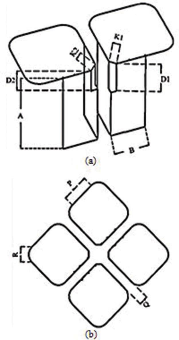
Figure 2: (a) Perspective view of the radiating structures. (b) Top view of the radiating structures.
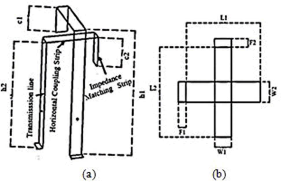
Figure 3: Geometrical description of the feeding section. (a) Perspective view. (b) Top view.
A. Radiating structures
The size of the ground plane considered for this design is 2.5 2.5 m. The radiating structure constitutes the horizontal plates and the vertical plates, as presented in Figure 2. The four radiating structures are placed over the ground plane in the four quadrants, as depicted in Figure 1. As per Figure 1, a pair of vertically oriented rectangular plates shorted to the ground form a shorted patch antenna which constitutes the magnetic dipole. In contrast, the pair of horizontal square plates form the electric dipole. The dimension of resonant dipole or patch antenna is approximately /2. Hence, we started the design with a size of /2 at the center frequency. Later, the dimensions were optimized for a 10 dB impedance bandwidth over the operationalband.
The dimensions of the horizontal and vertical plates determine the lower and upper cutoff frequencies. When the height of the vertical plate (A) is increased, a better impedance match is observed at the lower frequency and the bandwidth is pushed toward the lower frequency. Similarly, increasing the length of the horizontal plates results in the impedance bandwidth being shifted toward the lower frequency. After the parametric investigations, the vertical plates’ heights and lengths are optimally chosen as 515.58 and 273.90 mm. The overall size of the radiating structure is 1040 1040 mm. The two diagonal radiating structures constitute one polarization. Each radiating part consists of two vertically oriented plates connected such as to form a 90 corner. The bottom edges of the plates are connected to the ground plane, and the top edges are connected to the horizontal plate, as shown in Figure 2(a). The width of the two vertically oriented plates, when decreased, increases the impedance bandwidth. The optimized width of the two vertically oriented plates is 244.9 mm. The four radiating structures are positioned in each quadrant with a gap of 90 mm between them, as depicted in Figure 2(b). One corner (inner) of each horizontal plate has a slot to insert the feed, maintaining the physical disconnectivity between the feed and the radiating structures. When the widths w1 and w2 of the slot are increased, the impedance match moves toward the lower cutoff frequency. The other corners of the horizontal plates are curved to improve impedance matching. The dimensions of the radiating structures are tabulated in Table 1.
B. Feeding section
Each pair of diagonally opposite radiating structures is fed with a -shaped feeding section which forms two feeding ports for the entire antenna. The feeding section is physically disconnected from the radiating structures. Each -shaped feeding section has three parts, as shown in Figures 3(a) and (b). The long vertical strip is the transmission line. Its bottom end is 3 mm from the ground plane, connected to the coaxial connector through a small horizontal stub, as shown in the figure. The top end of the transmission line is bent to form the horizontal coupling strip, which is further bent down on the other side, forming a short vertical impedance matching strip. Parametric studies were performed to understand the role of the feed section on the impedance characteristics. A decrease in the transmission line length results in a shift in the lower cutoff frequency, while a decrease in the coupling strip length provides a shift in the upper cutoff frequency. The final optimized dimensions of the feeding sections are tabulated in Table 2.
The transmission line part of the feeding section is placed within one of the radiating structures close to the corner of the vertical plates connected to the edge. The horizontal coupling strip protrudes out of the top horizontal plate through a slot cut at the top corner. The coupling strip enters the other diagonal radiating structure through a triangular slot cut on the top, without physically touching the vertical or the horizontal plates, as shown in Figure 1.
C. Support structures
Mechanical stability is essential to the feeding section and is provided using dielectric support structures made of Teflon (), as shown in Figure 4(a). A dielectric slab, starting from the ground plane, is placed along the width of the transmission line of the feeding section, which is tapered in the top portion. The tapered section is fastened to the feed strip using metallic screws, and the bottom of the slab is attached to the ground with Teflon screws with an additional sidestep, as shown in Figure 4(b). The support structure dimensions are optimally chosen such that the antenna’s performance is not affected, and the same are tabulated in Table 3.
III. OPERATING PRINCIPLE
The pair of vertically oriented rectangular plates shorted to the ground form the magnetic dipole, and the pair of horizontal square plates form the electric dipole. A combined effect of the electric dipole and the magnetic dipole provides a uniform unidirectional radiation pattern [20]. The radiating structures are excited by the fields coupled with the feeding section.
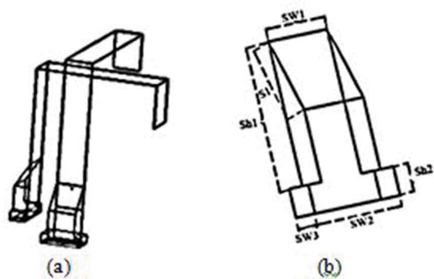
Figure 4: (a) Feed sections with the support structures. (b) Perspective view of support structure.
The significance of the three parts of the feeding section is explained as follows:
The transmission line section and the shorted vertical plates act as an air microstrip line of 50- characteristic impedance, which transmits the electrical signal from the coaxial launcher to the second portion of the feed.
The electrical energy from the transmission line is coupled to the horizontal and vertical plates via the horizontal coupling strip. The length of the coupling strip contributes to the inductive reactance, thereby altering the antenna’s input impedance.
The impedance matching section is an open-circuited transmission line, which can be modeled as a capacitor and contributes to the capacitive reactance. Appropriate choice of its length compensates for the inductive reactance caused by the coupling strip and thereby enhances the impedance bandwidth.
In summary, the operation starts with the excitation of the feeding strips, which couple fields to the corresponding radiating structures and induce currents. The current-induced horizontal radiating plates act as a planar electric dipole, while the shorted vertical radiating structures act as a magnetic dipole, resulting in the overall radiation.
IV. COMPUTATIONAL ASPECTS OF THE DESIGNED ANTENNA
This paper reports a broadband antenna design, and, hence, the solver chosen in the CST simulation tool is the time domain. The accuracy level maintained is 30 dB, and the number of pulses to 50. The mesh type used for the simulation is hexahedral. The mesh cell setting in the tool is an essential parameter the more the mesh cells, the better the accuracy, with the disadvantage of longer computational time. Taking account of these considerations, the cells per wavelength for the maximum cell calculation are optimally set to 15 for the proposed antenna simulation.
The port mode solver supports inhomogeneous port accuracy as we received a warning from the solver indicating that dispersive materials are detected at the ports. Also, the number of pulses is set to 50 as the steady-state criteria are not met with fewer pulses.
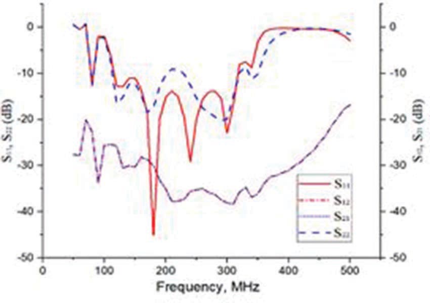
Figure 5: S-parameters of the ME antenna.
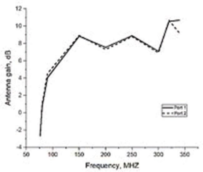
Figure 6: Antenna gain versus frequency plot.
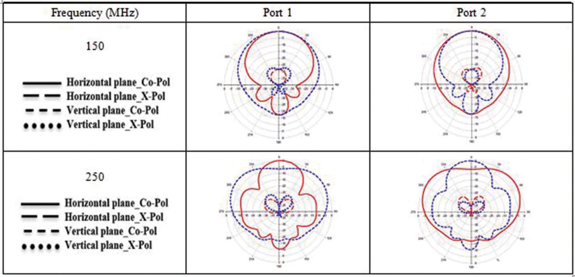
Figure 7: Simulated radiation patterns when ports 1 and 2 excited individually.
Table 1: Dimensions of the radiating structures in mm
| Parameters | P | R | q | K1 | K2 | D1 | D2 | A | B |
|---|---|---|---|---|---|---|---|---|---|
| Values | 273.90 | 141.42 | 92.20 | 56.15 | 66.92 | 198.58 | 146.58 | 515.58 | 244.90 |
Table 2: Dimensions of feeding section in mm
| Parameters | c1 | c2 | h1 | h2 | L1 | L2 | F1 | F2 | w1 | w2 |
|---|---|---|---|---|---|---|---|---|---|---|
| Values | 76.37 | 89.37 | 376 | 319 | 201.85 | 201.85 | 21.51 | 19.88 | 45.36 | 45.36 |
Table 3: Dimensions of the support structure in mm
| Parameters | Sw1 | Sw2 | Sw3 | Sh1 | Sh2 | S1 |
|---|---|---|---|---|---|---|
| Values | 45.36 | 65.36 | 25 | 100 | 20 | 55.90 |
V. RESULTS AND DISCUSSION
The antenna design and simulation are performed using the CST Microwave Studio 2018. The simulated results of the designed antenna are discussed in the following sub-sections.
A. Impedance matching performance
The simulated antenna’s reflection and coupling coefficients with respect to ports 1 and 2 are shown in Figure 5. It is observed that the 10 dB reflection
coefficient with respect to the two ports is over the frequency range of 115340 MHz.
B. Gain and radiation pattern
The antenna gain as a function of frequency is depicted in Figure 6 for both the ports. The maximum gain of the antenna is around 8 dB over the operating band. The 3-dB gain bandwidth is observed over the frequency range of 115340 MHz. The simulated radiation patterns of the proposed antenna are plotted at 150 and 250 MHz in Figure 7. The simulations are performed by exciting each port separately to obtain radiation patterns in each polarization. An extensive simulation-based study is carried out to validate the sensitivity of the proposed antenna to determine the fabrication tolerance of the design parameters. The parameters in the feeding section have a tolerance of 2 mm, and all the remaining dimensions have a tolerance of 5 mm.
VI. CONCLUSION
Simulation-based design of broadband dual-polarized ME antenna element is presented in this paper for very low-frequency astronomical array applications. The antenna designed offers a 10 dB impedance bandwidth over the frequency range of 115340 MHz. The broadside gain of the antenna is about 8 dB, and the isolation between the input ports is about 20 dB over the operating frequency range. It may be noted that the antenna element could not be fabricated, given its size and also the current pandemic situation.
VII. ACKNOWLEDGMENT
The design study reported in this paper was undertaken when the authors participated in SWANtenna20, an antenna design competition organized by the Teaching Learning Centre of the Inter-University Centre for Astronomy and Astrophysics (IUCAA), Pune, India. Based on a detailed assessment by a jury of eminent antenna experts, the team was one of the five to be invited for presentation and interactions with the jury. The authors would like to acknowledge the experts’ valuable inputs, which have gone into preparing this manuscript. They would also like to thank S. Shyam Krishna for proofreading the manuscript.
REFERENCES
[1] S. W. Ellingson., “Antennas in radio telescope systems,” Handbook of Antenna Technologies Springer Singapore, 2015.
[2] K. Sasikumar Raja, C. Kathiravan, R. Ramesh, M. Rajalingam and I. V. Barve, “Design and performance of a low-frequency cross-polarized log-periodic dipole antenna,” The Astrophysical Journal Supplement Series, vol. 27, no. 1,June 2013.
[3] S. Lin, S. Luan, Y. Wang, X. Luo, X. Han, X. Q. Zhang, Y. Tian, and X. Y. Zhang, “A printed log-periodic tree-dipole antenna (Plptda),” Progress In Electromagnetics Research M, vol. 21, pp. 19-32, 2011.
[4] P. S. Kildal, “Radiation characteristics of the EISCAT VHF parabolic cylindrical reflector antenna,” IEEE Transactions on Antennas and Propagation, vol. 32, no. 6, pp. 541-552, June 1984.
[5] P. S. Kildal and E. Sorngard, “Circularly polarized feed for cylindrical parabolic reflector antennas,” EEE Transactions on Antennas and Propagation, vol. 28, no. 2, pp. 210-215,March 1980.
[6] W. Jacob and M. Baars, “The paraboloidal reflector antenna in radio astronomy and communication: theory and practice,” Astrophysics and Space Scienced Library, 2007.
[7] G. Virone, R. Sarkis, C. Craeye, G. Addamo and O. A. Peverini, “Gridded vivaldi antenna feed system for the Northern Cross radio telescope,” IEEE Transactions on Antennas and Propagation, vol. 59, no. 6, pp. 1963-1971, June 2011.
[8] K. Ma, Z. Zhao, J. Wu, S. Mubarak Ellis, and Z. P. Nie, “A printed vivaldi antenna with improved radiation patterns by using two pairs of eye-shaped slots for UWB applications,” Progress In Electromagnetics Research, vol. 148, pp. 63-71, 2014.
[9] C. Lonsdale, R. Cappallo, M. Morales, F. Briggs, L. Benkevitch, , J. Bowman, J. Bunton, S. Burns, B. Corey and L. deSouza, “The Murchison widefield array: design overview,” IEEE Proceedings, vol. 97, no. 8, pp. 1497–1506, Mar. 2009.
[10] K. M. Luk and H. Wong, “A new wideband unidirectional antenna element,” International journal of Microwave and optical technology, vol. 1, pp. 35–44, Apr. 2006.
[11] A. Clavin, “A new antenna feed having equal E-and H-plane patterns,” IRE Transactions on Antennas and Propagation, vol. 2, no. 3 pp. 113–119, Jul. 1954.
[12] P. King, G. Owyang, “The slot antenna with coupled dipoles,” IRE Transactions on Antennas and Propagation, vol. 8, no. 2, pp. 136-143, Mar. 1960.
[13] M. Li, K. M. Luk, “Wideband Magneto-electric Dipole Antennas : Chen Z. (eds) Handbook of Antenna Technologies,” Springer, Singapore, April 2015.
[14] Z. Y. Zhang, G. Fu, S. L. Zuo and S. X. Gong, “Wideband unidirectional patch antenna with -shaped strip feed,” Electronics Letters IET Digital Library, vol. 46, no. 1, pp. 24-26, Jan. 2010.
[15] D. He, Q. Yu, Y. Chen, and S. Yang., “Dual-band shared-aperture base station antenna array with electromagnetic transparent antenna elements,” IEEE Transactions on Antennas and Propagation, vol. 69, no. 9, pp. 5596-5606, Sep.2021.
[16] B. Q. Wu, and K. M. Luk, “A broadband dual-polarized magneto-electric dipole antenna with simple feeds,” IEEE Antennas and Wireless Propagation Letters, vol. 8, pp. 60–63, 2009.
[17] http://www.rri.res.in/SWAN/Strategic_Initiatives.html
[18] R. Maaskant, R. Mittra and A.G. Tijhuis, “Fast solution of multi-scale antenna problems for the square kilometre array (SKA) radio telescope using the characteristic basis function method (CBFM),” Applied Computational Electromagnetics Society Journal, vol. 24, pp. 174, 2009.
[19] National Academies of Sciences, Engineering, and Medicine, “Handbook of frequency allocations and spectrum protection for scientific uses,” The National Academies Press, Second Edition, Washington, DC.
[20] L. Ge, and K. M. Luk., “A wideband magneto-electric dipole antenna,” IEEE Transactions on Antennas and Propagation, vol. 60, no. 11, pp. 4987-4991, Nov. 2012.
BIOGRAPHIES

M. Akila is currently working toward the Ph.D. degree with the Department of Electronics and Communication Engineering, Sri Sivasubramaniya Nadar College of Engineering, Kalavakkam, India.
Her current research interests include metasurfaces for RCS reduction and shared aperture phased array antennas.

Divya N. graduated from Sri Sivasubramaniya Nadar College of Engineering, Kalavakkam, India.
She is currently with Oracle Financial Services Software Limited, Chennai, India.

S. Abishek graduated from Sri Sivasubramaniya Nadar College of Engineering, Kalavakkam, India.
He is currently associated with Johnson Electric Private Limited, Chennai, India.

V. Lingasamy is currently working as a Senior Technical Lead with Sterlite Technologies Limited on LTE/5G radio unit and massive MIMO development.

Hariharan K. graduated from Sri Sivasubramaniya Nadar College of Engineering, Kalavakkam,India.
He is currently with L & T Infotech, Navi Mumbai, India.

Krishnasamy T. Selvan was with SAMEER – Centre for Electromagnetics, Chennai, India, a government of India’s microwave research institution, from 1988 to 2005. From early 2005 to mid-2012, he was with the Department of Electrical & Electronic Engineering, University of Nottingham Malaysia, Semenyih, Malaysia. Since then, he has been a Professor with the Department of Electronics & Communication Engineering, Sri Sivasubramaniya Nadar College of Engineering, Kalavakkam, India.
ACES JOURNAL, Vol. 37, No. 1, 78–84.
doi: 10.13052/2022.ACES.J.370109
© 2021 River Publishers