Compact Cauliflower-Shaped Antenna for Ultra-Wideband Applications
Boumediene Guenad, Abdelhalim Chaabane, Djelloul Aissaoui, Abdelhafid Bouacha, and Tayeb A. Denidni
1Faculté des Technologiques,
Université Hassiba Benbouali de Chlef, N19 Ouled Fares, Chlef, Algeria
b.guenad@univ-chlef.dz
2Laboratoire De Télécommunications,
Université De Tlemcen, BP 230, Pole Chetouane, Tlemcen 13000, Algeria
abdelhafid.bouacha@gmail.com
3Laboratoire des Télécommunications, Département d’Electronique et Télécommunications, Faculté des Sciences et de la Technologie, Université 8 Mai 1945 Guelma, BP 401, Guelma 24000, Algeria
abdelhalim.chaabane@univ-guelma.dz
4Faculté des sciences Technologiques,
Université Ziane-Achour de Djelfa, Djelfa 17000, Algeria
djelloul.aissaoui@univ-djelfa.dz
5Institut National de la Recherche Scientifique
Centre EMT, 800 Rue De La Gauchetière West, Suite 6900, Montreal, Quebec, H5A-1K6, Canada
denidni@emt.inrs.ca
Submitted On: June 27, 2021; Accepted On: December 28, 2021
Abstract
A compact coplanar waveguide (CPW) fed cauliflower-shaped antenna is presented and discussed in this paper. To extend the impedance bandwidth and to improve the impedance matching, fractal geometry having a cauliflower shape is introduced along the edges of the radiator. To validate the simulated results by experimental ones, a prototype of the designed antenna was fabricated on the RO-4350B substrate having a compact size of 0.3623 0.41 0.01524 at 3 GHz. An Agilent 8722ES vector network was used for the reflection coefficient measurement revealing that the –10 dB bandwidth of the fabricated antenna offers an impedance bandwidth of 113% extending from 3.05 to 10.96 GHz. Besides, the antenna’s radiation patterns are measured in an anechoic chamber showing consistent radiation patterns characteristic over the entire working band. Furthermore, the proposed antenna has a peak gain of around 6 dBi and an average radiation efficiency almost over 90% across the entire operating band. Thus, the proposed antenna could be useful in many modern ultra-wideband (UWB) communication systems.
Keywords: Cauliflower-shaped antenna, coplanar waveguide (CPW) fed, hexagonal patch antenna, fractal geometry, ultra-wideband (UWB) antenna.
I. INTRODUCTION
In recent years, telecommunication systems have undergone significant technological change mainly due to the multiplication and growth of newer consumer markets. However, the emergence of the communication markets and the growth of the number of consumers have been accompanied by strict specifications to meet the requirements of the new users. Indeed, the new transmission/reception systems must today provide a maximum of services over different frequency bands and bit rates. The rise of planar technologies (microstrip, coplanar, etc.) for low-power applications is a part of the response to these new requirements. In these contexts, an ultra-wideband (UWB) technology has been purported as a promising solution for the new communication systems. UWB technology has many advantages, including high-speed transmission and low energy profile [1]. Since the definition of the frequency band from 3.1 to 10.6 GHz for UWB communication systems by the FCC in 2002 [2], several antenna structures have been reported by many researchers to enhance the bandwidth of theantennas [4, 5, 6, 7, 8, 9].
However, the design of a UWB antenna presents various challenges to meet the different requirements: low profile, low cost, low radiated power, low power consumption, broadband operability, high data rate transmission, and stable radiation patterns. Various solutions have been proposed to ensure these requirements; the most promising is the introduction of fractal geometries.
The use of these geometries increases the bandwidth and the gain and can introduce the multiband properties without changing the dimensions of the antenna which remains very compact. This allows us to produce miniature broadband antennas with performances similar to those of large antennas. Recently, many fractal structures have been proposed like those proposed in [10, 11, 12, 13, 14, 15, 16, 17, 18]. In [10], an antenna with Koch fractal geometry has been proposed to enhance the bandwidth. However, only 3.3 GHz (3-6.3 GHz) bandwidth has been achieved. A fractal antenna based on an octagonal patch and a semi-elliptical ground plane has been proposed in [11]. Unfortunately, this antenna has low gain which does not exceed 3 dBi and its efficiency is below 90% along the working bandwidth. More recently, in [12], a circular cross-slot AMC has been assembled with a fractal antenna to improve the bandwidth and the gain. The overall impedance bandwidth attained is 129.49% extending from 2.4 to 11.2 GHz. The main disadvantageous of the designed structure are the complexity and the large thickness which is about 9.4 mm. A novel wideband fractal antenna based on a hexagonal-circular geometry with large size of 80.6 80.6 1.6 has been proposed in [13]. The iterations of circular slots inside a hexagonal metallic patch have allowed to achieve a bandwidth of around 2 GHz extending from 1.34 to 3.44 GHz. A compact flexible fractal UWB antenna printed on a 12.5-m flexible polyimide substrate has been presented in [14]. An impedance bandwidth of 15.48 GHz (3.6-19.08 GHz) has been achieved, but it suffers from a low gain which does not exceed 3.5 dBi along the interested frequency band. In [15], a hybrid of Sierpinski and Minkowski geometries has been exploited into a wide antenna for multiband applications. In [16], an antenna with Jerusalem crosses as fractal slots has been introduced to achieve wide bandwidth; no more than 0.6 GHz bandwidth with only 3.5 dBi peak gain and an efficiency value of 70% have been achieved at the resonating frequency. In [17], Minkowski fractal structures are introduced into a flexible antenna for improving the return loss and the impedance bandwidth. This flexible antenna that has been printed into large substrate (97.48 80 0.5 mm) is operating in two narrow bands with bandwidths 0.6 GHz. Carpet geometry has been exploited in [18] for improving the bandwidth of a monopole antenna with defected ground structure. However, only 3.13 GHz bandwidth has beenobtained.
In the present work, a cauliflower-shaped structure is exploited to achieve size-compactness and the UWB response. The fractal geometry was introduced along the edges of the patch and on the outer corners of the truncated ground plane. A prototype was fabricated and measured showing a good concordance between themeasured and the simulated results. The fabricated prototype has an impedance bandwidth of 7.91 GHz extending from 3.05 to 10.96 GHz and stable omni-directional radiation patterns. In addition, the simulated antenna has a reasonable gain (1.39-5.68 dBi) and high radiation efficiency (90%) values over the entire operating frequency band. The designed antenna was calculated and optimized by using the commercial software CST Microwave Studio [19]. The following section will present fractal length generations, describe the proposed antenna geometry, and depict the obtained results.
II. ANTENNA DESCRIPTION AND RESULTS
A. Process of antenna design
The proposed antenna is generated by combining the fractal concept and the hexagonal geometry. The geometrical configuration of this new fractal curve begins with a straight line, called the initiator, which is shown in Figure 1 (iteration 0). The first iteration divides the initial length into four equal parts, and the two centric segments are replaced by three other segments of the same length by forming a regular trapezoid with an angle = 60 as shown in Figure 1 (iteration 1). This iterative process is repeated for the higher-order iteration which is shown in Figure 1 (iteration 2).
Each segment of iteration 1 (generator) is one-fourth the length of the initiator. There are five such segments. Thus, for iteration n, the total length of the curve is (5/4).
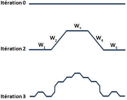
Figure 1: Iteration-wise evolution of cauliflower-shaped structure.
B. Generating fractal geometry using iterative function system (IFS)
An IFS can be used to define the generator. The transformations used to obtain the generator segments are given by the following equations:
| (1) |
| (2) |
| (3) |
| (4) |
| (5) |
The generator is then obtained with the union of these five transformations:
| (6) |
C. Geometry of the proposed cauliflower-shaped antenna
The geometrical structure and the dimensions of the designed antenna are presented in Figure 2. The antenna radiator is constructed by a set of successive assemblies of hexagons that create a cauliflower shape. The antenna structure progress during the design stages is shown in Figure 3. The substrate used for the designed antenna is RO-4350B substrate (relative dielectric constant of 3.48 with the loss tangent of 0.0037 and thickness of 1.524 mm). The overall size of the designed antenna is at 3 GHz as a result of the introduction of a fractal geometry along the edge of the radiating patch and along with the outer corners of the truncated ground plane, an enhanced impedance matching and an extended impedance bandwidth are attained. According to other published works like[1], the resonant frequency f of a comparable antenna with a hexagonal patch can be predicted using eqn (7). In addition, the length of each edge constructing the hexagonal patch can be calculated by eqn (8)
| (7) |

Figure 2: Detailed configuration of the designed CPW cauliflower-shaped antenna.
The equivalent radius r is given by the following formula:
| (8) |
The side length of the hexagonal patch can be calculated using the following formula:
| (9) |
where is the dielectric constant of the substrate, c is the speed of light in free space, h is the thickness of the substrate, q is the side length of the hexagonal radiating patch, r is the radius of a comparable circular patch, and U is the mth zero of the derivative of the Bessel function of order n. The values of U are given as in Table 1.
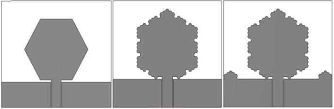
Figure 3: Antenna geometry development during the design steps. (a) Antenna 1. (b) Antenna 2. (c) Antenna 3.
Table 1: Parameters of roots for different modes
| Mode (n, m) | U |
|---|---|
| 0,1 | 0 |
| 1,1 | 1.84118 |
| 2,1 | 3.05424 |
| 0,2 | 3.83171 |
| 3,1 | 4.20119 |
The dimensions of the designed cauliflower-shaped antenna were optimized to attain the desirable performances.
The physical dimensions of the proposed cauliflower-shaped antenna were set as follows: A = 11.5 mm, d = 0.85 mm, g = 0.25 mm, W = 4 mm, W= 18.25 mm, and h = 9.5 mm.
Figure 4 indicates that the working bandwidth is improved by 17.5% and the impedance matching is highly improved at higher frequencies by inserting the cauliflower-shaped structure along the edge of the hexagonal radiating element and on the outer corners of the truncated ground plane. The working bandwidth of the proposed antenna and the initial designs are given in Table 2.
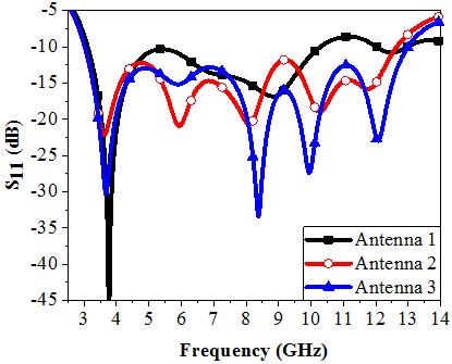
Figure 4: Influence of the fractal structure on the reflection coefficient of the antenna.
Table 2: Antennas working bandwidth comparisons
| Antennas | Working band (GHz) | Bandwidth (GHz) | Bandwidth (%) |
|---|---|---|---|
| Antenna 1 | 3.12-10.30 | 7.18 | 107 |
| Antenna 2 | 3.02-12.64 | 9.62 | 122.86 |
| Antenna 3 | 3.02-12.98 | 9.96 | 124.4 |
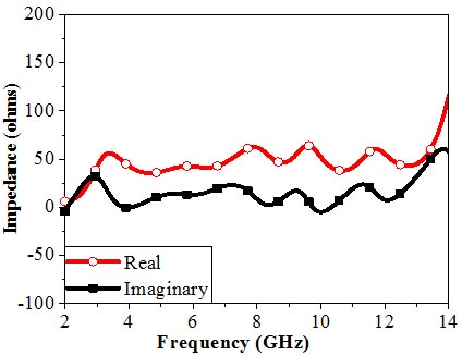
Figure 5: Real and imaginary parts of the impedance.
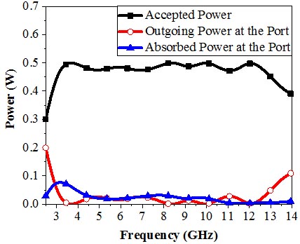
Figure 6: Powers at the input of the antenna.
Figure 5 indicates that the real part of the impedance is nearer, fluctuating around 50 value which is the input impedance of the excitation port. Whereas, the imaginary part is narrowly fluctuating near zero bar during the working bandwidth. Thus, the designed antenna is well adapted throughout the entire working frequency range. At the input of the antenna, the accepted power is compared with the no-transmitted powers and the obtained results are presented in Figure 6. Compared to the level of the accepted power, negligible powers are recorded which prove the well adaptation of the designed antenna. In order to show the utility of the used fractal geometry, the current distribution on the antenna’s surface is presented in Figure 7. At higher frequencies, there is more concentration of the current at the edge of the radiating patch and along the upper edge of the ground plane. The reflections at the edges of the antenna permit creation of other resonant frequencies, which is confirmed by Figure 4. Thus, the fractal geometry has a high contribution to the antenna’s performance improvement by engendering additional resonances and allowing to extend the operationalbandwidth.
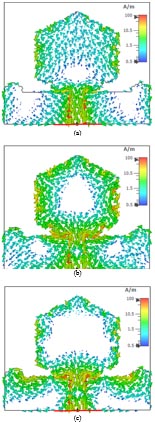
Figure 7: Current distribution at three frequencies. (a) 3.65 GHz. (b) 8.37 GHz. (c) 9.89 GHz.

Figure 8: Fabricated prototype of the proposed UWB CPW cauliflower-shaped antenna.
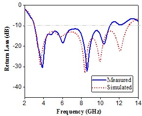
Figure 9: Measured and simulated reflection coefficient of the proposed UWB CPW cauliflower-shaped antenna.
Figure 8 represents a photograph of the fabricated prototype which was printed on the RO-4350B substrate with a total size of 0.3623 at 3 GHz. To confirm the UWB feature of the designed antenna, the reflection coefficient of the fabricated prototype was measured using an Agilent 8722ES vector network analyzer (VNA) with the specifications given in Table 3. High concordance between the simulation and experimental results is detected and the UWB characteristic of the proposed antenna is validated. Figure 9 indicates that the measured reflection coefficient of the fabricated prototype covers a large bandwidth extending from 3.05 to 10.96 GHz (113%), which is wider than the reserved UWB frequency band of 110% (3.110.6 GHz).
Table 3: Specifications of the used VNA
| Parameters | Values |
|---|---|
| Frequency range | 0.0540 GHz |
| IF bandwidth | 10 Hz |
| Maximum input level | 10 dBm |
| Maximum output power | 5 dBm |
| Power resolution | 0.01 dB |
| Output power range | 70 dB (0.0520 GHz) 65 dB (2040 GHz) |
| Output impedance | 50 |
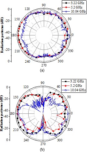
Figure 10: Measured normalized co-polar radiation patterns at three frequencies from the working bandwidth. (a) xz-plane. (b) yz-plane.
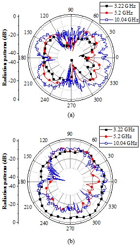
Figure 11: Measured normalized cross-polar radiation patterns at three frequencies from the working bandwidth. (a) xz-plane. (b) yz-plane.
The experimental co-polar and cross-polar radiation patterns of the fabricated prototype were measured in an anechoic chamber by using two-antenna measurement setup. A double ridged horn antenna (model AH-118 working in the range 1-18 GHz) is used for transmitting electromagnetic waves, whereas the fabricated coplanar waveguide (CPW) cauliflower-shaped antenna is used for receiving them.
Table 4: Comparison of the fabricated antenna with other recently published antennas
| Antennas | Substrates | Sizes (mm) | Bandwidths | Ease of fabrication |
| Ref. [26] | FR4 | 100 15 mm () |
2.711.8 GHz (125.52%) | Hard |
| Ref. [27] | FR4 | 49 48.5 0.8 mm (0.49) |
2.910.4 GHz (112.78%) | Easy |
| Ref. [28] | FR4 | 169 169 38.46 mm (1.69) |
3.8–8.8 GHz (79.36%) | Hard |
| Ref. [29] | FR4 | 50 50 1.6 mm (0.5) |
1.5–11 GHz (152%) | Easy |
| Ref. [30] | RO-4003 | 100 104 1.5 mm () |
2–9 GHz (127.27%) | Hard |
| Ref. [31] | FR4 | 100 100 16 mm () |
4.712.4 GHz (90%) | Hard |
| Ref. [32] | FR4 | 45 40 1.6 mm (0.45) |
1.31–6.81 GHz (135%) | Hard |
| Ref. [33] | FR4 | 50 50 11.6 mm (0.5) |
4.39.10 GHz (71.64%) | Easy |
| Ref. [34] | FR4 | 40 40 3.2 mm (0.4) |
5.64–8.63GHz (41.90%) | Easy |
| Ref. [35] | Taconic RF-35 | 120 120 1.6 mm (1.2) |
1.45–4.86 GHz (108.08%) | Easy |
| This work | RO-4350B | 36.23 41 1.524 mm (0.3623) | 3.05–10.96 GHz (113%) | Easy |
The radiation patterns were measured in both the H (xz-plane) and the E (yz-plane) planes at three frequencies from the operating bands 3.22, 5.2, and 10.04 GHz. Figure 10 and 11 indicate that the fabricated prototype has nearly consistent omni-directional radiation characteristics in the H-plane and bidirectionalradiation patterns, like-dumbbell-shaped ones as a conventional monopole, in the E-plane. At higher frequencies, the radiation patterns undergo small distortions due to the reflections along the introduced like-cauliflower-structure and along the upper edge of the ground plane and also due to the excitation of higher-ordermode [22].
The cross-polar radiation patterns in the H-plane retain their star shape over the entire working band with low levels compared to those of co-polar radiation patterns, despite the augmentation of their levels with increasing the frequency, which is due to the excitation of hybrid currents [23].
Figure 12 indicates that the gain and the radiation efficiency simulated by the designed antenna throughout the operating frequency are acceptable and reasonable because their values are better than the values obtained by some recently published works. The gain is varying between 1.39 and 5.68 dBi which isbetter than the one attained in [24]. Whereas, the radiation efficiency is almost over 90% during the working bandwidth which is better than the one achievedin [25].
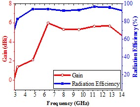
Figure 12: Gain and radiation efficiency achieved by the designed antenna.
In Table 4, the main parameters of the proposed antenna are compared with the ones of some recently published printed antennas. It can be deduced that the parameters of the proposed antenna are better or comparable to those of other antennas. With the above mentioned parameters, it could be deduced that the proposed antenna can be very convenient for many UWB systems.
III. CONCLUSION
In this paper, the utility of the fractal concept is investigated for designing a printed CPW-fed cauliflower-shaped antenna for UWB communication applications and systems. The simulation and measurement results have demonstrated that the working bandwidth and the impedance matching have been improved by inserting fractal geometry along the edge of the radiating patch and on the outer corners of the truncated ground plane. A prototype was fabricated and printed in a compact size of 0.3623 at 3 GHz. The measured results indicated that the cauliflower-shaped fractal antenna is well matched along a large bandwidth extending from 3.05 to 10.96 GHz, which is about 113% enclosing the UWB frequency range. Furthermore, the experimental radiation patterns of the fabricated prototype measured in an anechoic chamber showed stable omni-directional radiation patterns along the operating bandwidth. Besides, reasonable gain (1.395.68 dBi) and high radiation efficiency values (90%) were simulated over the entire operating frequency band. Consequently, the proposed antenna could be useful for many modern UWB communication systems.
ACKNOWLEDGMENT
This work was supported by the Directorate-General for Scientific Research and Technological Development (DG-RSDT) of Algeria.
REFERENCES
[1] M. Kantharia, A. Desai, T. Upadhyaya, R. Patel, P. Mankodi, and M. Kantharia, “High gain flexible cpw fed fractal antenna for Bluetooth/WLAN/WPAN/WiMAX pplications,” Progress In Electromagnetics Research Letters, vol. 79, pp. 87–93, 2018.
[2] D. Aissaoui, N. Boukli-Hacen, and T.A. Denidni, “UWB hexagonal monopole fractal antenna with additional trapezoidal elements,” IEEE Int. Conf. on Ubiquitous Wireless Broadband, ICUWB, pp.1-4, Oct. 2015.
[3] D. Aissaoui, A. Chaabane, A. Boualleg, and M. Guerroui, “Coplanar waveguide-fed UWB slotted antenna with notched-band performance,” Periodica Polytechnica Electrical Engineering and Computer Science., vol. 65, no. 1, pp. 69-73, Jan. 2021.
[4] D. Aissaoui, L. M. Abdelghani, N. Boukli-Hacen, and T. A. Denidni, “CPW-fed UWB hexagonal shaped antenna with additional fractal elements,” Microwave and Optical Technology Letters vol. 58, no. 10, pp. 2370-2374, Jul. 2016.
[5] A. Chaabane and A. Babouri, “Dual-Band Notched UWB MiMo Antenna for Surfaces Penetrating,” Application .Advanced Electromagnetics, vol. 8, no. 3, pp. 6-15, Jun. 2019.
[6] Y. Zehforoosh and M. Naser-Moghadasi, “CPW-fed fractal monopole antenna for UWB communication applications,” Applied Computational Electromagnetic Society (ACES) Journal, vol. 29, no. 2, pp. 748-754, 2014.
[7] M. Guerroui, A. Chaabane, and A. Boualleg, “Super UWB grooved and corrugated antenna for GPR application,” Periodica Polytechnica Electrical Engineering and Computer Science, vol. 66, no. 1, 2022.
[8] A. Chaabane and M. Guerroui “Printed UWB rhombus shaped antenna for GPR applications,” Iranian Journal of Electrical and Electronic Engineering, vol. 73, no. 4, 2021.
[9] X. Bai, J. Zhang, L. Xu, and B. Zhao, “A broadband CPW fractal antenna for RF energy harvesting,” Applied Computational Electromagnetic Society (ACES) Journal, vol. 33, no. 5, pp. 482-487, 2018.
[10] A. Bhattacharya, B. Roy, S. K. Chowdhury, and A. K. Bhattacharjee, “Design and analysis of a Koch Snowflake fractal monopole antenna for wideband communication,” Applied Computational Electromagnetic Society (ACES) Journal, vol. 32, no. 6, Jun. 2017.
[11] G. Geetha, S. K. Palaniswamy, M. G. N. Alsath, M. Kanagasabai, and T. R. Rao, “Compact and flexible monopole antenna for ultra-wideband applications deploying fractal geometry,” Journal of Electrical Engineering and Technology, vol. 13, no. 1, pp. 400-405, 2018.
[12] R.P. Dwivedi, M.Z. Khan, and U.K. Kommuri, “UWB circular cross slot AMC design for radiation improvement of UWB antenna,” International Journal of Electronics and Communications (AEÜ), vol. 117, no. 1, reference: AEUE 153092, 2020.
[13] M. A. Dorostkar, R. Azim, M. T. Islam, and Z. H. Firouzeh, “Wideband hexagonal fractal antenna on epoxy reinforced woven glass material,” Applied Computational Electromagnetic Society (ACES) Journal, vol. 30, pp. 645-652, 2015.
[14] Q. Zou and S. Jiang, “A compact flexible fractal ultra-wideband antenna with band notch characteristic,” Microwave and Optical Technology Letters, vol. 63, no. 3, pp. 1-7, 2020.
[15] N. Sharma, V. Sharma, and S. S. Bhatia, “A novel hybrid fractal antenna for wireless applications,” Progress In Electromagnetics Research M, vol. 73, pp. 25–35, 2018.
[16] S. Heydari, P. Jahangiri, A. S. Arezoomand, and F. B. Zarrabi, “Circular polarization fractal slot by Jerusalem cross slot for wireless applications,” Progress In Electromagnetics Research Letters, vol. 63, pp. 79-84, 2016.
[17] M. Kantharia, A. Desai, T. Upadhyaya, R. Patel, P. Mankodi, and M. Kantharia, “High gain flexible CPW fed fractal antenna for Bluetooth/WLAN/WPAN/WiMAX applications,” Progress In Electromagnetics Research Letters, vol. 79, pp. 87-93, 2018.
[18] A. Bhattacharya, B. Roy, S. K. Chowdhury, and A. K. Bhattacharjee, “A compact fractal monopole antenna with defected ground structure for wideband communication,” Applied Computational Electromagnetic Society (ACES) Express Journal, vol. 1, no. 8, pp. 228-231, Aug. 2016.
[19] CST Microwave Studio, ver. 2019, Computer Simulation Technology, 2019.
[20] D. H Werner and S. Ganguly, “An overview of fractal antenna engineering research,” IEEE Antennas Propagation Magazine, vol. 45, pp. 38-57,2003.
[21] M. Gupta and V. Mathur, “Hexagonal fractal antenna using koch for wireless applications,” Frequenz, vol. 72, pp. 443-453, Aug. 2018.
[22] S. Singhal and A.K. Singh, “Elliptical monopole based super wideband fractal antenna,” Microwave and Optical Technology Letters, vol. 62, no. 3, pp. 1324-1328, Nov. 2020.
[23] A. Chaabane, O. Mahri, D. Aissaoui, and N. Guebgoub, “Multiband stepped antenna for wireless communication applications,” Informacije MIDEM, vol. 50, no. 4, pp. 275-285, Dec. 2021.
[24] M. M. Hosain, S. Kumari, and A. K. Tiwary, “Sunflower shaped fractal filtenna for WLAN and ARN application,” Microwave and Optical Technology Letters, vol. 62, no. 1, pp. 346-354, Aug. 2020.
[25] S. Hota, S. Baudha, B. B. Mangaraj, and M. A. Varun-Yadav, “Novel compact planar antenna for ultra-wideband application,” Journal of Electromagnetic Waves and Applications, vol. 34, no. 1, pp. 116-128, Apr. 2019.
[26] A. Joshi and R. Singhal, “Gain enhancement in probe-fed hexagonal ultra wideband antenna using AMC reflector,” Journal of Electromagnetic Waves and Applications, vol. 33, no. 9, pp. 1185-1196, Mar. 2018.
[27] S. Guruswamy, R. BChinniah, and K. A. Thangavelu, “A printed compact UWB Vivaldi antenna with hemi cylindrical slots and directors for microwave imaging applications,” International Journal of Electronics and Communications (AEÜ), vol. 110, Oct. 2019.
[28] P. R. Prajapati and S. B. Khant, “Gain enhancement of UWB antenna using partially reflective surface,” International Journal of Microwave and Wireless Technologies, vol. 10, no. 7, pp. 835-842, Mar. 2018.
[29] D. M. Elsheakh and E. A. Abdallah, “Ultra-wide-bandwidth (UWB) microstrip monopole antenna using split ring resonator (SRR) structure,” International Journal of Microwave and Wireless Technologies, vol. 10, no. 1, Feb. 2018.
[30] Z. Yang, H. Jingjianti, and Y. Naichang, “An antipodal Vivaldi antenna with band-notched characteristics for ultra-wideband applications,” International Journal of Electronics and Communications (AEÜ), vol. 76, pp. 152-157, Jun. 2017.
[31] D. Sankaranarayanan, D. Venkatakir and B. Mukherjee, “A novel compact fractal ring based cylindrical dielectric resonator antenna for ultra wideband application,” Prog. in Electromagnetics Res. vol. 67, pp. 71-83, Sep. 2016.
[32] A. Kumar, S. Dwari, G. P. Pandey, and B. K. Kanaujia, “A high gain wideband circularly polarized microstrip antenna,” International Journal of Microwave and Wireless Technologies, vol. 74, pp. 125-130, Jun. 2018.
[33] A. Desai, T. K. Upadhyaya, R. H. Masotti, and P. Mankodi, “Wideband high gain fractal antenna for wireless applications,” Progress In Electromagnetics Research, vol. 12, no. 7, pp. 678-687,Mar. 2019.
[34] R. Anand and P. Chawla, “Optimization of inscribed hexagonal fractal slotted microstrip antenna using modified lightning attachment procedure optimization,” Microwave and Wireless Technologies, vol. 12, no. 6, pp. 519-530, Mar. 2020.
[35] G. Liu, J. Gu, Z. Gao, and M. Xu, “Wideband printed slot antenna using Koch fractal metasurface structure,” International Journal of RF and Microwave Computer‐Aided Engineering, vol. 30, no. 3, Nov. 2020.
BIOGRAPHIES

Boumediene Guenad received the magister degree in signals and systems and the Ph.D. degree in telecommunications science from the University of Tlemcen, Tlemcen, Algeria, in 2005 and 2013, respectively.
He is currently working as an Assistant Professor with the Department of Electronic Engineering, Faculty of Technology, University of Chlef, Ouled Farès, Algeria, and a Researcher Member of the Telecommunications Laboratory of Tlemcen (LTT), Tlemcen, Algeria. His current research areas of interest include multi-beam antenna arrays, fractal antennas, ultra-wideband antennas, and meta materialantennas.

Abdelhalim Chaabane received the Ph.D. degree and completed his habilitation in electronics in 2017 and 2020,respectively.
He is currently working as an Associate Professor with the Université 8 Mai 1945 Guelma, Algeria. He is a member of Telecommunications Laboratory, Université 8 Mai 1945 Guelma. His current research areas of interest include fractal antennas, ultra-wideband antennas, meta material antennas, and ground-penetrating radar antennas.

Djelloul Aissaoui received the magister degree in signals and systems and the Ph.D. degree in telecommunications science from the University of Tlemcen, Tlemcen, Algeria, in 2007 and 2019, respectively.
He is currently working as an Assistant Professor with the Department of Electrical Engineering, Faculty of Science and Technology, University of Djelfa, Djelfa, Algeria. His current research areas of interest include fractal antennas, ultra-wideband antennas, and meta material antennas.

Abdelhafid Bouacha received the magister degree in signals and systems and the Ph.D. degree in telecommunications science from the University of Tlemcen, Tlemcen, Algeria, in 2005 and 2012,respectively.
He is currently an Assistant Professor with the Telecommunications Department, Faculty of Technology, University of Tlemcen and a Research Member of the Telecommunications Laboratory of Tlemcen (LTT). His current research activities are focused on advanced antenna systems for 5G network and beyond.

Tayeb A. Denidni received the M.Sc. and Ph.D. degrees in electrical engineering from Laval University, Quebec City, QC, Canada, in 1990 and 1994, respectively.
From 1994 to 2000, he was a Professor with the Engineering Department, Université du Quebec in Rimouski (UQAR), Rimouski, QC, Canada, where he founded the Telecommunications Laboratory. Since August 2000, he has been with the Institut National de la Recherche Scientifique (INRS), Université du Quebec, Montreal, QC, Canada. His current research areas of interest include reconfigurable antennas using EBG and FSS structures, dielectric resonator antennas, meta material antennas, adaptive arrays, switched multi-beam antenna arrays, ultra-wideband antennas, microwave and development for wireless communications systems.
ACES JOURNAL, Vol. 37, No. 1, 68–77.
doi: 10.13052/2022.ACES.J.370108
© 2021 River Publishers