Isolation Enhancement using CSRR Slot in the Ground for Compact Two-Element Textile MIMO Antenna
Navneet Sharma, Anubhav Kumar, Asok De, and R. K. Jain
1Department of Electronics and Communication Engineering
Shobhit Institute of Engineering & Technology (Deemed to be University), Meerut (U.P.) 250110, India
navneet1979@gmail.com, rajput.anubhav@gmail.com, rakesh.jain@shobhituniversity.ac.in
2Delhi Technological University, Delhi 110042, India
asok.de@gmail.com
Submitted On: January 28, 2022; Accepted On: June 14, 2022
Abstract
A textile integrated, two-element, multiple-input multiple-output (MIMO) antenna is designed for Wi-Fi, wireless local area network (WLAN), and wearable biomedical applications. A CSRR slot and horn-shaped decoupling structure increases impedance matching and reduces the current movement from one element of antenna to another element which increases the isolation to 7.4 dB. The CSRR slot in the ground is accomplished between the elements to mitigate the surface current and enhance the isolation up to 27.4 dB. The 10-dB radiation exists from 4.65 to 5.97 GHz with more than 20-dB isolation in the full operating band where the maximum isolation is found to be 49.45 dB at 4.7 GHz. MIMO parameters are investigated in a two-element antenna, in which acceptable results are obtained. Bending analysis and phantom analysis are performed for wearable applications which demonstrate the acceptable results.
Index Terms: Defected ground structure (DGS), flexible antenna, isolation enhancement, MIMO antenna, textile antenna.
I. INTRODUCTION
There has been an extreme influence of body worn antennas for communication system recently. To satisfy the demands of communication in today’s scenario, the antenna has to be robust, flexible, cost effective, compact, and reliable for wearable applications [1]. Flexible and textile antenna could be easily incorporated in the wearable and portable devices, but accomplishing the antenna in the compact space is a challenging task for a researcher. Among several technologies of antenna design, the use of multiple-input multiple-output (MIMO) antenna is a popular choice because in MIMO, same data is sent as multiple signals simultaneously through multiple antennas. This results in high data rate, diversity performance, high channel bandwidth, link reliability, high channel capacity, multiple transmission and reception capability, as well as spatial multiplexing [2, 3]. When multiple antennas are incorporated in small space, the distance between antennas is minimized due to which the mutual coupling increases and affects the MIMO parameters. High isolation between antenna elements could primarily be achieved in MIMO antennas by positioning the radiators at high distance ( /2) from each other so that mutual coupling is neutralized. This results in a large sized antenna that is not suitable for wearable applications. Other methods to escape mutual coupling is to place the radiator either perpendicularly [3] or at orthogonal positions [4, 5]. Extended ground structure [6] or a conductive line between the radiators [7] also considerably reduces the size of antenna by bringing the radiators closer. To further reduce the size, which is compatible to the requirements of wearable devices, several decoupling structures such as meander lines, slots, stubs, as well as metamaterial structures such as EBG and SRR are utilized. Meander line structures are easy to implement on rigid FR-4 substrate [8] and provide good isolation, but antennas have to compromise with flexibility. Meander lines are also implemented on flexible jeans substrate to enhance isolation [2], but this approach increases design and fabrication complexities. Alternatively, T-shaped [9–12] and E-shaped [13] stubs, vertical and horizontal slotted ground [14], funnel-shaped defected ground structure [15], neutralized line between the radiators along with defected partial ground [16], decoupling stubs [17], and combination of vertical and horizontal ground for enhanced isolation [14] are very common, easy to implement, and simpler approach on jeans substrate. Researchers had also utilized dielectric resonators along with annular rings [18] to curb mutual coupling. In [19], four-element CPW-fed MIMO antenna is proposed for UWB applications with CSRR notch, where distance between antenna and parasitic stub is used to improve the isolation. Researchers have also used metamaterial structures such as H-shaped EBG [20] for isolation enhancement. Orthogonalfeed with stubs [4], defected ground structures, and square patch with chamfered feed [21] are some of the hybrid structures deliberately utilized for improved isolation and reducing size of antenna.
An antenna with flexible textile substrate has the following advantages over their fixed counterparts.
The antenna can be designed conformal, enabling it to fit to the design of the device. Flexible textile antennas are also shock resistant, especially applicable on fast moving devices or wearables such as shoes or wrist watch.
Fabric antennas are environment friendly when disposed and are immune to high temperature deformations that may exist in antennas with fixed substrates.
There are several types of textile materials that are used as a substrate to design flexible antennas [22] where jeans material, popularly known as denim material, is an obvious choice for research on wearable antennas because of its rugged and long lasting quality [23], low cost, and time saving fabrication techniques [1]. The fabric is highly researched and the textile characteristics are rigorously studied [24] and dielectric constant is determined [25].
The proposed textile antenna could be used in wearable applications with the following novelty and technical contributions.
The proposed antenna design is modest as compared to other structures [2, 9, 16] and is integrated on most popular, rugged, flexible, easily available, and inexpensive jeans textile material.
The suggested decoupling structure in this work enhances the port to port isolation significantly up to 49.45 dB which is expressively higher than the other related works [2, 4, 13, 15, 17].
The antenna is analyzed on different curvatures and maintains its band for wireless local area network (WLAN), Wi-Fi, and 5.8 GHz (ISM) with minimal effect on impedance matching as well as isolation.
To analyze the on-body radiation effect of antenna, specific absorption rate (SAR) is obtained using four layered phantom model. The obtained SAR is 0.2680 W/Kg which is lower than other reported work [2, 13, 16].
The antenna is designed with required Wi-Fi, WLAN, and ISM band applications and fulfilled the compact and flexible requirement for wearable applications. The demonstration of human body effect on the antenna is discussed in the manuscript where antenna is designed with traditional equations, explained in eqn (1)–(3), and CSRR mitigates the current which is explained in Figure 1 (f). The low envelope correlation coefficient (ECC) and high isolation ensures that the antenna can be used for wireless communication applications.
II. MIMO ANTENNA DESIGN AND EVOLUTION STEPS
The optimized, compact two-element MIMO antenna is fabricated on lossy [24, 26] jeans material of 1 mm thickness (dielectric constant,) [2, 6, bib15--bib17, 24] which is illustrated in Figure 1 (a) with a prototype in hardware as shown in Figure 1 (b). The edge-to-edge dimensions of the antenna are 28 mm (Wb) 24 mm (Wh). Primarily, we have to design a single element antenna and calculate the length () and the width of the feed with help of eqn (1)–(3) [27]. In MIMO antenna design, two elements are incorporated with the conventional edge-to-edge distance.
where width of the patch, and height of the substrate where dielectric constant ( for jeans (denim) material is 1.7.
The effective dielectric constant is given by
| (1) |
| (2) |
where resonant frequency.
The characteristic impedance can be given by
| (3) |
For MIMO antenna, the two elements are placed minimum at the distance of /4 for considerable isolation. However, this distance could be reduced by using isolation structures such as SRR and EBG. The calculated feed is W1 = W2 = 2.7 mm (width) and W3 = W4 = 13.6 mm (height) with .
Other dimensions of two-element MIMO antenna in mm are: W5 = 3.9, W6 = 23, W7 = 8.5, W8 = 8, W9 = 8.9, r1 = 6.7, r2 = 6.6, W10 = 1.5, and W11 = 1.5. The simulation of flexible and textile MIMO antenna is performed on Ansys HFSS-19 simulation software.

Figure 1: (a) Proposed MIMO antenna (dimensions). (b) Prototype (fabricated). (c) Steps (evolution). (d) |S| parameters (steps) in dB. (e) |S| parameters (steps) in dB. (f) Surface current distribution at 5.8 GHz.
The two-element MIMO is evolved in four major iterations/steps, as is demonstrated in Figure 1 (c). In step-1, the ground height is 3.9 mm with 13.6-mm microstrip feed height where feed width of 2.7 mm is used to achieve approximately 50- impedance matching. The |S| in dB exists from 4.75 to 5.69 GHz, whereas the averaged isolation is at 10 dB with highest isolation of 13.66 dB as revealed in Figures 1 (d) and (e), respectively. In step-2, while increasing the ground vertically between two elements, isolation increases |S| because this modification perturbs the current movement toward the modified ground structure from port one [6]. The |S| in dB ranges from 4.80 to 5.87 GHz, whereas isolation is improved at this stage and ranges close to 17 dB, as is evident from Figures 1 (d) and (e). In step-3, a horn-shaped structure is implemented in the ground, which curates the impedance matching of antenna and increases the |S| that varies from 4.53 to 5.96 GHz. The horn-shaped decoupling structure reduces the surface current between antenna elements and improves the isolation by 7 dB. In the last step, CSRR slot is accomplished in the decoupling structure, thereby mitigating the surface current and improving the isolation up to 27 dB. The |S| characteristics are further improved, which varies from 4.65 to 5.97 GHz with enhancement in isolation. The isolation at this stage has reached a peak of 49.45 dB, which is an improvement of 123.09% as compared to step-3 (without CSRR). Surface current analysis of two-port antenna is analyzed at 5.8 GHz which clearly demonstrates that the CSRR effectively diminishes the surface current and improves the isolation as shown in Figure 1 (f).
III. BENDING ANALYSIS OF ANTENNA
To study the performance of two-port antenna with structural deformations, the antenna is deliberately bent on a polystyrene base cylinder with diameter of 25, 20, 15, and 10 cm using the wrapping tool in HFSS 19 [28]. The cylinder is then removed and simulation is performed. The screenshots are shown in Figure 2 (a), whereas Figure 2 (b) depicts the placement of designed antenna on polystyrene base. The |S| and |S| characteristics in dB (simulated) are shown in Figures 2 (c) and (d). Figure 2 (f) shows the variation in radiation efficiency, where small variations are observed. The size of antenna is reducing and impedance matching varies when bending process is applied on two-port antenna; therefore, |S| and |S| are shifted toward higher frequency, where small variation is found [36]. The minimum variation is found in gain of antenna in bending process is due to small variations in efficiency as depicted in Figure 2 (e). The bending analysis proves that the proposed antenna is working effectively, without compromising with the radiating bandwidth and isolation.

Figure 2: Bending of antenna at 10, 15, 20, and 25 cm diameter (simulated). (b) Bending of antenna at 10, 15, 20, and 25 mm diameter (measured). (c) |S| in dB for bending analysis (simulated and measured). (d) |S| in dB for bending analysis (simulated and measured). (e) Peak realized gain variations on bending. (f) Radiation efficiency variations on bending.
IV. PHANTOM ANALYSIS
The wearable antennas are used near the human tissues; therefore, certain parameters of radiation have to be studied for wearable applications. The effect of radiation on different layers of human skin is measured in terms of SAR.
Absorption of electromagnetic (EM) energy when exposed to radiation of antenna is calculated in SAR. In other words, it is the radiated power absorbed by human tissue of 1 Kg, averaged at 1 or 10 g, as illustrated in eqn (4)
| (4) |
where is electrical field in volts/meter, = volume in meter cube, = position of vector, is sample density, and is the conductivity in Siemens/meter.
As per internationally approved standards, the value of SAR has to be under 1.6 W/Kg for safe use of antenna near human body [29]. An analysis of the antenna positioned at 20-mm distance from a phantom model is performed. The phantom model (four layered) is composed of skin layer (2-mm thick), fat layer (3.5-mm thick), muscular layer (10-mm thick), and bone (10-mm thick) as depicted in Figure 3 (a). The tissue characteristics such as conductivity, loss tangent, and relative permittivity at 5.8-GHz frequency are given in Table 1. The |S| and |S| parameters of antenna in dB without phantom and with phantom are shown in Figures 3 (c) and (d). The minimum variations are observed in s-parameters when the four-layered phantom model is positioned at 20 mm from antenna, and this could be a feasible distance for wearable applications. The maximum SAR value was evaluated as 0.2680 W/Kg when averaged on 10 g of phantom model, when excited with a source power of 10 mW as is relevant from Figure 3 (b). The radiation efficiency and realized gain, in the absence and presence of phantom model, are depicted in Figures 3 (e) and (f), and a small variation in gain is found as a result of grating lobe reflection from the phantommodel.
Table 1: Characteristic values of human body tissues (5.8 GHz) [31]
| Tissue | Conductivity (S/m) | Relative permittivity () | Loss tangent () |
|---|---|---|---|
| Skin | 3.717 | 35.114 | 0.32807 |
| Muscles | 4.9616 | 48.485 | 0.31715 |
| Fat | 0.29313 | 4.9549 | 0.18335 |
| Breast fat | 0.41974 | 4.4976 | 0.28924 |
| Bone | 1.1544 | 9.6744 | 0.36981 |
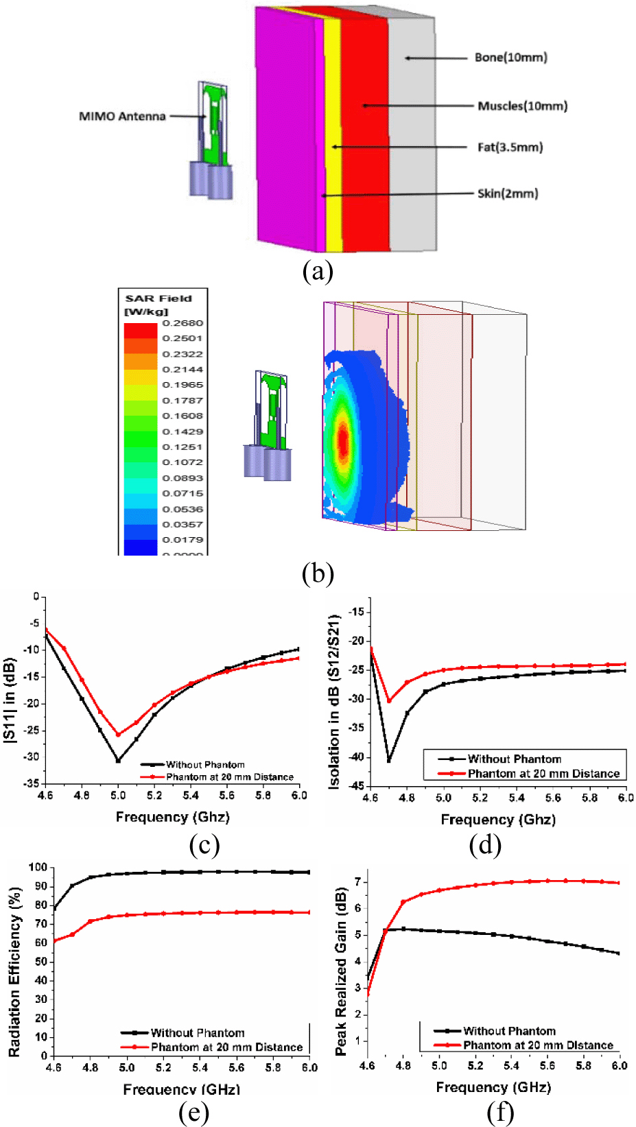
Figure 3: Antenna positioned on phantom [30]. (b) Analysis of SAR (phantom). (c) |S| in dB on phantom. (d) |S| on phantom. (e) Radiation efficiency on phantom. (f) Peak realized gain on phantom.
V. RESULTS AND DISCUSSIONS
The measurements were executed using VNA (Anritsu MS 2025B). The simulated and measured results of |S| and |S| in dB are depicted in Figures 4 (a) and (b), where |S| in dB extends from 4.7 to 5.9 GHz with more than 20-dB isolation and minimum variation is found in the measured results. The anechoic chamber measurement for gain, where the amplitude of the transmitted signal ( from MIMO is measured on the received signal by horn antenna at a distance of 3 m. The gain is determined using formulae as given in eqn (5).
| (5) |
where and are antenna gains of the MIMO antenna and horn antenna, respectively, and is the distance between the two antennas and is the measured wavelength. The realized gain variesfrom 3.37 to 5.23dB and less than 0.5 dB variation is observed with measured results due to environment losses associated with high frequency as depicted in Figure 4 (b). Radiation efficiency (simulated) is higher than 90% as is given in Figure 4 (c). The two-port antenna is measured on different body positions such as wrist, thigh, chest, and biceps for “on-body” wearable analysis as depicted in Figure 4 (f). The measured |S| and |S| in dB are depicted in Figures 4 (h) and (i). The results show that the antenna is performing satisfactorily when placed on any body part and also the antenna is able to maintain its isolation at less than 20 dB. Further, the antenna is placed on cap, shoes, bag, and riding helmet for portable wearable analysis as depicted in Figure 4 (g), where the antenna has minimum variations in s-parameters due to coupling effect, but the experimental results show acceptable performance in terms of |S| and |S| in dB as shown in Figures 4 (j) and (k). The measurement of radiation pattern is performed in anechoic chamber and the normalized patterns in x-z and y-z planes at 5.8 GHz frequency are shown in Figure 4 (e) and during measurement port 2 is terminated with 50- terminator and port 1 is excited. The difference between co- and cross-plane is observed at more than 20 dB in end-fire direction and stable radiations areobserved. Figure 4 (d) represents the simulated and measured VSWR.
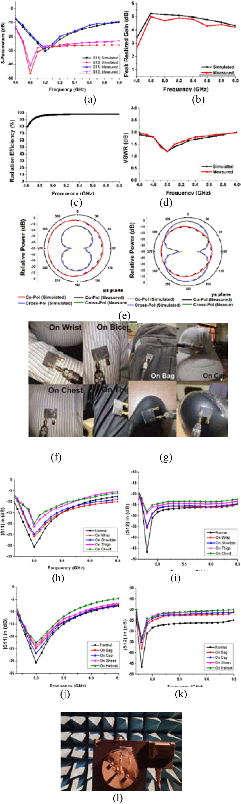
Figure 4: Results (measured and simulated). (a) S-parameters (measured and simulated). (b) Realized gain (dB) (measured and simulated). (c) Radiation efficiency. (d) Simulated and measured VSWR. (e) Normalized radiation patterns in yz and xz planes at 5.8 GHz (measured and simulated). (f) Antenna placed on various body parts. (g) Antenna placed on different objects (h). |S| characteristics in dB on different body parts. (i) |S| characteristics on different body parts. (j) |S| in dB on different objects. (k) |S| in dB on different objects. (l) Measurement of antenna in anechoic chamber.
VI. ANALYSIS OF ECC, CCL, TARC,AND DG
A Formulation
For evaluating MIMO performance in diversity environment, certain parameters such as channel capacity loss (CCL), diversity gain (DG), total active reflection coefficient (TARC), and ECC are taken into consideration. All the parameters are measured using the eqn (6)–(9) [4]
| (6) |
| (7) |
| (8) |
where phase angle between adjacent/diagonal ports.
| (9) |
and = correlation matrix at the receiving end.
B Explanation
ECC is an important parameter that represents the correlation between the antenna elements. ECC ranges from 0 to 1 where 0 represents no correlation and antennas are completely decoupled, whereas 1 indicates identical pattern and high coupling between antennas. A truly uncorrelated channel is highly unlikely; therefore, ECC, which is close to 0, is desirable, thereby exhibiting high diversity performance and DG [19]. ECC and DG are calculated from s-parameters and are extracted from eqn (6) and (7). The measured and simulated DG and ECC are illustrated in Figures 5 (b) and (a), in which ECC is less than 0.005 and DG is near 10 dB.
Radiating efficiency and bandwidth of MIMO are not accurately characterized by scattering matrix; therefore, TARC is used [20]. Two element antenna scattering parameters are used to extract the TARC from eqn (8). TARC with = 0, 30, 60, 90, 120, 150, and 180 is given in Figure 5 (c), where minimum variations are observed.
CCL is a measure of throughput of antenna, where the CCL value should practically be less than 0.4 bit/s/Hz [11]. For the whole operating band, which represents high throughput. The CCL is measured through eqn (9). The measured and simulated CCL is depicted in Figure 5 (d) and is lower than 0.4 bits/s/Hz.
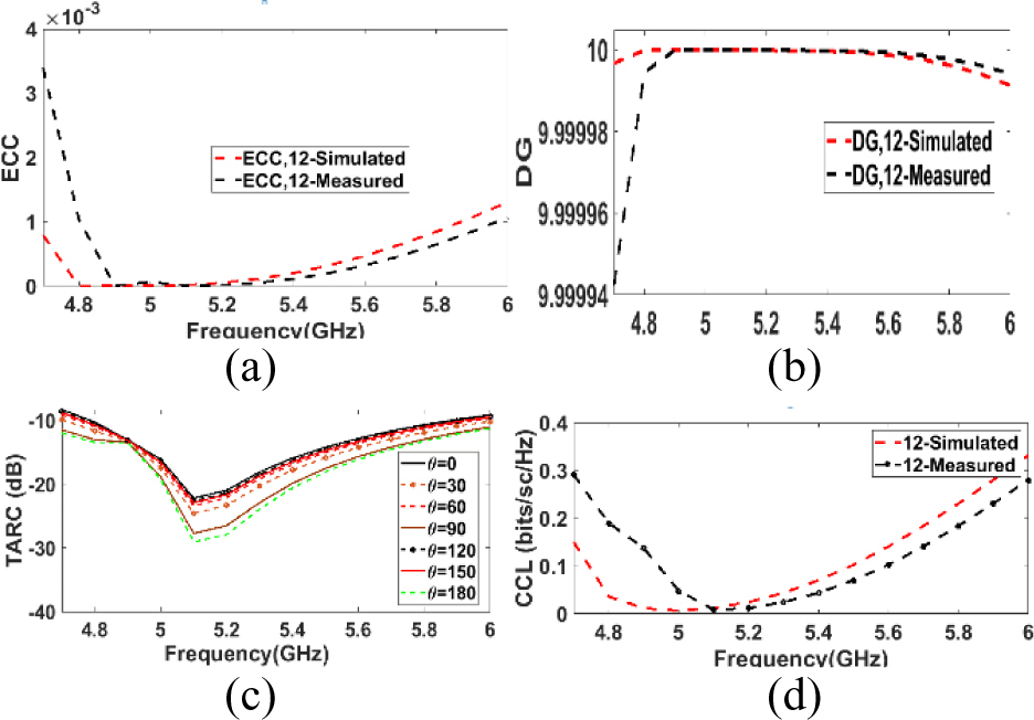
Figure 5: MIMO parameters. (a) ECC. (b) Diversity gain. (c) TARC. (d) CCL.
VII. TUMOR ANALYSIS ON FEMALE BREAST PHANTOM MODEL
Tumor in the female breast is very common in the soft glandular tissue, which is more vulnerable to developing malignant cells. In this paper, tumor analysis is investigated on female breast phantom model, with respect to SAR analysis.
The characteristics of tissue such as permittivity and permeability vary on occurrence of malignant (tumor) cell, thereby changing the SAR characteristics of the cell [32, 33]. Therefore, SAR analysis is the direct method for prediction of tumorous cells. A three-dimensional breast model (female) is illustrated in Figure 6 (a) for SAR analysis. The distance between breast model and antenna is 15 mm. The breast model with tumor size of 8 mm radius is composed of glandular tissue (r = 40 mm), breast fat (r = 55 mm), and outermost skin layer (r = 60 mm). The respective thickness of the layers is 40, 15, and 5 mm of glandular, breast fat, and skin layers [30, 32].
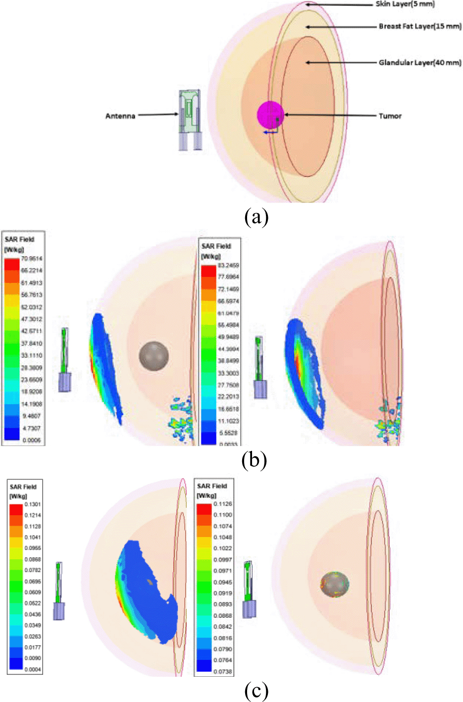
Figure 6: (a) Breast model. (b) SAR of skin (without and with tumor. (c) SAR of glandular cell (with tumor) and SAR of tumor.
A Detection of tumor
As the microwave field penetrates the tissue, the power is subsequently rejected through reflections and dissipation. Several tumor detection techniques are conventionally accounted [34, 35]. In the proposed method, tumor detection could be accomplished by using two different hypotheses. In the first hypothesis, the SAR value of the tumor and glandular tissue in the vicinity is analyzed for the detection of tumor cell; here, it is observed that the higher SAR value of the glandular tissue with tumor varies from 0.1301 to 0.0004 W/Kg, whereas SAR value of tumor tissue in glandular cell varies from 0.1126 to 0.0738 W/Kg, as shown in Figure 6 (c). The SAR difference denotes the presence of tumor, where the huge difference of minimum SAR value is detected in tumor cell and its neighboring glandular cell. In the second hypothesis, the difference in average SAR proves the presence of malignant (tumor) cell. It is observed that SAR values are decreased with the presence of tumor as given in Figure 6 (b). SAR difference (with and without tumor) is depicted in Table 2. In this investigation, the tumor analysis is observed effectively, which can be valuable for cancer detection and biomedical applications. In Table 3, the proposed two-port textile MIMO antenna is compared to the existing MIMO antenna, where proposed antenna is flexible and compact, based on textile material, with high isolation and have acceptable MIMO parameters, which can be applicable for WLAN and Wi-Fi communication in wearable applications.
Table 2: SAR analysis (with and without tumor)
| SAR (W/Kg) analysis at 5.8 GHz | ||||
| Tissue | With tumor |
Without tumor | SAR diff. | |
| Skin | Max | 70.951 | 83.2459 | 12.2945 |
| Min | 0.0006 | 0.0033 | 0.0027 | |
| Breast fat | Max | 2.6118 | 2.6283 | 0.0165 |
| Min | 0.0004 | 0.0003 | 0.0001 | |
| Glandular cell | Max | 0.1301 | 0.1240 | 0.0061 |
| Min | 0.0004 | 0.0003 | 0.0001 | |
| Tumor cell | Max | 0.1126 | – | – |
| Min | 0.0738 | – | – |
Table 3: Proposed MIMO antenna compared with existing MIMO antenna
| Ref | Size (mm) | 10 dB (GHz) | Isolation (dB) | Gain (dB) | Substrate | Flexibility | Isolation technology used | ECC |
| [2] | 60 97 | 1.5–3.8, 4.1–6.1 | 15, 20 | 4 | Jeans | Yes | Meander line structures | 0.1 |
| [4] | 31 31 | 3.3–4.3 | 24 | 3.45 | Jeans | Yes | Stubs and DGS, and orthogonal feed | 0.2 |
| [7] | 140 70 | 2.33–2.5 | 26 | 4.7 | Shieldit Textile | Yes | Conductive line | 0.01 |
| [9] | 76 37 | 2.00–6.23 | 29.26 | 2.88 | Felt | Yes | T-shaped stubs, ring-shaped slots, and meander line | 0.01 |
| [11] | 80 170 | 3.4–3.6 and 3.9–4.5 | 20 | 6.8 | FR4 | No | T-shaped decoupling structure | 0.3 |
| [12] | 18 44 | 3.3–3.65 and 4.8–5.5 | 18 | 5.93 | FR4 | No | Inverted T-shaped slot | 0.002 |
| [13] | 55 35 | 2.4–9.0 | 18 | 9 | Jeans | Yes | E-shaped stubs | 0.06 |
| [14] | 71.7 50 | 3.24–3.05 | 19 | 4.7 | FR4 | No | Vertical and horizontal slotted ground | 0.0035 |
| [15] | 35 30 | 3.11–5.15, 4.81–7.39 | 19, 21 | NA | Jeans | Yes | Funnel-shaped DGS | 0.18 |
| [16] | 30 50 | 3.14–9.73 | 32 | 2.7 | Jeans | Yes | Neutralized ground | 0.12 |
| [17] | 70 40 | 1.83–8 | 22 | 4 | Jeans | Yes | I-shaped stubs | 0.01 |
| [21] | 93 93 | 2.16–2.75 | 15 | 4.02 | FR4 | No | Square patch with circular chamfered corners | 0.03 |
| Proposed | 24 28 | 4.65–5.97 | 20 | 4.57 | Jeans | Yes | Horn-shaped defected coupling structure with CSRR | 0.005 |
VIII. CONCLUSION
A two-element MIMO antenna is designed and fabricated on denim textile as a substrate for 5G, WLAN frequency bands: Wi-Fi/WLAN (HIPERLAN, U-NII) (IEEE 802.11 a/h/j) working group as well as biomedical (ISM) band at 5.8 GHz. The isolation is achieved from defected ground decoupling structure such as horn-shape and CSRR. The horn-shaped ground disturbs the surface current and improves the isolation up to 5 dB, whereas CSRR-shaped slot effectively diminishes the surface current and improves the isolation up to 27 dB. Overall, 20-dB isolation is achieved on the 10-dB impedance bandwidth of the proposed antenna that exists from 4.65 to 5.97 GHz; the antenna has simple decoupling structure and flexible substrate. The two-port MIMO antenna parameters are under the acceptable limit and antennas have minimum effect in s-parameter when analysis on bending was performed; this shows that the antenna is a suitable choice for wearable applications. Wi-Fi antennas are updated with MIMO technologies that allow group of devices to connect simultaneously to create efficient network and enhance speed and coverage. The MIMO antennas that are compact and integrated on fabrics could invariably be used for such applications in near future. The future technology holds easy-to-use and easy-to-fabricate antennas on other wearable textile substrates for 5G and 6G technologies that would be used in future. In future, more than two antenna elements would be designed for Internet of Things (IoT), sports, entertainment, and wearable technologies.
REFERENCES
[1] C. L. G. Monti and L. Tarricone, “Wearable antennas: Nontextile versus fully textile solutions,” IEEE Antennas and Propagation Magazine, vol. 61, no. 2, pp. 71-83, 2019.
[2] R. Sourav, G. Soumendu, S. P. Soumya, and C. Ujjal, et al., “Dual-polarized textile-based two/four element MIMO antenna with improved isolation for dual wideband application,” International Journal of RF and Microwave Computer-Aided Engineering, vol. 30, no. 9, pp. e22292, 2020.
[3] A. A. Ibrahim, J. Machac, and R. M. Shubair, “UWB MIMO antenna for high speed wireless applications,” The Applied Computational Electromagnetics Society (ACES) Journal, pp. 1294-1299, 2019.
[4] K. A. Asok De and R. K. Jain, “Circular polarized two-element textile antenna with high isolation and polarization diversity for wearable applications,” International Journal of Microwave and Wireless Technologies, pp. 1-9, 2022.
[5] D. Chengzhu, Y. Zhipeng, J. Gaoya, and Z. Shunshi, et al., “Design of a co-planar waveguide-fed flexible ultra-wideband-multiple-input multiple-output antenna with dual band-notched characteristics for wireless body area network,” International Journal of RF and Microwave Computer-Aided Engineering, vol. 32, no. 3, pp. e22997, 2022.
[6] J. Pankaj, K. Anubhav, D. Asok, and K. J. Rakesh, et al., “Flexible and textile two-port compact antenna for WLAN and wearable applications,” 2021 8th International Conference on Signal Processing and Integrated Networks (SPIN). IEEE, pp. 308-311, 2021.
[7] A. Ismahayati, R. K. Muhammad, H. R. Ali, H. Norshakila, A. R. Hasliza, A. W. M. Wan Zuki, I. M. Arif, J. Muzammil, and M. Y. Mohd Najib, et al., “Investigation on wearable antenna under different bending conditions for wireless body area network (WBAN) applications,” International Journal of Antennas and Propagation, vol. 2021, pp. 9, 2021.
[8] D. J. Deng, J. Li, L. Zhao, and L. Guo, “A dual-band inverted-F MIMO antenna with enhanced isolation for WLAN applications,” IEEE Antennas and Wireless Propagation Letters, vol. 16, pp. 2270-2273, 2017.
[9] S. Hari, K. K. Binod, K. Ashwani, S. Kunal, and K. Sachin, et al., “Wideband textile multiple-input-multiple-output antenna for industrial, scientific and medical (ISM)/wearable applications,” International Journal of RF and Microwave Computer-Aided Engineering, vol. 30, no. 12, e22451, 2020.
[10] K. A. Asok De and R. K. Jain, “Size miniaturization and isolation enhancement of two-element antenna for sub-6 GHz applications,” IETE Journal of Research, pp. 1-8, 2021.
[11] J. Pankaj, K. Anubhav, D. Asok, and K. J. Rakesh, et al., “Modified CSRR based dual-band four-element MIMO antenna for 5G smartphone communication,” Progress In Electromagnetics Research Letters, vol. 101, 2021.
[12] A. Chatterjee, M. Midya, L. Mishra, and M. Mitra, et al., “Dual-element Multiple-input-multiple-output system for sub-6 GHz (5G) and WLAN applications with enhanced isolation,” Progress In Electromagnetics Research M, vol. 103, pp. 197-208, 2021.
[13] S. Rekha and G. Shine Let, “Design and SAR analysis of wearable UWB MIMO antenna with enhanced isolation using a parasitic structure,” Iranian Journal of Science and Technology, Transactions of Electrical Engineering, pp. 1-11, 2022.
[14] A. Kumar, N. K. Narayaswamy, H. Venkatesh Kumar, B. Mishra, S. A. Siddique, and A. K. Dwivedi, et al., “High-isolated WiFi-2.4 GHz/LTE MIMO antenna for RF-energy harvesting applications,” AEU-International Journal of Electronics and Communications, vol. 141, pp. 153964, 2021.
[15] B. Ashim Kumar and U. Chakraborty, “Reconfigurable wide band wearable multiple input multiple output antenna with hanging resonator,” Microwave and Optical Technology Letters, vol. 62, no. 3, pp. 1352-1359, 2020.
[16] B. Ashim Kumar and U. Chakraborty, “Investigation on decoupling of wide band wearable multiple-input multiple-output antenna elements using microstrip neutralization line,” International Journal of RF and Microwave Computer-Aided Engineering, vol. 29, no. 7, pp. e21723, 2019.
[17] B. Ashim Kumar and U. Chakraborty., “A compact wide band textile MIMO antenna with very low mutual coupling for wearable applications,” International Journal of RF and Microwave Computer-Aided Engineering, vol. 29, no. 8, pp. e21769, 2019.
[18] D. Gourab, A. Sharma and R. K. Gangwar, “Dielectric resonator-based two-element MIMO antenna system with dual band characteristics,” IET Microwaves, Antennas & Propagation, vol. 12, no. 5, pp. 734-741, 2018.
[19] K. Anubhav, “Compact 4x4 CPW-Fed MIMO antenna with Wi-Fi and WLAN notch for UWB applications,” Radioelectronics and Communications Systems, vol. 64, no. 2, pp. 92-98, 2021.
[20] K. A. Asok De and R. K. Jain, “Novel H-shaped EBG in E-plane for isolation enhancement of compact CPW-fed Two-port UWB MIMO antenna,” IETE Journal of Research, pp. 1-7, 2020.
[21] A. D. Chaudhari and K. P. Ray, “A compact five-element printed MIMO antenna with pattern and polarization diversity for 2.45 GHz WLAN applications,” Journal of Electromagnetic Waves and Applications, pp. 1-13, 2022.
[22] M. Sarmad Nozad, J. I. Asnor, S. Tale, A. Hussein, A. Sameer, I. Alyani, and C. S. Azura, et al., “Recent advances in wearable antenna technologies: a review,” Progress in Electromagnetics Research B, vol. 89, pp. 1-27, 2020.
[23] K. N. Paracha, S. K. Abdul Rahim, P. J. Soh, and M. Khalily, “Wearable antennas: A review of materials, structures, and innovative features for autonomous communication and sensing,” IEEE Access, vol. 7, pp. 56694-56712, 2019.
[24] A. Mohamed Ismail, M. F. Ahmed and A. H. A. Shaalan, “Novel electro-textile patch antenna on jeans substrate for wearable applications,” Progress In Electromagnetics Research C, vol. 83, pp. 255-265, 2018.
[25] S. Sankaralingam and B. Gupta, “Determination of dielectric constant of fabric materials and their use as substrates for design and development of antennas for wearable applications,” IEEE Transactions on Instrumentation and Measurement, vol. 59, no. 12, pp. 3122-3130, 2010.
[26] L. Seung Yoon, C. Moogoong, J. Sohyeon, and H. Wonbin, et al.,“Optically transparent nano-patterned antennas: A review and future directions,” Applied Sciences vol. 8, no. 6, pp. 901,2018.
[27] C. A. Balanis, Antenna Theory Analysis and Design. John Wiley & Sons, 2015.
[28] B. Prudhvi Nadh, B. T. P. Madhav, M. Siva Kumar, T. Anil Kumar, M. Venkateswara Rao, and S. S. Mohan Reddy, et al., “MEMS-based reconfigurable and flexible antenna for body-centric wearable applications,” Journal of Electromagnetic Waves and Applications, pp. 1-15, 2022.
[29] A. Fatemeh, M. M. Paulides and G. C. Van Rhoon, “SAR thresholds for electromagnetic exposure using functional thermal dose limits,” International Journal of Hyperthermia, vol. 34, no. 8, pp. 1248-1254, 2018.
[30] S. Navneet, K. Anubhav, A. De, and R. K. Jain, et al., “Design of compact hexagonal shaped multiband antenna for wearable and tumor detection applications,” Progress In Electromagnetics Research M, vol. 105, pp. 205-217, 2021.
[31] Inst. of Appl. Phys., Italian Nat. Res. Council, “Calculation of the dielectric properties of body tissues in the frequency range 10 Hz-100 GHz,” Florence, Italy. [Online]. Available: http://niremf.ifac.cnr.it/tissprop.
[32] S. Navneet, K. Anubhav, A. De, and R. K. Jain, et al., “Compact circular polarized CPW antenna for WLAN and biomedical applications,” Frequenz, vol. 76, 2021.
[33] S. Subramanian, B. Sundarambal and D. Nirmal, “Investigation on simulation-based specific absorption rate in ultra-wideband antenna for breast cancer detection,” IEEE Sensors Journal, vol. 18, no. 24, pp. 10002-10009, 2018.
[34] N. K. Nikolova, “Microwave imaging for breast cancer,” IEEE Microwave Magazine, vol. 12, no. 7, pp. 78-94, 2011.
[35] B. Ria, A. A. Thathamkulam and P. Mythili, “An overview of microwave imaging for breast tumor detection,” Progress In Electromagnetics Research B , vol. 87, pp. 61-91, 2020.
[36] M. U. A. Khan, R. Raad, F. Tubbal, and P. I. Theoharis, et al., “The impact of bending on radiation characteristics of polymer-based flexible antennas for general IoT applications,” Applied Sciences, vol. 11, no. 19, pp. 9044, 2021.
BIOGRAPHIES

Navneet Sharma is having an excellent academic record. He received the bachelor’s degree in engineering from the Prestigious Delhi College of Engineering (presently, Delhi Technological University), New Delhi, India, in the field of electronics and communication engineering. He received the master’s degree in technology from Dr. Abdul Kalam Technical University, Lucknow, India. Currently, he is working toward the Ph.D. degree from the Shobhit Institute of Engineering and Technology (deemed to be university) Meerut, Uttar Pradesh, India, in the field of microwave engineering, where his specialization is wearable and biomedical antennas. He has published his research in SCI/ESCI as well as Scopus indexed journals and also presented papers in scores of national and international conferences. He has 14 years of teaching experience.

Anubhav Kumar received B.Tech. and M.Tech. degrees from Uttar Pradesh Technical University (now Dr. APJ AKTU), Lucknow, India, in electronics and communication engineering (ECE). He has more than 10 years of teaching experience. He is currently working toward the Ph.D. from the Shobhit Institute of Engineering and Technology (deemed to be university), Meerut, Uttar Pradesh, India. He has published many SCIE/ESCI and Scopus indexed research papers in International Journals. His research interests include microstrip antenna, metamaterial, FSS, MIMO, wearable, EBG antenna and Image processing.

Asok Deb received the B.Tech. and M.Tech. degrees from Jadavpur University, Kolkata, India, and the Ph.D. degree from the Indian Institute of Technology, Kharagpur, India. He served as Faculty with the University of Delhi, University of Kolkata, India, from 1984 to 1997. He joined as a Professor of Electronics and Communication Engineering with the Delhi College of Engineering (at present, Delhi Technological University) in 1997. He was the Founder Principal of Ambedkar Institute of Advanced Communication Technology and Research (2005–2012). He served National Institute of Technology Patna as Director from 2012 to 2017. He also served the National Institute of Technology Durgapur as Director (Additional Charge) from 2015 to 2017. Prof. De has published more than 200 research papers in international journals and international conferences. He supervised 16 Ph.D. scholars. At present, he is an Emeritus Professor with Delhi Technological University.

R. K. Jain received the Ph.D. degree from Banaras Hindu University, Varanasi, India, in 1990. He is a Professor and Associate Dean with the School of Engineering & Technology, Shobhit Institute of Engineering and Technology (deemed to be university), Meerut, India, where he has been teaching and doing research with the collaboration of BHU, Varanasi and BARC, Mumbai. He has also received Postdoctoral fellowship with the Department of Physics, North Carolina State University, Raleigh, NC, USA from May 2002 to June 2003 and worked on low-intensity and low-energy proton beams for the development of low-energy proton detectors (needed to detect protons emitted in neutron beta decay). He has nearly 23 years of teaching experience and 30 years of research after Ph.D.
ACES JOURNAL, Vol. 37, No. 5, 535–545.
doi: 10.13052/2022.ACES.J.370503
© 2021 River Publishers