Dual-Band Highly Isolated Eight-Element MIMO Antenna for 5G Mobile Phone
Yonghao Wang, Xin Wang, Junlin Wang, and Rui Shao
College of Electronic and Information Engineering
Inner Mongolia University, Hohhot 010021, China
y.h.wang@mail.imu.edu.cn, wangxin219@imu.edu.cn, wangjunlin@imu.edu.cn, shaorui@mail.imu.edu.cn
Submitted On: January 31, 2022; Accepted On: July 12, 2022
Abstract
Based on the characteristic mode analysis (CMA) theory, a compact dual-band dual antenna pair with high element isolation function for 5G mobile terminal is proposed and designed in this paper. The antenna pair is composed of a pair of symmetrical stacked F-shaped radiators printed on the outside of the side frame, perpendicular to the main board. Based on the proposed decoupled antenna pairs, four pairs of antenna pairs are placed at both ends of two long side plates, and an 8-element MIMO antenna is proposed. High isolation in the operating frequency bands are achieved by using grounding branches and defective ground structure (DGS). All radiation elements are etched on a low-cost FR4 substrate with a total size of 150 75 6.8 mm. The prototype of the antenna array is fabricated and measured. The working range of the antenna pair can cover 3.4GHz-3.6GHz,4.8GHz-5GHz 5G frequency bands and 5GHz-6GHz WLAN / WiFi / WiMax frequency bands. Besides, the isolation between any adjacent array elements are also 15dB and 16dB respectively, the total efficiency are 52%–75% and 58%–88% respectively, and the measured envelope correlation coefficients (ECC) are 0.16. Furthermore, user’s head effects are investigated and desirable results are obtained. The above results show that this proposed antenna array is a good candidate for MIMO applications in 5G smartphones.
Index Terms: Antenna pair, characteristic mode analysis (CMA), dual-band, high-isolation, MIMO, 5G smartphones.
I. INTRODUCTION
As a combination of technology and fashion, smartphones have been developing towards the design concept of thinner body and higher screen proportion. In the 15th edition of 3GPP, two main NR 5G bands are defined: band 1 (FR1, 450MHz-6000MHz) and band 2 (FR2, 24.25GHz-52.6GHz). However, the design of millimeter wave antennas with bands above 24GHz must face the problems of serious spatial attenuation and high processing accuracy. At the same time, the 3.4GHz-3.6GHz and 4.8GHz-5GHz 5G bands have been supported by China, Russia and other countries, and the 5.15GHz-5.925GHz WLAN bands are also the indispensable bands in the design of 5G mobile phone MIMO antenna. At present, 5G antenna design under 6GHz band still faces the bottleneck of limited frequency coverage. Therefore, it is very necessary to use the same number of antennas inside a full screen mobile phone with a very small clearance area and cover 5G bands and WLAN bands at the same time. Several MIMO antenna designs have been reported with multi-band operation. On the one hand, [1–3] deformed the antenna by adding branches, and formed several current resonance paths by adding radiation branches, so as to realize the coverage of multiple frequency bands. On the other hand, coupling feed is a common way to increase bandwidth in antenna design. The coupling feeding method is used for energy transmission between the directly fed metal plane and the main radiation surface. Compared with the direct feeding, the coupling feeding can easily obtain a larger bandwidth [4–6].
With the continuous development of 5G communication system in the future, users’ requirements for system capacity and signal quality are constantly improving, large-scale multiple input multiple output (MIMO) system with multiple antennas can achieve higher data rates, so it will become one of the core technologies of 5G communication [7]. However, placing multiple antennas in a limited design space may cause extreme deterioration of antenna system isolation and radiation efficiency. Therefore, it is a great challenge for antenna designers to realize the very effective isolation of each antenna in MIMO system. Several techniques have shown that isolation between antenna elements can be improved when they are closely spaced together. On the one hand, increasing the space distance between two antennas and reducing the number of antenna elements in a certain space are the most direct decoupling methods [8]. On the other hand, some researchers focus on improving the isolation between units by adding decoupling structure. For example, researchers use the neutralization line compensation technology [9–11] to select one or several branches of appropriate size to connect the two antennas at theappropriate position, and these branches produce paths opposite to the original coupling path, so as to achieve the purpose of decoupling. Similarly, The defective ground structure (DGS) technology [12, 13] is simple and easy to implement. When there is a current distribution on the ground between two antenna units that can produce strong coupling between them, slotting on the ground can change the current distribution, block the current path and play a better decoupling effect. In this paper, a short-circuit branch connecting two antenna units with the ground is proposed, so that the energy should be radiated from the gap between the two antenna units and the ground to two opposite directions respectively, so as to improve the isolation of the antenna pair from the two units.
To sum up, it is very necessary to design a mobile phone antenna that can cover 5G bands and WLAN bands at the same time and achieve high isolation. In this paper, based on the characteristic mode analysis (CMA) theory, a dual-band decoupled dual antenna pair for 5G terminal application based on coupling feed is proposed. Four pairs of antennas are integrated on a mobile terminal, and a dual-band 8 8 MIMO antenna is manufactured and tested. The size of the antenna is 150 75 6.8 mm, which is similar to the size of existing smart phones such as Huawei mate 40 and Xiaomi 11. The low band (LB) is 3.4GHz-3.6GHz and the high band (HB) is 4.8GHz-6GHz. This antenna operating band can cover 3.5GHz (3.4GHz-3.6GHz) 5G frequency band, 4.9GHz (4.8GHz-5GHz) 5G frequency band, and 5.5GHz (5.15GHz-5.925GHz) WLAN / WiMAX / WiFi frequency bands, which can effectively reduce the number of antennas specially covering WLAN frequency bands in 5G Mobile phones. Besides, in the low frequency band (LB) and high frequency band (HB), The isolation between any adjacent array elements are also 15dB and 16dB, respectively. Furthermore, The envelope correlation coefficients (ECCs), total efficiency, and specific absorption rate (SAR) all reach the expected values in the whole working frequency bands. The main achievements of this work are as follows: (1) High isolation (more than 15 dB) is achieved while supporting the multi-band operation. (2) Cover both the 5G and WLAN bands(3) Antenna design based on CMA that are rarely reported.
II. ANTENNA PAIR DESIGN AND EVOLUTION
A Geometry of proposed antenna pair
The structure and size of the proposed antenna pair are shown in Figure 1. The main board size is 50mm 25mm 0.8mm. The antenna pair is composed of a pair of symmetrical stacked F-shaped radiators printed on the outside of the side frame, perpendicular to the main board, and the size is 50mm 6mm 0.8mm. The main body of the stacked F-shaped radiator is mainly connected by two F-shaped branches with different sizes from top to bottom, and is connected with the ground on the back of the main board through a short-circuit branch. The stacked F-shaped radiator is coupled and fed by a pair of F-shaped branches printed on the inner side of the side frame. The substrate of the main board and side frame is FR-4, the relative dielectric constant is 4.4, and the loss tangent is 0.02. Between the two elements, a T-shaped slot is cut in the ground. The feed line, with a width of 1mm, is printed on the top layer of the main board and connected to the F-shaped branches.
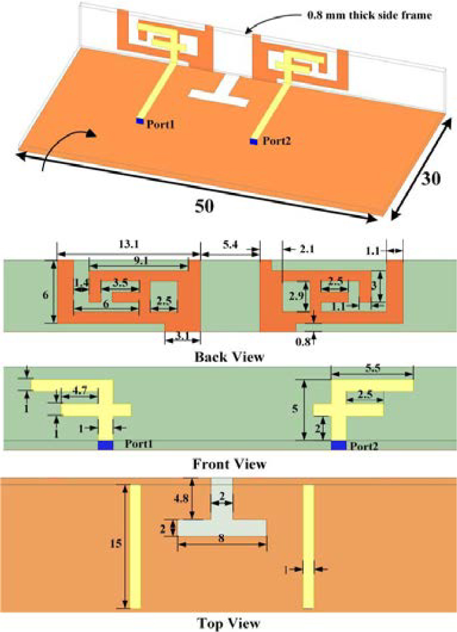
Figure 1: Geometry and dimensions of the proposed antenna pair.
B The theory of characteristic mode analysis
According to CMA [14–17], the characteristic mode fields form a weighted orthogonal set over a conductor surface and the sphere at infinity. The total surface field distribution of an antenna can be obtained by the superposition of each mode field. In CMA, n is a weighting factor defined as modal weighting coefficient (MWC). The MWC reflects the mode contribution of the total field density, and its expression is:
| (1) |
where Vn reflects the coupling of external excitation and characteristic current, which is defined as the mode excitation coefficient (MEC).
Each CM corresponds to a characteristic value n, which represents the ratio of reactive power to radiated power. Modal significance (MS) is closely related to n, which is denoted as:
| (2) |
MSn is independent of the excitation source, and only related to the shape of the conductor. It indicates the potential ability of a CM working in certain bands.
C Design process and analysis
Characteristic mode theory, which was first proposed in 1971 [14], is widely used in antenna design because it can reveal the intrinsic properties of the antenna geometry structure. CMA is used in the design process in our work, with the goal of optimizing the geometrical structure of the antenna pair. The modal significance (MS) is introduced to indicate the potential of each mode in the absence of an external source. Besides, we also observe the surface current of the antenna structure through simulation to guide the design of the antenna structure and adjust the frequency coverage of the antenna. The simulation software are ANSYS HFSS 2020R1 and CST 2020. Due to the symmetry of the structure, only port 1 needs to be simulated and analyzed. In order to clearly show the continuous changes of our design, Figure 2 (a) shows the structural evolution process in four different cases.
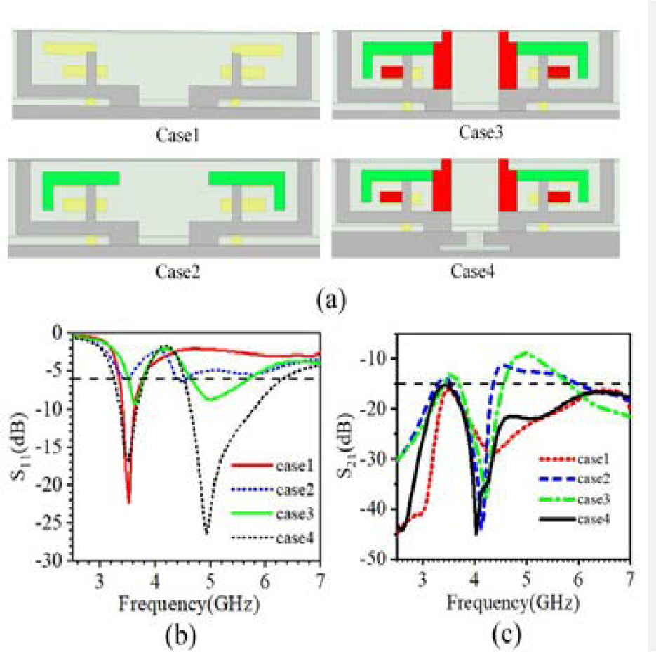
Figure 2: Antenna pair design process. (a) Evolution process of the antenna pair. (b) Comparison of S in four cases. (c) Comparison of S in four cases.
Since the coupled feed antenna includes a feed branch and a short-circuit branch connected to the ground. The gap between the two branches is used to couple energy to the short-circuit branch, which essentially adds capacitive component to the antenna. The short-circuit branch can add inductive component to the antenna. So, the antenna is more possible to produce dual-band resonance and a wider bandwidth. Therefore, we propose a coupled loop element, which is composed of section of feed line, a direct fed F-patch, and a coupled grounded stacked F-patch.
In case 1, two grounded F-shaped patches are placed symmetrically to form an initial antenna pair. The design MS and modal current of case 1 are shown in the Figure 4 (a) and Figure 5 (a). According to the characteristic mode analysis, the current path and current length of 3.5GHz modal current (About 3.5GHz quarter wavelength: 23mm), it can be inferred that the grounded F-shaped patch can effectively excite 3.5GHz resonance. By observing the simulated S11 curve and surface current distribution, it is found that it is highly consistent with the results of characteristic mode analysis, as shown in Figures 2 (b) and 5 (b). It is worth noting that the distance between the two antenna elements in the antenna pair is only 5.4mm (0.065g. g=v/f. Where g is the free space wavelength of 3.5GHz. Where v is the speed of light and f is the value of frequency.), but the isolation is still greater than 15dB, as shown in Figure 2 (c). The main reason is that the two elements of the antenna pair are grounded and symmetrical, their 3.5GHz current paths are symmetrical and in opposite directions, and the energy is radiated in two opposite directions from the gap between the two antenna units and the ground, as shown in Figure 3, so the isolation is very high. Although the resonant frequency and isolation of this antenna pair are very satisfactory, a single frequency band is far from meeting the needs of 5G mobile phones. We also need to modify the antenna pair to generate new resonant modes and cover as many useful frequency bands aspossible.
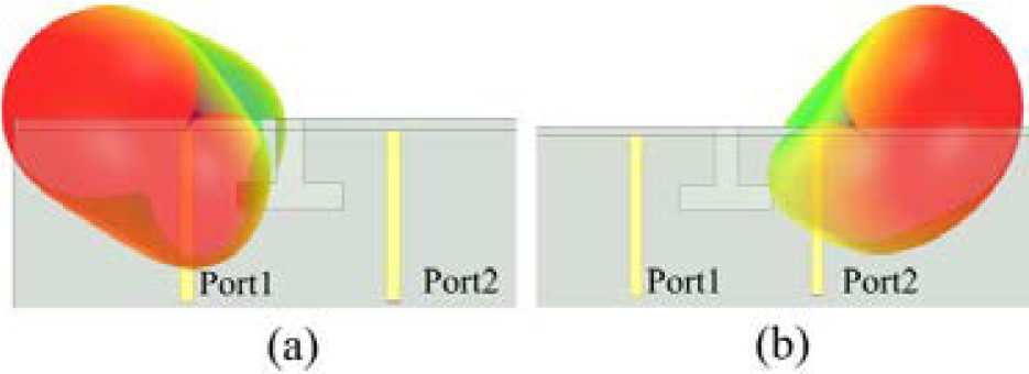
Figure 3: Comparison of radiation directions of port 1 and port 2. (a) Port 1. (b) Port 2.
Next, on the basis of the coupled grounding F-shaped patch, L-shaped branches (Figure 2 (a), green part) are added to form case2 to generate a new mode. Through the analysis of its characteristic mode, it can be seen that two modes of 3.5GHz and 5.5GHz can be excited, as shown in Figure 4 (b). However, from the simulation S11 curve of case 2, as shown in Figure 2 (b), it can be seen that the center frequency, bandwidth and impedance matching of the newly generated high frequency band are not very ideal, so case 2 needs to be modified. Then, on the basis of case 2, the red part in Figure 2 (a) is added to form a stacked F-patch (case3) to adjust the high-frequency resonance point, expand the bandwidth and increase the matching. As shown in Figure 4 (c), the characteristic mode analysis shows that the stacked F-patch has three modes, and three resonances are generated near 3.5GHz, 4.8GHz and 5.5GHz respectively. The three effective modes realize dual frequency resonance and expand the bandwidth of high frequency band. The newly generated modal current of 5.5GHz is shown in Figure 5 (c). From the path of modal current and simulated surface current (Figure 5 (c) and (d)), it can be observed that the antenna is a quarter wavelength resonant mode at 5.5GHz. As shown in Figure 2 (b) and (c), we can roughly observe from the S11 and S21 curves of case2 and case3 that the antenna pair has two working frequency bands and the high-frequency band bandwidth is wide, but the return loss and isolation of the antenna pair are not satisfactory. We also need to improve the structure of the antenna pair to make the return loss of the antenna pair lower and the isolation betterthan 15dB.
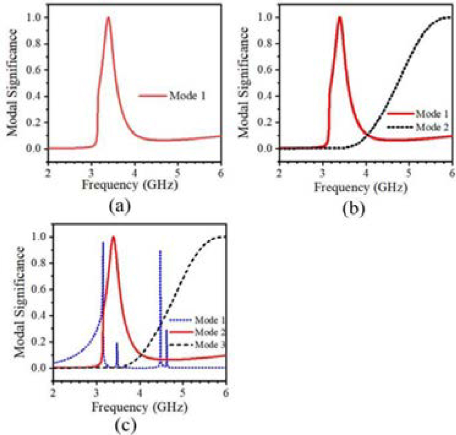
Figure 4: Modal significance. (a) MS of case 1. (b) MS of case 2. (c) MS of case 3.
Finally, the defective ground structure (DGS) is introduced, which is mainly used for impedance matching and reducing the mutual coupling between two units of antenna pair in the high frequency band, so as to further improve its performance. We open a T-shaped slot on the ground of case 3, as shown in Figure 2 (a) case 4. By changing the ground current, the resonant bandwidth can be adjusted and the current coupling between two adjacent ports can be reduced. In Figure 6 (b), we can see that when the antenna is in 5.5 GHz mode, there is a strong ground current (black circle) on the ground. Due to the existence of a strong ground current, there is a strong coupling between the two units of the antenna pair. As can be seen from the comparison between Figure 6 (a) and (b), when we add the DGS structure, the coupling of the ground current is obviously weakened, thus reducing the coupling between the two units. As shown in Figure 2 (b) and (c), after a series of improvements, the impedance matching, isolation and frequency band coverage of the antenna pair corresponding to case 4 have achieved very satisfactory results.
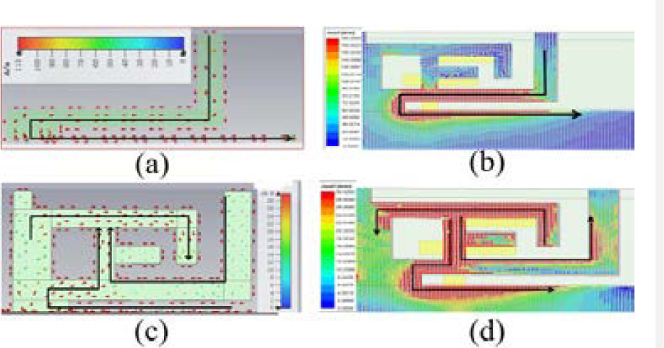
Figure 5: Modal current and simulated surface current distribution at 3.5 and 5.5 GHz. (a) 3.5 GHz modal current in case 1. (b) 3.5 GHz simulated surface current distribution. (c) 5.5 GHz modal current in case 2. (d) 5.5 GHz simulated surface current distribution.
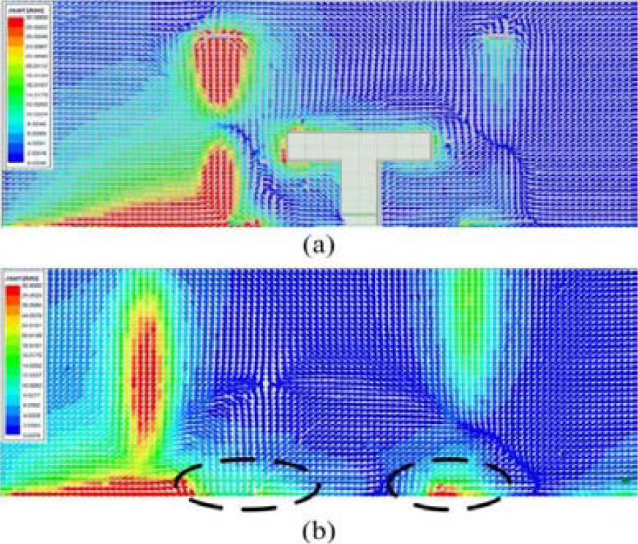
Figure 6: Ground current at 5.5 GHz. (a) With T-shaped slot. (b) Without T-shaped slot.
III. EIGHT-ELEMENT ANTENNA DESIGN AND RESULTS
A Geometry of eight-element antenna array
We use the proposed antenna pair to construct a MIMO antenna array to further improve the capacity of the communication system. As shown in the Figure 7, the overall dimensions of the antenna is 150 75 6.8 mm, which is similar to the size of existing smart phones such as Huawei mate 40 and Xiaomi 11. Four pairs of antenna pairs are placed along the two long frames, and an 8-element antenna array is proposed. Impedance matching and isolation may deteriorate due to changes in the size of the metal ground plane during the composition of the antenna array. We will fine tune the size of the two elements in the proposed antenna pair to reduce the impact of the expansion of the metal ground plane. The distance between antenna pairs on the same side frame is 76.6mm, allowing for future millimeter wave antenna design. To separate the coupling current from one antenna pair to the other and decrease mutual interference between antenna pairs, a 15mm2mm gap is etched on the long side of the ground and a 13mm2mm gap is etched on the short side of the ground. To test the proposed 8-element MIMO antenna array, a prototype is fabricated andmeasured.
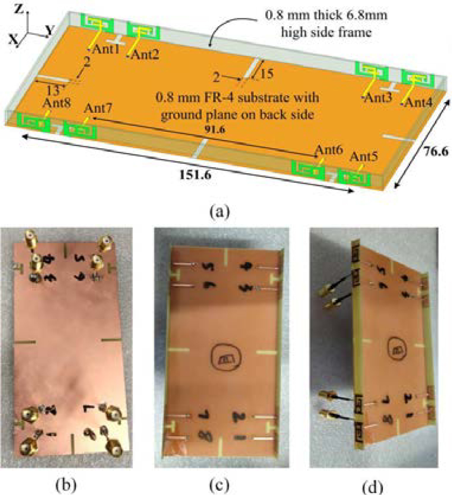
Figure 7: The dimensions and fabrication of the eight-element antenna array (unit: mm). (a) General view. (b) Bottom view. (c) Top view. (d) Side view.
B Performance of antenna array
The reflection coefficient, transmission coefficient, ECC and total efficiency of the eight element MIMO antenna were measured by using vector network analyzer (VNA) instrument keysight E5071C and microwave anechoic chamber. The measured results can fully meet the engineering application. The pictures taken during measurement are shown in Figure 8.
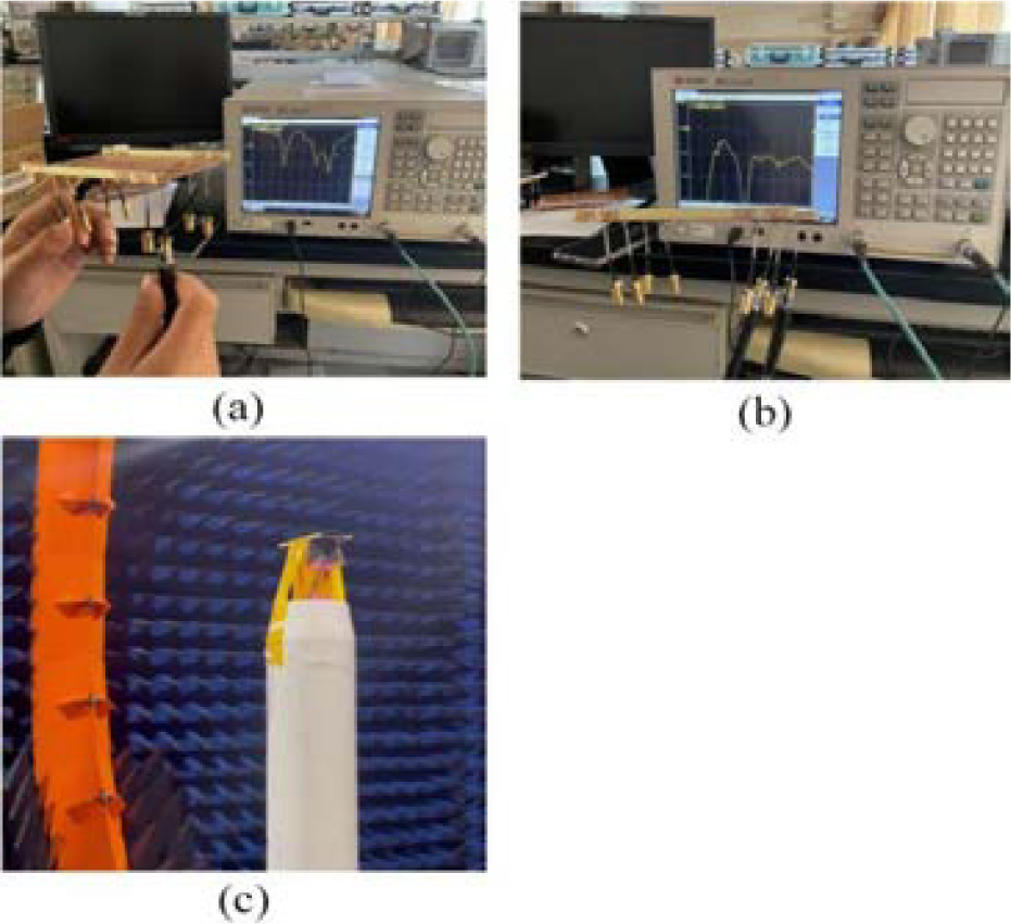
Figure 8: The pictures taken during measurement.
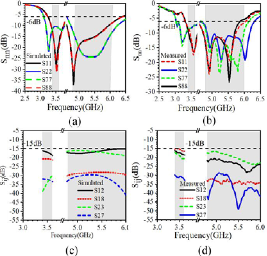
Figure 9: Simulated and measured S-parameters of the proposed antenna. (a) Simulated (b) Measured (c) Simulated (d) Measured
Due to the symmetry of the structure, only half of the elements are selected for discussion. In the Figure 9, the simulated and measured reflection and transmission coefficients are shown respectively. The slight difference between them is due to SMA connector and manufacturing errors. The results show that the working bandwidth of -6dB includes two frequency bands: 3.4GHz-3.6GHz and 4.8GHz-6GHz, which can cover 3.5GHz (3.4GHz-3.6GHz) 5G frequency band, 4.9GHz (4.8GHz-5GHz) 5G frequency band and 5.5GHz (5GHz-6GHz) 5.2GHz WLAN / 5.5GHz WiMAX / 5.8GHz WiFi frequency bands. It can be observed that 15dB isolation is achieved between elements on the same side and on the opposite side.
We measured the total efficiency and ECCs of the antenna through the microwave anechoic chamber. As shown in Figure 10 (a), the measured total efficiency of each element of the antenna is basically better than 50%, and the maximum value can reach 88%. In addition, the envelope correlation coefficients (ECCs) are employed as the metric to evaluate the MIMO performance of the proposed antenna, which are also provided in Figure 10 (b). Obviously, the ECC between any two ports is less than 0.16 (basically 0.1), which reveals the well interference suppressing ability.
The ECC describes the correlation between any two antenna elements in a MIMO antenna array. The lower ECC values lead to higher the diversity gain, which are highly expected in the MIMO antenna array. The ECC between antenna i and j can be calculated using the following formula [18]:
| (3) |
where ECC denotes the ECC between antenna i and antenna j, F(, ) and F(, ) are the field pattern of two radiating elements with respect to and components, * denotes the complex conjugateoperator.
Table 1: Comparison between the proposed and the referenced antennas
| Ref. | Operating band (GHz) | Isolation (dB) | Efficiency (%) | Size (mm) |
| [20] | 3.253.65 | 12 | 5872 | 14 6 |
| [21] | 3.43.6 4.84.9 |
11.8 | Not given | 15 6 |
| [22] | 3.34.2 4.85.0 |
12.5 | 53.879.1 | 18.6 7 |
| [23] | 3.43.6 | 17.5 | 6276 | 25 3 |
| Proposed | 3.43.6 4.86.0 |
15 | 5288 | 13.1 6.8 |
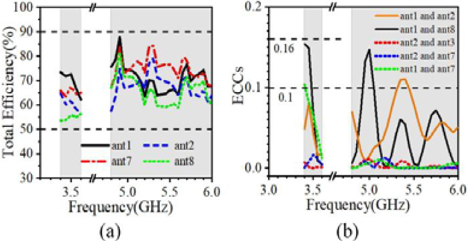
Figure 10: Measured total efficiency and ECCs of the proposed antenna. (a) Measured total efficiency. (b) Measured ECCs.
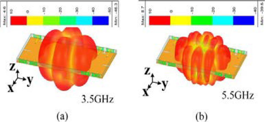
Figure 11: Radiation pattern (Port 1 is excited). (a) 3.5 GHz. (b) 5.5 GHz.
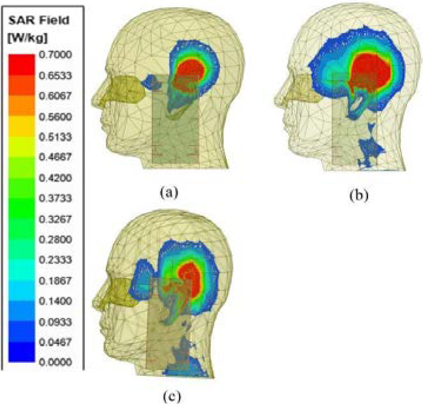
Figure 12: SAR analysis. (a) 3.5 GHz. (b) 4.8 GHz. (c) 5.75 GHz.
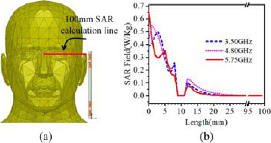
Figure 13: Method of SAR calculation.(a) SAR calculation line. (b) SAR field.
As shown in Figure 11, the radiation pattern of the antenna is analyzed. When the port 1 is excited, the overall radiation of the 8-element MIMO antenna presents omnidirectivity. At 3.5GHz and 5.5GHz, the maximum gain can reach 4.6dB and 8.7dB respectively. It can fully meet the signal quality requirements of 5G mobile phones in the future.
The specific absorption rate (SAR) [18] is the measure of the intensity of backward radiation on per unit mass of the human body. In order to investigate safety concerns of the user, the SAR intensity must be verified. Therefore, the energy absorbed (SAR) by user’s head tissue need not to cross the value of 1.6W/Kg of 1-g tissue, according to American regulator, and 2W/Kg of 10-g tissue, according to European regulator. Full wave electromagnetic simulator can be used to extract SAR values directly. The full wave electromagnetic simulator ANSYS HFSS 2020R1 is used to estimate the SAR of the model. The antenna is placed near the head of a realistic human model. In the simulation, the antenna is placed 2mm away from the human head [19]. The input power of each unit of the antenna is 25mW, so the total input power is 200mW. Figure 12 shows the SAR results of the antenna for 1-g tissue. The SAR peak values at 3.5GHz, 4.8GHz, and 5.75GHz are 0.54W/Kg, 0.49W/Kg, and 0.65W/Kg respectively, as shown in the Figure 13. It can be seen that the antenna is safe for operation in vicinity of the human body.
Table 1 shows the comparison between the proposed antenna and other recently reported smartphone 5G MIMO antennas. It can be seen that most eight-element antennas can only cover a single frequency band, and a few antennas that can cover dual frequency bands have the problems of small number of antenna units and low isolation. However, our proposed antenna can not only cover multiple useful frequency bands, but also achieve high isolation ( 15dB).
IV. CONCLUSION
In this work, we propose a compact dual-band dual-antenna pair and form an eight elements MIMO system, which resonates in the frequency bands of 3.4GHz-3.6GHz and 4.8GHz-6GHz, and realizes the impedance bandwidth of 200MHz and 1200MHz respectively based on vswr3:1 criteria. Also, the isolation between the ports is below -15dB and ECC is basically less than 0.1 for the whole band of interest. Moreover, the SAR study is conducted to understand the interaction of the system with the human body and it is found that it is safe to use within the vicinity of human body. The proposed antenna pairs were placed at the sides of the chassis with two antenna pairs on each side. Sufficient space is reserved for future millimeter wave antenna design and various sensor installation. The proposed antenna system can be termed as potential candidate for future 5G smart phone terminals.
ACKNOWLEDGMENT
The authors extend appreciation to the support of the National Natural Science Foundation of China (Grant No. 51965047), the Natural Science Foundation of Inner Mongolia (Grant No. 2021MS06012) and the Key Scientific and Technological Project of Inner Mongolia (Grant No. 2020GG0185) for this project.
REFERENCES
[1] H. Zhu, X. Guan, B. Ren, and C. Wang, “Dual-band eight-element MIMO antenna consisted of tightly arranged hybrid antenna pairs for 5G smartphone,” Int. J. RF Microwave Comput.-Aided Eng., vol. 31, no. 12, Art. no. e22886, 2021.
[2] W. Wang, Y. Wu, W. Wang, and Y. Yang, “Isolation enhancement in dual-band monopole antenna for 5G applications,” IEEE Trans. Circuits Syst. II: Express Briefs, vol. 68, no. 6, pp. 1867-1871, 2021.
[3] A. S. Elkorany, A. N. Mousa, S. Ahmad, D. A. Saleeb, A. Ghaffar, M. Soruri, M. Dalarsson, M. Alibakhshikenari, and E. Limiti, “Implementation of a miniaturized planar tri-band microstrip patch antenna for wireless sensors in mobile applications,” Sensors, vol. 22, no. 2, 2022.
[4] P. Mathur, R. Augustine, M. Gopikrishna, and S. Raman, “Dual MIMO antenna system for 5G mobile phones, 5.2 GHz WLAN, 5.5 GHz WiMAX and 5.8/6 GHz WiFi applications,” IEEE Access, vol. 9, pp. 106734-106742, 2021.
[5] H. D. Chen, Y. C. Tsai, C. Y. D. Sim, and C. Kuo, “Broadband eight-antenna array design for sub-6 GHz 5G NR bands metal-frame smartphone applications,” IEEE Antennas Wireless Propag. Lett., vol. 19, no. 7, pp. 1078-1082, 2020.
[6] X. T. Yuan, Z. Chen, T. Gu, and T. Yuan, “A wideband PIFA-pair-based MIMO antenna for 5G smartphones,” IEEE Antennas Wireless Propag. Lett., vol. 20, no. 3, pp. 371-375, 2021.
[7] M. Shafi, A. F. Molisch, P. J. Smith, T. Haustein, P. Zhu, P. De Silva, F. Tufvesson, A. Benjebbour, and G. Wunder, “5G: A tutorial overview of standards, trials, challenges, deployment, and practice,” IEEE J. Selected Areas Commun., vol. 35, no. 6, pp. 1201-1221, 2017.
[8] H. Zou, Y. Li, B. Xu, Y. Chen, H. Jin, G. Yang, and Y. Luo, “Dual-functional MIMO antenna array with high isolation for 5G/WLAN applications in smartphones,” IEEE Access, vol. 7, pp. 167470-167480, 2019.
[9] D. Serghiou, M. Khalily, V. Singh, A. Araghi, and R. Tafazolli, “Sub-6 GHz dual-band 8 8 MIMO antenna for 5G smartphones,” IEEE Antennas Wireless Propag. Lett., vol. 19, no. 9, pp. 1546-1550, 2020.
[10] L. Sun, H. Feng, Y. Li, and Z. Zhang, “Compact 5G MIMO mobile phone antennas with tightly arranged orthogonal-mode pairs,” IEEE Trans. Antennas Propag., vol. 66, no. 11, pp. 6364-6369, 2018.
[11] W. Jiang, B. Liu, Y. Cui, and W. Hu, “High-isolation eight-element MIMO array for 5G smartphone applications,” IEEE Access, vol. 7, pp. 34104-34112, 2019.
[12] X. T. Yuan, W. He, K. D. Hong, C. Z. Han, Z. Chen, and T. Yuan, “Ultra-wideband MIMO antenna system with high element-isolation for 5G smartphone application,” IEEE Access, vol. 8, pp. 56281-56289, 2020.
[13] H. F. Abutarboush, W. Li, and A. Shamim, “Flexible-screen-printed antenna with enhanced bandwidth by employing defected ground structure,” IEEE Antennas Wireless Propag. Lett., vol. 19, no. 10, pp. 1803-1807, 2020.
[14] D. Gao, Z. X. Cao, S. D. Fu, X. Quan, and P. Chen, “A novel slot-array defected ground structure for decoupling microstrip antenna array,” IEEE Trans. Antennas Propag., vol. 68, no. 10, pp. 622-628, 1971.
[15] R. Harrington and J. Mautz, “Theory of characteristic modes for conducting bodies,” IEEE Trans. Antennas Propag., vol. 19, no. 5, pp. 7027-7038, 2020.
[16] J. Dong, S. Wang, and J. Mo, “Design of a twelve-port MIMO antenna system for multi-mode 4G/5G smartphone applications based on characteristic mode analysis,” IEEE Access, vol. 8, pp. 90751-90759, 2020.
[17] Y. Q. Hei, J. G. He, and W. T. Li, “Wideband decoupled 8-element MIMO antenna for 5G mobile terminal applications,” IEEE Antennas Wireless Propag. Lett., vol. 20, no. 8, pp. 1448-1452, 2021.
[18] H. Arai, Measurement of Mobile Antenna Systems. London, U.K.: Artech House, 2001.
[19] IEEE Recommended Practice for Determining the Peak Spatial-Average Specific Absorption Rate (SAR) in the Human Head from Wireless Communications Devices: Measurement Techniques, IEEE Standard-1528, Dec. 2003.
[20] S. H. Kiani, A. Altaf, M. Abdullah, F. Muhammad, N. Shoaib, M. R. Anjum, R. Damaševičius, and T. Blažauskas, “Eight element side edged framed MIMO antenna array for future 5G smart phones,” Micromachines, vol. 11, no. 11, 2020.
[21] L. Chang, G. Zhang, and H. Wang, “Dual-band antenna pair with lumped filters for 5G MIMO terminals,” IEEE Trans. Antennas Propag., vol. 69, no. 9, pp. 5413-5423, 2021.
[22] L. Cui, J. L. Guo, Y. Liu, and C. Y. D. Sim, “An 8-element dual-band MIMO antenna with decoupling stub for 5G smartphone applications,” IEEE Antennas Wireless Propag. Lett., vol. 18, no. 10, pp. 2095-2099, 2019.
[23] Y. Li, C. Y. D. Sim, Y. Luo, and G. Yang, “High-isolation 3.5 GHz eight-antenna MIMO array using balanced open-slot antenna element for 5G smartphones,” IEEE Trans. Antennas Propag., vol. 67, no. 6, pp. 3820-3830, 2019.
BIOGRAPHIES

Yonghao Wang received his bachelor’s degree in communication engineering from Shandong University of Science and Technology in Qingdao, China in July 2020. From September 2020, he studies for a master’s degree in electronic and communication engineering at Inner Mongolia University, Hohhot. China. His research interests are to research and design 5G miniaturized high isolation dual band MIMO antenna for mobile phone.

Xin Wang received a doctor’s degree in engineering in Instrument Science and technology of Zhong-bei University, she is currently working in the College of Electronic Information engineering, Inner Mongolia University, Hohhot. China. Her research interests are micro nano RF devices (antennas, filters, couplers, etc.), metamaterial antenna.

Junlin Wang received a doctor’s degree in engineering in Instrument Science and technology of Zhong-bei University. He is currently working in the College of electronic information engineering, Inner Mongolia University, Hohhot. China. His research interests are micro nano RF devices (antennas, filters, couplers, etc.), metamaterial antenna.

Rui Shao received a bachelor’s degree in communication engineering from Shandong University of Technology, Zibo, China, in July 2020. From September 2020, she studies for the master’s degree of Information and Communication Engineering at Inner Mongolia University, Hohhot, China. Her research interests are to research and design 5G high isolation MIMO antenna.
ACES JOURNAL, Vol. 37, No. 5, 588–596.
doi: 10.13052/2022.ACES.J.370508
© 2021 River Publishers